In-Situ XPS Monitoring and Characterization of Electrochemically
Prepared Au Nanoparticles in an Ionic Liquid
Merve T. Camci,
†Burak Ulgut,
†Coskun Kocabas,
‡and Sefik Suzer
*
,††Department of Chemistry and‡Department of Physics, Bilkent University, 06800 Ankara, Turkey
*
S Supporting InformationABSTRACT: Gold nanoparticles (Au NPs) have been electrochemically prepared in situ and in vacuo using two different electrochemical device configurations, containing an ionic liquid (IL), N-N-diethyl-N-methyl-N-(2-methoxyethyl)-ammonium bis(trifluoromethanesulfonyl)imide, that serves both as reaction and as stabilizing media for the NPs. It was observed in both devices that Au NPs were created using an anodically triggered route. The created Au NPs are relatively small (3−7 nm) and reside within the IL medium. X-ray photoelectron spectroscopy is utilized to follow not only the formation of the NPs but also their charging/discharging properties, by monitoring the charging shifts of the Au4f peak representing the electrodes and also the Au NPs as well as the
F1s peak of the IL after polarizing one of the electrodes. Accordingly, DC polarization across the electrodes leads to a uniform binding energy shift of F1s of the IL along with that of Au4f of the NPs within. Moreover, this shift corresponds to only half of the applied potential. AC polarization brings out another dimension for demonstrating further the harmony between the charging/discharging property of the IL medium and the Au NPs in temporally and laterally resolved fashions. Polarization of the electrodes result in perfect spectral separation of the Au4f peaks of the NPs from those of the metal in both static (DC) and in time- and position-dependent (AC) modes.
1. INTRODUCTION
It is difficult, if not impossible, to incorporate conventional electrochemical setups into high/ultrahigh vacuum chemical analysis techniques such as X-ray photoelectron spectroscopy (XPS), owing to the volatility or chemical instability of aqueous and organic electrolytes. Ionic liquids (ILs) at room temper-ature overcome both of these shortcomings because they have very low vapor pressures (∼10−12mbar)1and are stable against X-rays, where significant beam damage and/or visible physical change(s) are not observable under X-ray illumination within laboratory-based instruments.2Moreover, ILs exhibit sufficient electrical conductivity (∼10−2cm−1),3avoiding spectral artifacts such as peak shape distortion and/or nonstoichiometry.4−7 Because XPS provides chemically resolved information, changes in the electronic structure of the constituents, such as the chemical states and/or their environment as a result of chemical/electrochemical reactions/processes, can easily be revealed. For example, the binding energy of the Au4f7/2peak is 84.0 eV, corresponding to the neutral gold atoms within the metal or small-sized particles, which are considered to be formally at zero oxidation state (Au0). However, it is shifted by 1.1 and 3.2 eV to higher binding energies when gold is at +1 (Au1+) and +3 (Au3+) oxidation states, respectively, all of which are easily resolved.8−11
Nanosized metal particles are utilized for a wide range of applications in science and technology because of their unique
properties that differ from those of their bulk.12Syntheses of highly dispersed and narrow-sized metal nanoparticles (NPs) within aqueous and/or organic solvents usually require the usage of additional surfactants, capping agents, and/or stabilizers during the preparation processes.13 Among the other favorable properties, ILs also appear to offer a suitable medium for metal NP syntheses in terms of dispersity and stability of the particles.14,15 Numerous researchers have provided evidence about the important role(s) of ILs in the preparation of metal NPs, as they have a high charge density and self-organized structures in molecular scales.16−21 The current understanding of ILs facilitating spontaneous NP synthesis relies on two factors: (i) ILs provide directional and continuous ionic channels and (ii) ILs are entropic drivers. This subject and the other stabilization properties of ILs have been reviewed by Dupont and Scholten.22,23Similarly, Scheeren and co-workers reported the effective interaction between ILs and an organometallic platinum surface that leads to a simple decomposition of the Pt precursor into much smaller (around 2.3 nm) Pt NPs, and based on the XPS analyses, they claimed that Pt NPs were stabilized through the formation of chemical bonds with the IL.24,25
Received: December 2, 2016 Accepted: January 27, 2017 Published: February 10, 2017
Article
http://pubs.acs.org/journal/acsodf
NP syntheses as they combine the electrostatic stabilization because they are composed of merely ions and steric stabilization through the restriction of the free motion of the NPs by the ionic fragments.32 In addition to the simple decomposition of organometallic precursors, NPs can also be obtained by energetic bombardment of the bulk metal precursors, resulting in nanosized particles within ILs. Laser-induced fragmentation of transition metal NPs in ILs was reported for the control of shape and size.33 A single-step synthesis of Au−Ag alloy NPs was reported using a cosputter deposition technique, where it was also advocated that this route was superior to the conventional solution-based ones, which are dictated by the redox potential, hence not easy to control.34 Another study reported on the bombardment of metal precursors by energetic Ar+ions, resulting in the physical ejection of small clusters from the bulk generating small clusters, where the created nanosized Au particles were found to be arranged as clusters on the surface of the particular IL.35 Another important use of ILs is as electrolytes for electrochemical deposition of mono- and/or bimetallic metal NPs where the electrochemical reactions are driven by the applied potentials.36,37 Here, in addition to the ex situ characterization of the reaction products, XPS offers an unequivocal opportunity for monitoring in situ liquid phase reactions through the binding energy shifts as a result of chemical state changes. The in situ reduction of the Pd2+ions to Pd0species in an IL was monitored by following the changes in the Pd3d photoelectron signal intensities corresponding to a decrease in the intensity of Pd2+with an accompanying increase in the Pd0peaks, where the binding energy positions of the two oxidations states were clearly resolved.1 In a different study, Taylor et al. reported on monitoring the electrochemical reduction of Fe3+ species to Fe2+ in a two-electrode electrochemical cell using an externally connected potentiostat in real time, by following the changes in the oxidation states of the corresponding photoelectron peaks together with cyclic voltammograms recorded inside of the vacuum chamber.38 In their following work, dissolution of copper metal and the electrochemical formation of cationic Cu+ species were identified by XPS in a time-dependent fashion, again by following the intensity changes of the peaks in the Cu2p region.39Similarly, Compton and co-workers had studied the real-time electrodeposition of potassium metal in an electro-chemical cell containing potassium salt dissolved in an IL connected to the potentiostat, while recording the K2s peak with respect to time.40 Later on, they reported the electro-deposition of another group 1A metal, rubidium, that cannot be electrodeposited from aqueous or organic solvents because of their narrower electrochemical potential windows, while monitoring not only the increase in the intensity of Rb3d
N-diethyl-N-methyl-N-(2-methoxyethyl)ammonium bis-(trifluoromethanesulfonyl)imide (DEME-TFSI).46 In that work, we have also stated that a prolonged application of +3 V bias leads to the formation of Au NPs in the vicinity of the polarized electrode (i.e., oxidation-mediated electrocorrosion) but within the IL medium and also mentioned that the details would be the subject of future work. The present work is the follow-up of that statement, where we will now raise and try to answer three important questions: (i) Is the reaction predominantly electrochemically driven; if so, anodically or cathodically triggered? (ii) Are the Au NPs neutral or charged? (iii) And where do the NPs reside: within the IL medium or deposited on the metal electrodes? The two Au electrodes used in a coplanar capacitor geometry also seem to offer a convenient platform for elucidating the mechanism(s) of this electrocorrosion process, because of the symmetric nature of the electrodes in terms of their chemical nature and size. In trying to answer these questions, we will frequently bring up ourfindings from our previous work, where the electrode and/ or the IL medium charging, upon imposing external potential bias, was monitored in a static and a dynamic fashion via the experimentally determined potential-dependent XPS binding energy shifts of the corresponding core levels, mainly the F1s (at 688.5 eV) and Au4f7/2(at 84.0 eV) peaks representing the IL and the gold electrodes, respectively. An additional simple galvanic electrochemical preparation route was also introduced to facilitate the Au NP production, also ensuring the removal of them from the device and use for additional optical and microscopic characterization.
2. RESULTS
In the first stage, we have used the same experimental arrangement as in our previous work, where two Au electrodes were fabricated, in the source−drain geometry, on a porous polyethylene membrane (PEM) containing the impregnated IL as the medium, providing electrical conductivity. The experimental details are reproduced in Figure S1 together with the chemical composition confirmation of the atomic constituents of the IL medium (Figures S2 and S3). However, this time we have carried out XPS measurements in much longer time scales of up to several days. Additionally, in parallel investigations, we have checked the stability of both the IL and the fabricated gold electrodes in vacuum and under X-ray exposure in the above-mentioned time scales but without imposing any potential across the electrodes. As a result, we can confidently say that no significant corrosion was observed. Hence, at the outset, we can state that the Au NP formation is triggered electrochemically within our experimental arrange-ment. However, we should also mention that occasionally, we have observed the formation of wine-colored features near the metal electrodes, which we attribute to the Au NPs after a very
long (>3 days) exposure of the device to air, triggered most probably by ambient photochemical means.
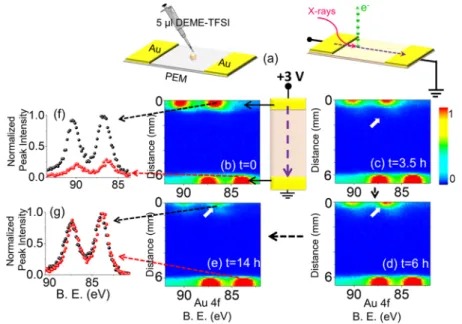
2.1. Monitoring Electrocorrosion. We imposed a +3 V DC stress while recording consecutive XP spectra in the line scan mode as snapshots of the Au4f region, with 100μm X-ray spot- and 100μm step-sizes between each data point, starting from the source electrode to the drain, as shown inFigure 1. The imposed voltage caused a current flow between the electrodes, which was high at the beginning but reached a steady-state value of∼14 nA as measured by the source meter (see also Figure S4 for variation in the current with time), which also caused corrosion at the anodically polarized Au electrode. This device geometry is also suitable for real-time reaction monitoring at the electrodes. The corrosion was noticeable by the physical changes in the electrode accom-panied by the formation of secondary Au species at the
electrode/IL interfacial region only in the polarized electrode, by examining the Au4f spectra recorded in the line scan mode across the entire device repetitively as the device was subjected to external biasing up to 14 h continuously. Figure 1 also depicts four line spectra of the Au4f region under the +3 V bias, where the x-axes correspond to the binding energy in eV and the y-axes correspond to the distance in millimeters from the polarized electrode toward the grounded one, recorded at the beginning, after 3.5, 6, and 14 h. The color bar indicates the variations in the normalized intensity of the corresponding Au4f or F1s peaks.
The Au4f spin−orbit doublet appeared at 84.0 and 87.7 eV at the grounded electrode but shifted to 87.0 and 90.7 eV at the polarized one. The intense Au4f peak at the source electrode at the beginning of the experiment decreased throughout the measurement, as shown inFigure 1f, whereas it was virtually Figure 1.(a) Schematics of the device. XP spectra of the Au4f region, recorded in the line scan mode from the source toward the drain electrodes; (b) at the beginning of the experiment (t = 0), (c) after 3.5 h (t = 3.5 h), (d) 6 h (t = 6 h) and (e) 14 h (t = 14 h) during the continuous application of +3 V DC external potential. The color bar represents the peak intensities. The schematic illustration represents the line scan direction and the source−drain geometry including the electrical connections. The normalized Au4f spectra from the two points on the line at different positions are given (f) at 500μm and (g) at 6000 μm away from the polarized electrode.
Figure 2.XP spectrum of the Au4f region, recorded in the line scan mode from the source toward the drain electrodes; (a) at the beginning of the experiment (t = 0), after (b) 3.5 h (t = 3.5 h), (c) 6 h (t = 6 h), and (d) 15 h (t = 15 h) during the continuous application of−3 V DC external potential. (e) Normalized Au4f spectra at 6000μm away from the polarized electrode at the beginning (black graph) and end (red graph) of the experiment.
the same at the drain side, all throughout (Figure 1g). In parallel, a second type of Au species started ascending from the source side with low intensity, which will be discussed in more detail later. However, neither a different ionic species nor a measurable electrode corrosion was detected by XPS at the grounded electrode. The corrosion at the source side under a +3 V DC potential was emphasized by comparing the intensity of the Au4f peaks recorded at a particular position d = 0.5 mm corresponding to thefifth point on the entire line scan starting from the polarized electrode, at the beginning of the measurement and after 14 h. The spectra that were also normalized in intensity and shown inFigure 1f confirmed the corrosion of the polarized electrode by the significant decrease (∼70%) in the intensity of Au4f photoelectron peaks after 14 h by applying the +3 V DC. In contrast, the normalized spectra, recorded at the position d = 6.0 mm near the drain side of the device (Figure 1g), displayed almost no change as an indication of the absence of electrode corrosion and/or secondary species formation.
The potential was switched from +3 to −3 V DC after a certain number of line scans were recorded to probe“whether there is also an electrochemical reaction taking place at the grounded electrode upon reversal of the polarization”. Measurements were taken using exactly the same experimental conditions except for the reversal of the polarization for 15 h continuously, as depicted in Figure 2. Under the −3 V polarization, the Au4f spin−orbit doublet appeared still at 84.0 and 87.7 eV at the grounded electrode but then was shifted to 81.0 and 90.7 eV at the negatively polarized electrode. The spectra shown inFigure 2a−d for both the source and the drain sides display no apparent change in intensity. As highlighted in Figure 2e, the normalized Au4f spectra, recorded again at the beginning of the−3 V DC potential application and also after 15 h at the position d = 6.0 mm, confirmed that there was neither electrocorrosion nor secondary Au species formation at the drain-side of the device. Therefore, we can now state that the electrocorrosion is definitely anodically triggered.
To elaborate on the new Au species formed, we zoomed in on the interface and recorded data using an X-ray spot size of
50μm and recorded line scan Au4f spectra with 50 μm step sizes for about 1 mm while imposing +3, 0, and−3 V DC bias, as depicted in Figure 3a. Although the secondary Au species appear as a tail of the electrode, and their spectral positions cannot be separated from those of the metallic Au4f ones when the device is grounded, they get completely separated under both positive and negative biases. In Figure 3c, two Au4f spectra that represent two different points on the line scan are shown. The red spectra correspond to the metallic Au4f of the Au electrode at the 2nd position on the line, and the green spectra correspond to the new Au species at the 11th position on the line. Note also that the intensities of the Au4f peaks of the new Au species, as shown both in Figure 3a,c, are significantly smaller. The spectral separation is related to the charging property of the surrounding medium of the new Au species, which, in actuality, is the IL medium itself. Therefore, it is best to relate the peak positions to the F1s peak of the IL, which are also shown inFigure 3b.
As pointed out in our previous paper, as a result of the symmetric voltage drop at the two Au−IL interfaces, the entire IL medium retained only half of the applied potential, which was also uniform within the IL medium. Hence, throughout the entire IL medium surface, the F1s experienced approximately only +1.5 and−1.5 eV shifts from the grounded position when +3.0 and −3.0 V bias were applied. The measured binding energies are given inTable 1, and a schematic diagram of the Figure 3.(a) Au4f and (b) F1s XP spectra in line scan mode along 1 mm from the source-electrode point recorded under the application of +3, 0 (grounded), and−3 V DC potentials. (c) Au4f XP spectra recorded in a higher resolution (normal scan mode) at two different positions indicated.
Table 1. Measured Binding Energies B.E. (eV), +3 V bias B.E. (eV), ground B.E. (eV),−3 V bias 2nd position Au4f7/2(metal) 87.1 84.1 81.2 F1s 691.0 689.3 687.6 difference 603.9 605.1 606.4 11th position Au4f7/2(2nd Au sp.) 86.5 84.7 83.2 F1s 691.0 689.2 687.6 difference 604.5 604.5 604.4
potential drop across the electrodes is given in theFigure S5. As can be gathered fromFigure 3a andTable 1, this is more or less the shift exhibited by the new Au species, and its uncharged binding energy can now be estimated using the binding energy differences between the F1s and the Au4f7/2peaks and working backwards to yield a value of (688.5− 604.5) = 84.0 ± 0.1 eV, exactly the same value of the neutral Au0, hinting that the new Au species are neutral Au particles. This point will be corroborated with additional experimental data in the following sections.
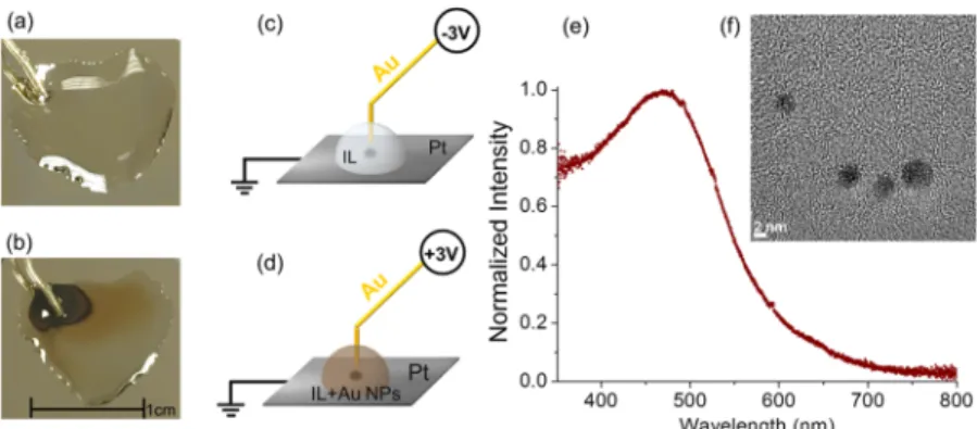
2.2. Role of the Electrode Nature. To further investigate the role of the nature of the electrode in NP formation, a different geometry was adopted, where the ground electrode was now replaced by a Pt electrode and a Au wire was used as the sacrificial electrode, dipped into the IL drop, as shown in Figure 4. Application of−3 V continuously for ∼60 h in the vacuum chamber of the spectrometer resulted in no visible change within the IL, as shown inFigure 4a and schematically described inFigure 4c. In stark contrast, application of +3 V for the same duration resulted in the formation of the well-known wine-colored Au NPs, a picture of which is given inFigure 4b and schematized in Figure 4d. The visible spectrum of the resultant IL solution is shown inFigure 4e. The strong surface plasmon resonance peak of the Au NPs centered at 470 nm is consistent with the previously reported data on Au NPs in ILs.47 A transmission electron microscopy (TEM) image, shown inFigure 4f, verified the formation of Au NPs, having a nearly spherical shape and with a particle size ranging between 3 and 7 nm. At higher magnifications, the lattice fringes of the Au NPs were clearly observable, as shown in Figure S7, revealing the crystalline nature of Au NPs. At this point, we can reiterate that anodically triggered electrocorrosion produces oxidized Au species, most probably Au1+, which transfer into the IL medium, get reduced, and eventually coalesce to form Au NPs.
It is also possible to estimate the order of the magnitude of the concentration of the electrochemically prepared Au NPs in this geometry using the measured steady-state current reached under +3 V potential, which was 30 nA on average for the duration of 60 h ([30× 10−9C/s× 60 h × 3600 s/h]/[96 485 C/mol e−] = 70× 10−9mol e−) and assuming that the oxidized Au species have +1 charge (i.e., Au1+), to yield∼70 nmol Au1+, which somehow get reduced within the IL and are converted to neutral Au atoms which eventually coalesce to Au0NPs. Hence, the concentration of Au0atoms within the∼10 μL IL medium can be approximated as ∼0.001 M (moles/L). This
concentration can also be related to the measured absorbance value of∼1.0 in the visible spectrum of the Au NPs, as shown inFigure 4e, using
= ∈ × × A(Absorbance) b c
where ∈ is the extinction coefficient, reported to be on the order of 3−6 × 10⁶/M·cm;48
b is the thickness of the ILfilm prepared for recording the visible spectrum, estimated to be ∼10 μm; and c is the concentration (∼1 mM) of the solution. These numbers yield an estimated absorbance of 1, consistent with the measured value.
2.3. Static Response of the Au NPs and the IL Medium. To get detailed XPS data on the electrochemically prepared Au NPs in DEME-TFSI using this geometry, we transferred 5μL of the IL containing the electroformed Au NPs onto the PEM of the previously described device with two coplanar Au electrodes, as schematically described inFigure 5.
The liquid wets the surface of the device and impregnates the membrane. The device was then analyzed using XPS in the familiar source−drain geometry. Detailed survey spectra recorded throughout the entire device indicate (i) no sign of Pt4f peaks, (ii) stoichiometric IL, and (iii) presence of ample Au4f peaks everywhere.
Here again, the strategy of polarizing the electrodes is employed to characterize and separate the Au NP peaks from those of the electrodes. Therefore, XPS line scan data were collected using an X-ray spot size of 50μm and a step size of 50 μm in the scanning mode for both Au4f and F1s regions, similar to the ones displayed in Figure 3. The line scans are shown inFigure 6a,b for the Au4f and F1s regions, respectively, Figure 4.Images of the device and the IL medium after prolonged application of (a)−3 and (b) +3 V, for 60 h to the Au wire. The processes are schematized in (c) and (d). (e) Visible spectrum and (f) TEM image of Au NPs in the IL created by +3 V polarization of the Au wire. Only the anodically polarized Au wire leads to the formation of wine-colored NPs.
Figure 5. Schematic representation of the device preparation in source−drain geometry using the Au NPs generated between Au and Pt electrodes in DEME-TFSI.
and represent a collection of spectra that were scanned along the indicated 2 mm line, starting from the electrified electrode toward the middle of the IL device, and the color bar represents the intensities of the photoelectron peaks. As already shown in Figure 3, the Au4f spectra cannot be separated/differentiated when grounded but can be completely separated upon application of +3 and −3 V biases, whereas no separation in terms of secondary species formation or splitting of the peaks were observable for the F1s region, only displaying a uniform
∼1.5 eV shift, which is again only half of the applied potential to the electrode. Therefore, we assigned one of the Au4f spin− orbit doublets to the polarized gold electrode and the other to the wine-colored Au0NPs within the IL medium of the device. The harmony between Au0 and the IL medium is attained because the binding energy shifts of the corresponding Au4f and F1s peaks are similar to the applied potential (i.e., only half of it), displaying a different behavior when compared with the static (DC) response of the Au electrode.
Figure 6.XP spectra of (a) Au4f and (b) F1s regions, recorded in the line scan mode from the source electrode toward the middle of the device under +3, 0 (grounded), and−3 V DC bias.
Figure 7.Time-resolved (1 s) XP spectra of the Au4f and F1s regions under 10 mHz 3 V SQW excitation recorded at four different lateral positions. Each graph displays a total of 200 spectra, recorded in 200 s.
2.4. Dynamic Response of the Au NPs and the IL Medium. In our previous work, we also demonstrated that the time-dependent charging behavior of the F1s photoelectron peak of the DEME-TFSI IL was found to be different at different lateral positions, which is also reproduced in Figure S8.46Therefore, one can speculate that the Au NPs dispersed in IL should also have a similar behavior. To test this hypothesis, we recorded time-dependent XP spectra with 1 s time resolution, while imposing slowly varying 10 mHz square-wave pulses (SQW) with 3 V amplitude at four different lateral positions along the device, as depicted inFigure 7.
Thefirst and fourth points indicated by the red line are on the biased and grounded electrodes, respectively, whereas the second and third points are near the IL/electrode interfaces. DEME-TFSI drop spreads over the entire device including the Au electrodes; hence, the F1s peak is detectable on both Au electrodes and in the IL medium containing the NPs. Under the external 10 mHz SQW pulses, the Au4f peaks of the metal do not show any time-dependent changes in both electrodes, except for the uniform +3.0 eV shift to the higher binding energy from the grounded position during the positive cycle and−3.0 eV shift in the negative one for the source side and absolutely no shift in the drain side because it is always grounded. By contrast, the position of the F1s peak exhibits strong time dependency at all four points, which are laterally varying also. As discussed in our previous work, their polarization directions are completely opposite to each other on the polarized and the grounded electrodes. Of paramount interest is the fact that the Au4f spectra of the Au NPs are also harmonized with the F1s of the IL medium, which also proves our hypothesis.
3. DISCUSSION
There have been reports of electrochemical gold etching in aqueous medium and under applied potential. Most of these reports detail applied potential waveforms on gold electrodes in acidic solutions.45,47−49 These waveforms involve potentials that are anodic enough to form a layer of gold oxide and potentials that are cathodic enough to reduce this layer. The stresses created on the gold electrode that form upon the creation and breakdown of the gold oxidefilm lead to NPs of gold to detach from the electrode. In some reports involving electrochemical gold etching, the etching is done under applied anodic potentials.50 When the etching is only anodic, it is generally assumed that the dissolution goes through a simple oxidation of metallic gold into cations (Au+ or Au3+) that are then complexed with the Cl− or CN− ions in the solution. However, because the thrust of these studies was not the details of the etching process, further analyses were not reported. Our findings suggest that in our system of gold electrode in DEME-TFSI, the electrochemically oxidized gold species on the surface of the electrode creates enough strain on the gold surface that leads to dislodging from the electrode surface. These species eventually get reduced and lead to Au NP formation, stabilized in the IL medium, which is consistent with the numerous experimental and theoretical studies reported.51,52 Further experimental and theoretical work is needed to elucidate the mechanism(s) and the role(s) of each and every species and/or medium involved.
4. EXPERIMENTAL SECTION
PEM (20 μm thickness) (Celgard 2730, Gelon LIB Group) with a porosity of 43% was used for the device fabrication. Electrochemistry-grade IL (≥98.5%) DEME-TFSI was pur-chased from Sigma-Aldrich (CAS number: 464927-84-2). In the first electrochemical device, the two Au electrodes were sputtered from a Au target onto the two sides of the 20 μm-thick porous PEM in a low vacuum environment around 0.15 mbar and 25 mA discharge current for 80 s using a conventional plasma sputter-coating. DEME-TFSI or the DEME-TFSI containing Au NPs was injected onto the surface of the PEM in 5μL portions in between the Au electrodes, which spreads rapidly on the membrane and wets even the electrodes. One of the Au electrodes of the IL device in the two-electrode geometry was connected to the external electrical source meter (source), whereas the other Au electrode was grounded (drain). For the alternative galvanic preparation of Au NPs using a different route, 10 μL of DEME-TFSI was inserted as a liquid drop between a Pt substrate and a Au wire. In this galvanic cell, the Pt electrode was grounded (drain), whereas the Au electrode (source) was connected to the external electrical source(s).
A Thermo Fisher Kα X-ray photoelectron spectrometer with a monochromatized photon energy of 1486.6 eV was used for all XPS measurements. To minimize moisture absorption by the IL, the device, together with the IL, was quickly inserted to the load-lock of the instrument, pumped in the entry chamber until the pressure around 10−8 mbar was reached, and subsequently transferred to the analysis chamber. XPS data were collected and analyzed using the Avantage software version 5.31, provided by Thermo Fisher Scientific.
After the galvanic preparation and pictures of the cell were taken, 5 μL of Au NP/IL was placed between 22 × 22 mm2 microscope slide cover glasses and the UV−visible spectrum was recorded on a Cary 300 UV−vis spectrometer (Agilent Technologies) in the wavelength region of 350−800 nm by scanning with data intervals of 0.167 nm and a scan rate of 100 nm/min. For TEM analysis, AuNPs dispersed in the DEME-TFSI medium were dropped onto a carbon-mesh-supported copper grid. A Tecnai F30 transmission electron microscope at 300 kV beam energy was used to obtain high-angle annular dark-field scanning and bright-field images.
5. CONCLUSIONS
In summary, we have satisfactorily answered the three questions raised in the Introduction section. In addition, based on what we have probed so far for the in situ preparation of Au NPs in vacuo, our results show that
i. XPS can definitely bring a chemically resolved perspective for in situ electrochemical reaction monitor-ing
ii. Au NPs are synthesized by electrochemical oxidation, possibly first by the generation of Au+ ions, which are reduced to Au0 and coalesce within the DEME-TFSI medium and
iii. The charging/discharging properties of the Au metal is different from those of the Au NPs dispersed in the IL medium, leading to completely different responses to electrical excitations, hence offering perfect analytical and spectral separation.
We anticipate that our unique experimental approach together with the simple devices introduced and with the
■
Corresponding Author *E-mail:[email protected](S.S.). ORCID Burak Ulgut:0000-0002-4402-0033 Sefik Suzer: 0000-0002-5866-2600 Author ContributionsThe manuscript was written by M.T.C. and S.S., with contributions from B.U. and C.K. All authors have read the final version of the manuscript and approved it.
Notes
The authors declare no competingfinancial interest.
■
ACKNOWLEDGMENTSThis work was partially supported by the Scientific and Technological Research Council of Turkey (TUBITAK) grant no. 215Z534; C.K. also acknowledges the support from the European Research Council (ERC) Consolidator grant ERC no. 682723 Smart Graphene.
■
REFERENCES(1) Paulechka, Y. U.; Kabo, G. J.; Blokhin, A. V.; Vydrov, O. A.; Magee, J. W.; Frenkel, M. Thermodynamic Properties of 1-Butyl-3-Methylimidazolium Hexafluorophosphate in the Ideal Gas State. J. Chem. Eng. Data 2003, 48, 457−462.
(2) Lovelock, K. R. J.; Villar-Garcia, I. J.; Maier, F.; Steinrück, H.-P.; Licence, P. Photoelectron Spectroscopy of Ionic Liquid-Based Interfaces. Chem. Rev. 2010, 110, 5158−5190.
(3) Kamaya, N.; Homma, K.; Yamakawa, Y.; Hirayama, M.; Kanno, R.; Yonemura, M.; Kamiyama, T.; Kato, Y.; Hama, S.; Kawamoto, K.; Mitsui, A. A lithium superionic conductor. Nat. Mater. 2011, 10, 682− 686.
(4) Smith, E. F.; Garcia, I. J. V.; Briggs, D.; Licence, P. Ionic liquids in vacuo; solution-phase X-ray photoelectron spectroscopy. Chem. Commun. 2005, 5633−5635.
(5) Smith, E. F.; Rutten, F. J. M.; Villar-Garcia, I. J.; Briggs, D.; Licence, P. Ionic liquids in vacuo: Analysis of liquid surfaces using ultra-high-vacuum techniques. Langmuir 2006, 22, 9386−9392.
(6) Lovelock, K. R. J.; Villar-Garcia, I. J.; Maier, F.; Steinrück, H.-P.; Licence, P. Photoelectron Spectroscopy of Ionic Liquid-Based Interfaces. Chem. Rev. 2010, 110, 5158−5190.
(7) Kolbeck, C.; Niedermaier, I.; Deyko, A.; Lovelock, K. R. J.; Taccardi, N.; Wei, W.; Wasserscheid, P.; Maier, F.; Steinrück, H.-P. Influence of substituents and functional groups on the surface composition of ionic liquids. Chem.Eur. J. 2014, 20, 3954−3965.
(8) Fong, Y.-Y.; Visser, B. R.; Gascooke, J. R.; Cowie, B. C. C.; Thomsen, L.; Metha, G. F.; Buntine, M. A.; Harris, H. H. Photoreduction kinetics of sodium tetrachloroaurate under synchro-tron soft X-ray exposure. Langmuir 2011, 27, 8099−8104.
(9) Fong, Y.-Y.; Gascooke, J. R.; Visser, B. R.; Harris, H. H.; Cowie, B. C. C.; Thomsen, L.; Metha, G. F.; Buntine, M. A. Influence of cationic surfactants on the formation and surface oxidation states of gold nanoparticles produced via laser ablation. Langmuir 2013, 29, 12452−12462.
the convenient synthesis of functional nanoparticles and other inorganic nanostructures. Angew. Chem., Int. Ed. 2004, 43, 4988−4992. (15) Dupont, J. From Molten Salts to Ionic Liquids: A “Nano” Journey. Acc. Chem. Res. 2011, 44, 1223−1231.
(16) Dupont, J.; Suarez, P. A. Z. Physico-chemical processes in imidazolium ionic liquids. Phys. Chem. Chem. Phys. 2006, 8, 2441− 2452.
(17) Migowski, P.; Machado, G.; Texeira, S. R.; Alves, M. C. M.; Morais, J.; Traverse, A.; Dupont, J. Synthesis and characterization of nickel nanoparticles dispersed in imidazolium ionic liquids. Phys. Chem. Chem. Phys. 2007, 9, 4814−4821.
(18) Scariot, M.; Silva, D. O.; Scholten, J. D.; Machado, G.; Teixeira, S. R.; Novak, M. A.; Ebeling, G.; Dupont, J. Cobalt nanocubes in ionic liquids: Synthesis and properties. Angew. Chem., Int. Ed. 2008, 47, 9075−9078.
(19) Redel, E.; Thomann, R.; Janiak, C. Use of ionic liquids (ILs) for the IL-anion size-dependent formation of Cr, Mo and W nanoparticles from metal carbonyl M(CO)6 precursors. Chem. Commun. 2008, 1789−1791.
(20) Craig, S. L. From ionic liquids to supramolecular polymers. Angew. Chem., Int. Ed. 2009, 48, 2645−2647.
(21) Redel, E.; Walter, M.; Thomann, R.; Hussein, L.; Krüger, M.; Janiak, C. Stop-and-go, stepwise and“ligand-free” nucleation, nano-crystal growth and formation of Au-NPs in ionic liquids (ILs). Chem. Commun. 2010, 46, 1159−1161.
(22) Dupont, J.; Scholten, J. D. On the structural and surface properties of transition-metal nanoparticles in ionic liquids. Chem. Soc. Rev. 2010, 39, 1780−1804.
(23) Scholten, J. D.; Leal, B. C.; Dupont, J. Transition metal nanoparticle catalysis in ionic liquids. ACS Catal. 2012, 2, 184−200.
(24) Scheeren, C. W.; Machado, G.; Dupont, J.; Fichtner, P. F. P.; Texeira, S. R. Nanoscale Pt(0) particles prepared in imidazolium room temperature ionic liquids: Synthesis from an organometallic precursor, characterization, and catalytic properties in hydrogenation reactions. Inorg. Chem. 2003, 42, 4738−4742.
(25) Scheeren, C. W.; Machado, G.; Teixeira, S. R.; Morais, J.; Domingos, J. B.; Dupont, J. Synthesis and characterization of Pt(0) nanoparticles in imidazolium ionic liquids. J. Phys. Chem. B 2006, 110, 13011−13020.
(26) Iida, M.; Baba, C.; Inoue, M.; Yoshida, H.; Taguchi, E.; Furusho, H. Ionic liquids of bis(alkylethylenediamine)silver(I) salts and the formation of silver(0) nanoparticles from the ionic liquid system. Chem.Eur. J. 2008, 14, 5047−5056.
(27) Imanishi, A.; Tamura, M.; Kuwabata, S. Formation of Au nanoparticles in an ionic liquid by electron beam irradiation. Chem. Commun. 2009, 1775−1777.
(28) Nakashima, T.; Hayakawa, Y.; Mori, M.; Kawai, T. Preparation of fusion materials based on ionic liquids and cationic gold nanoparticles. Polym. J. 2015, 47, 171−176.
(29) Hu, J.; Yang, Q.; Yang, L.; Zhang, Z.; Su, B.; Bao, Z.; Ren, Q.; Xing, H.; Dai, S. Confining noble metal (Pd, Au, Pt) nanoparticles in surfactant ionic liquids: Active non-mercury catalysts for hydro-chlorination of acetylene. ACS Catal. 2015, 5, 6724−6731.
(30) Gao, Y.; Voigt, A.; Zhou, M.; Sundmacher, K. Synthesis of Single-Crystal Gold Nano- and Microprisms Using a
Solvent-Reductant-Template Ionic Liquid. Eur. J. Inorg. Chem. 2008, 3769− 3775.
(31) Hong, G. H.; Kang, S. W. Synthesis of Monodisperse Copper Nanoparticles by Utilizing 1-Butyl-3-Methylimidazolium Nitrate and Its Role as Counteranion in Ionic Liquid in the Formation of Nanoparticles. Ind. Eng. Chem. Res. 2012, 52, 794−797.
(32) Manojkumar, K.; Sivaramakrishna, A.; Vijayakrishna, K. A short review on stable metal nanoparticles using ionic liquids, supported ionic liquids, and poly(ionic liquids). J. Nanopart. Res. 2016, 18, 103. (33) Gelesky, M. A.; Umpierre, A. P.; Machado, G.; Correia, R. R. B.; Magno, W. C.; Morais, J.; Ebeling, G.; Dupont, J. Laser-induced fragmentation of transition metal nanoparticles in ionic liquids. J. Am. Chem. Soc. 2005, 127, 4588−4589.
(34) Okazaki, K.-i.; Kiyama, T.; Hirahara, K.; Tanaka, N.; Kuwabata, S.; Torimoto, T. Single-step synthesis of gold−silver alloy nano-particles in ionic liquids by a sputter deposition technique. Chem. Commun. 2008, 691−693.
(35) Hatakeyama, Y.; Takahashi, S.; Nishikawa, K. Can temperature control the size of Au nanoparticles prepared in ionic liquids by the sputter deposition technique? J. Phys. Chem. C 2010, 114, 11098− 11102.
(36) Kaminska, I.; Niedziolka-Jonsson, J.; Roguska, A.; Opallo, M. Electrodeposition of gold nanoparticles at a solid|ionic liquid|aqueous electrolyte three-phase junction. Electrochem. Commun. 2010, 12, 1742−1745.
(37) Tsai, T.-H.; Thiagarajan, S.; Chen, S.-M. Ionic liquid assisted one step green synthesis of Au−Ag bimetallic nanoparticles. J. Appl. Electrochem. 2010, 40, 493−497.
(38) Taylor, A. W.; Qiu, F.; Villar-Garcia, I. J.; Licence, P. Spectroelectrochemistry at ultrahigh vacuum: In situ monitoring of electrochemically generated species by X-ray photoelectron spectros-copy. Chem. Commun. 2009, 5817−5819.
(39) Qiu, F.; Taylor, A. W.; Men, S.; Villar-Garcia, I. J.; Licence, P. An ultra high vacuum-spectroelectrochemical study of the dissolution of copper in the ionic liquid (N-methylacetate)-4-picolinium bis-(trifluoromethylsulfonyl)imide. Phys. Chem. Chem. Phys. 2010, 12, 1982−1990.
(40) Wibowo, R.; Aldous, L.; Jacobs, R. M. J.; Manan, N. S. A.; Compton, R. G. Monitoring potassium metal electrodeposition from an ionic liquid using in situ electrochemical-X-ray photoelectron spectroscopy. Chem. Phys. Lett. 2011, 509, 72−76.
(41) Wibowo, R.; Aldous, L.; Jacobs, R. M. J.; Manan, N. S. A.; Compton, R. G. In situ electrochemical-X-ray photoelectron spectros-copy: Rubidium metal deposition from an ionic liquid in competition with solvent breakdown. Chem. Phys. Lett. 2011, 517, 103−107.
(42) Janiak, C. In Ionic Liquids (ILs) in Organometallic Catalysis; Dupont, J., Kollár, L., Eds.; Springer: New York, 2013; pp 17−55.
(43) He, Y.; Borguet, E. Dynamics of metastable nanoscale island growth and dissolution at electrochemical interfaces by time-resolved scanning tunneling microscopy. J. Phys. Chem. B 2001, 105, 3981− 3986.
(44) Nieto, F. J. R.; Andreasen, G.; Martins, M. E.; Castez, F.; Salvarezza, R. C.; Arvia, A. J. Scanning Tunneling Microscopy, Voltammetry, and X-ray Photoelectron Spectroscopy Study of the Early Stages of Electrochemical Faceting of Gold(111) in Aqueous Sulfuric and Perchloric Acid. J. Phys. Chem. B 2003, 107, 11452− 11466.
(45) Grose, J. E.; Pasupathy, A. N.; Ralph, D. C.; Ulgut, B.; Abruña, H. D. Transistor behavior via Au clusters etched from electrodes in an acidic gating solution: Metal nanoparticles mimicking conducting polymers. Phys. Rev. B: Condens. Matter Mater. Phys. 2005, 71, 035306. (46) Camci, M. T.; Aydogan, P.; Ulgut, B.; Kocabas, C.; Suzer, S. XPS enables visualization of electrode potential screening in an ionic liquid medium with temporal- and lateral-resolution. Phys. Chem. Chem. Phys. 2016, 18, 28434−28440.
(47) Tsuda, T.; Seino, S.; Kuwabata, S. Gold nanoparticles prepared with a room-temperature ionic liquid−radiation irradiation method. Chem. Commun. 2009, 6792−6794.
(48) Liu, X.; Atwater, M.; Wang, J.; Huo, Q. Extinction coefficient of gold nanoparticles with different sizes and different capping ligands. Colloids Surf., B 2007, 58, 3−7.
(49) Nieto, F. J. R.; Andreasen, G.; Martins, M. E.; Castez, F.; Salvarezza, R. C.; Arvia, A. J. Scanning Tunneling Microscopy, Voltammetry, and X-ray Photoelectron Spectroscopy Study of the Early Stages of Electrochemical Faceting of Gold (111) in Aqueous Sulfuric and Perchloric Acid. J. Phys. Chem. B 2003, 107, 11452− 11466.
(50) Ren, B.; Picardi, G.; Pettinger, B. Preparation of gold tips suitable for tip-enhanced Raman spectroscopy and light emission by electrochemical etching. Rev. Sci. Instrum. 2004, 75, 837−841.
(51) Pensado, A. S.; Pádua, A. A. H. Solvation and stabilization of metallic nanoparticles in ionic liquids. Angew. Chem., Int. Ed. 2011, 50, 8683−8687.
(52) Kauling, A.; Ebeling, G.; Morais, J.; Pádua, A.; Grehl, T.; Brongersma, H. H.; Dupont, J. Surface Composition/Organization of Ionic Liquids with Au Nanoparticles Revealed by High-Sensitivity Low-Energy Ion Scattering. Langmuir 2013, 29, 14301−14306.