EUSIPCO 2013 1569737789
PHASE-ONLY BEAM SYNTHESIS BY ITERATIVE SEMIDEFINITE RELAXATIONS WITH RANK REFINEMENT
Yasar Kemal Alpl,2, Orhan Arikan2, Aydin Bayril
1 Radar, Electronic Warfare, Intelligence Systems Division, ASELSAN A.S. Ankara, Turkey, TR-06370 2Department of Electrical and Electronics Engineering, Bilkent University, Ankara, Turkey, TR-06800
ABSTRACT
In phased array antennas, by varying the complex element weights beam patterns with desired shapes can be synthesized and/or steered to desired directions. These complex weights can be implemented by using amplitude controllers and phase shifters at the system level. Since controlling the phase of an
RF signal is much easier than controlling its power, many sys tems do not have an individual amplitude controller for each element. Hence, beam shaping and steering are to be achieved by varying only the element phases. In this work, a new ap proach is proposed for phase-only beam synthesis problem. In this approach, the phase-only beam synthesis is formulated as a non-convex quadratically constrained quadratic problem (QCQP). Then, it is relaxed to a convex semidefinite prob lem (SOP), which generally provides an undesired high rank solution. An iterative technique is developed to obtain a rank-1 solution to the relaxed convex SDP. Conducted experiments show that, proposed method can successfully synthesize beam shapes with desired characteristics and steering directions by using only the element phases.
Index Terms- phased array antenna, beam pattern, quadratically constraint quadratic problem, semidefinite problem, convex relaxation
1. INTRODUCTION
Phased array antennas are used in many applications such as airport surveillance, missile detection and tracking, magnetic resonance imaging, etc., because of their electronic scanning capabilities [1]. Operating frequency and positions of the ar ray elements define the main characteristics of the antenna pattern. By applying different complex weights to the array elements, the beam pattern can be steered to different direc tions. Moreover, its shape can also be modified, i.e., side lobe levels can be suppressed, mainlobe beamwidht can be reduced, etc. These complex weights are implemented as amplitude controllers and phase shifters at the system level. Since controlling the phase of an RF signal is much easier than controlling its power, many systems do not have an in dividual amplitude controller for each element. Hence, beam synthesis by only varying the element phases assuming that
all the elements are operating at the same power level is de sired.
Since the beam pattern is a non-linear function of the el ement phases, there is no previously proposed method for approaching the problem from the convex optimization per spective. Generally, ant colony based optimization methods (particle swarm optimization, genetic algorithm, vs.) are used to minimize a certain cost function of element phases [2, 3]. Null insertion to the undesired spatial directions by varying element phases are studied in [4, 5, 6, 7]. An iterative method based on generalized projections is proposed in [8], resulting in a common amplitude and various phases distributions for different steering directions.
In this work, different from the previous approaches, we first constructed a non-convex quadratically constraint quadratic problem (QCQP) to model the problem. Then, we relaxed it to a convex semidefinite problem (SOP), which can be solved at the global optimum point in polynomial time. Although the resulting SDP is convex, its optimal solution is generally not a rank-l matrix [9]. To achieve a rank-I solution, we propose a novel iterative method, where in each step a SOP with additional convex constraints are solved. We show that, after a few iterations, the optimal solution of the constructed SDP has very fast decaying singular values, con verging to a rank-l solution. Conducted experiments show that, proposed method can successfully design beam patterns with desired characteristics and steering directions by using only element phases.
In Section-2, mathematical definition of the problem is given. In Section-3, proposed method is detailed. Section-4 is reserved for experimental results. Concluding remarks are provided in Section-5. Through out the paper, bold characters will denote vectors for minuscules and matrices for capitals.
(.)T
will denote the transposition operation and11.11
will de note theL2
norm of its argument.2. PROBLEM DEFINITION
Let
Pn,
n =1,
... , N denote the positions of antenna elegiven by
N
B(8, ¢)
=L
anvn(8, ¢),
(1)n=l
where
Vn (8,
7r)
=exp{j
2; p�
a}.
The directional cosines isdefined as
a
=[sin 8 cos ¢, sin 8 sin ¢, cos 8] T,
A is the wavelength of transmission and
an, n
=1,
... , N are the complexantenna weights. By changing the weights, antenna beam can be steered to different directions, its side lobe levels, main lobe power and beam width can be controlled. For phase only beam synthesis problem, all the antenna weights are constrained to have the same magnitude. Hence, phase-only beam synthesis problem can be described by the following feasibility problem:
findal, ... ,aN
s.t.
IB(8m, ¢m)12
�om,
IB(8s,k' ¢s,kW ::.; Os, \lk
=1,
... , K,2
lanl
=Op, \In
=1,
... , N,IB(8m, ¢mW
>IB(8m,h' ¢m,h)12, \lh
=1,
... , H.(2) Here,
(8m, ¢m)
is the steering direction,Om
is the allowed minimum power level at the steering direction.(8s,k, ¢s,k), k
=1,
... , K are the side lobe directions for which the maximum allowed power level isOs
andop
is the operating power level of the all antenna elements. The last constraint is to force the power pattern to have its highest peak at the steering direction, which is critical especially for direction finding ap plications. In Fig.l, these constraints are shown. The power pattern given in this figure belongs to a uniform linear array with 21 elements, where the antenna weights are chosen asan
=v� (8m, ¢m)
to maximize the power at the steeringdirection. The feasible set for constraints in (2) is generally empty. To ensure a non-empty feasible set, we transform the weight design problem in (2) to the following optimization problem:
max IIal12
OECN s.t.laT vml2
�om,
T
2
la vs,kl ::.; Os, \lk
=1,
... , K,lanl2::.; Op, \In
=1,
... , N,laT vml2
>laT vm,hI2, \lh
=1,
... , H, (3)where
Vm
=[VI (8m, ¢m), v2(8m, ¢m),", vN(8m, ¢m)]T,
Vs,k
[vI(8s,k, ¢s,k), v2(8s,k, ¢s,k),", vN(8s,k, ¢s,k)]T,
Vm,h
=[vI(8m,h, ¢m,h), v2(8m,h, ¢m,h),", vN(8m,h, ¢m,h)jT
and
a
=[aI, a2, .. , aN]T.
In this formulation, sum of theenergies of antenna weights is to be maximized, side lobe and mainlobe constraints of (2) are preserved and' =' constraints
on the energy of the antenna weights are replaced with '::.;'
30 .---.---,----.---.----.---.---,----.---. � rn :£ E 20 10
�
-10 a.L20
o a. -30 -40Fig. !. Design constraints in (2).
om
andOs
define the min imum allowed mainlobe power and maximum allowed side lobe power, respectively.(8m, ¢m)
is the steering direction.(8s,k,¢s,k),k
=1, 2,
.. ,K define the sidelobe constraints.(8m,h, ¢m,h), h
=1, 2,
.. , H define the 'highest peak at thesteering direction' constraint (last constraint in (2)).
constraints. Hence, the feasible set of (3) is guaranteed to be non-empty for reasonable choices of
om, Os
andop.
If the feasibility problem in (2) has a solution, then it would also be an optimal solution for (3).The optimization problem in (3) has dimension N where the optimization variables are complex numbers. It can equiv alently be formulated as a 2N dimensional optimization prob lems in real variables:
min
_j3T j3
/3ER2N s.t.j3TV m V;,j3
�om,
j3TVs,kV�kj3::'; Os, \lk
=1,
... ,K,j3TW�W nj3 ::.; op, \In
=1,
... , N,j3T (V m V;' - V m,h V;',h) j3
� f,\lh
=1,
... , H, (4) wherej3 =[�1�tl
Vm
=[�1:0t: -�
�
�l1}
l
Vs,k
=[
�{ v;
k}'
-'S{ v;.
,k}
]
V
_[
�{ V;',.h}' -'S{ v;,
.
,h}
]
'S{ vr,d, �{v�d
' m,h -
'S{ v;'.d, �{v;'.h} ,
W n
is an2
x2
N matrix composed of all zeros exceptW n(l, n)
=1
andW n(2,
N +n)
=1,
and f is a positivenumber very close to zero. Note that the maximization in (3) is converted to a minimization in (4).
For notational simplicity, we further define the following matrices
A
=V m V;" Bk
=V s,k V;'k' en
=W�W n,
Dh
=V m V;' - V m,h V;'
h
and rewrite (4) as the follownon-convex cost function and non-convex constraints, which can not be solved at the global optimum point in polynomial time: min
- f3T
13 ,i3ER2N s.t.f3T Af3
:;0. 15m,f3TBkf3
-s:58,
\/k
= 1, ... , K,f3TCnf3
-s:5p
,
\/n
= 1,... , N,
f3TDhf3
:;0. E,\/h
= 1, ... , H. (5)In the next section proposed method for solving the optimiza tion problem in (5) will be detailed.
3. PROPOSED METHOD: ITERATIVE SEMIDEFINITE RELAXATIONS WITH RANK
REFINEMENT
Since the matrices in (5)
A, Bk, k
= 1, ... , K,Cn, n
=1, ... , N and
Dh,
h
= 1, ... , H are all symmetric, the QCQPin (5) can be equivalently written as:
min
Tr{-A}
AER2NX2N s.t.Tr{AA}
:;0. 15m,Tr{BkA}
-s:58,
\/k
= 1, ... ,K,Tr{CnA}
-s:5p
,
\/n
= 1,... , N,
Tr{DhA}
:;0. E,\/h
= 1, ... , H,A
is symetric and positive-semidefinite,rank (A)
= 1. (6)Note that the optimization variable in (6) is a matrix
A
ER2Nx2N.
If 13opt
is an optimal solution for (5), thenf3optf3op/
is an optimal solution for (6). However, (6) is still an NP hard problem because of the rank constraint. By removing the rank constraint, it can be relaxed to a convex SDP which can be solved efficiently in polynomial time [9]:min
Tr{ -A}
AER2Nx2N s.t.Tr{AA}
:;0. 15m,Tr{BkA}
-s:58,
\/k
= 1, ... , K,Tr{CnA}
-s:5p
,
\/n
= 1,... , N,
Tr{DhA}
:;0. E,\/h
= 1, ... , H,A
is symetric and positive-semidefinite. (7) However, optimal solutionAopt
of (7) is in general not rank I. A rank-I approximate ofAopt
can be formed as(8) where
Al
is the largest singular value ofAopt
andU1
is the corresponding left singular vector. Then a candidate solutionAlgorithm 1 Iterative semidefinite relaxations with rank re finement:
1: %Initializations 2: i +-
O.
3:
(i
= 1.4:
r(i)
= 1.5: Find
A�Pt
by solving (7).6: Apply SVD to
A�Pt
and find its singular values0"1
>O"�
:;0. . • :;0.O"�N
and the corresponding left singularvec-tors
uL u2, .. , u:m·
7:
j3i
=yGTui.
8: Compute
r(
i)
by using (11).9: while i -s:
Niter
andrei)
:;0. v doAttach
10:
. T
. T
1
2N .
(uk) A(uk)
-s:(i
2N
Ln=l O"�
\/k
= 2, 3,.. , 2N
11:
constraints to (7) and resolve it for finding
A�tt1.
Apply SVD toA�tl
and find its singular valuesO"l+1
:;0.0"�+1
:;0. .. :;0.0"�t1
and the corresponding left12: 13: 14: 15: 16: 17: . I t
HI HI
HI
smgu ar vec ors
u1 ,
u2 , .. , u2N .
-HI
G+1 HI
13 =
V
0"1 u1 .
Compute
rei
+ 1)
by using (11).if
Tr{ -A�tt1}
-s:Ot
then(HI
+-fL(i.
end if i+-i + 1 18: end while.
,,- i
19: Form complex weights: a2 =
Wf3
20: Normalize complex weights:
&�
1,
... , N.
for the QCQP in (5) can be constructed as
j3
=J(71U1.
(9)However, since optimal solution
Aopt
of (7) is not rank-I, the candidate solutionj3
can be an infeasible point or a non optimal solution for (5). Since the QCQP in (5) and its equiv alent formulation in (7) are NP hard, the convex semidefinite relaxation in (7) can not be forced to have a strictly rank I optimal solution. However, it can iteratively be forced to have optimal solution matrix with fast decaying singular val ues, hence approximating to a rank-I solution. LetA�Pt
be the optimal solution of (7) at the it
h
step of the iterative algo rithm. Assume0"1
:;0.0"2
:;0. ... :;0.0"2N
are the singular values anduL u�, ... , u2N
are the corresponding left singular vec tors ofA�Pt.
Then, the following2N
- 1 convex quadratic constraints2N
T
T
l "
(uk) A(uk)
-s:(i 2N
�,\/k
= 2,... , 2N
n=l
(10)are attached to (7) and it is resolved. Here,
(i
is the prede fined multiplier which we initially choose as(i
= 1. If thez
d
.---�--��---�--�X
P3 - - - PN
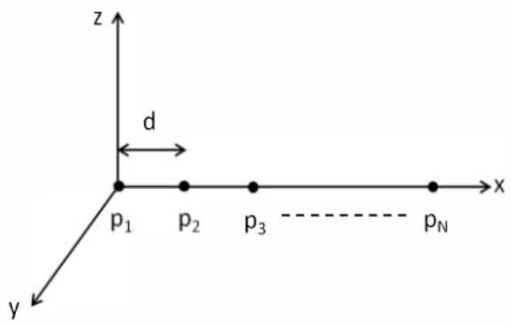
y
Fig. 2. Unifonn linear array with
N
= 21 elementsobjective value -Tr{
A�tt1}
is less than a predefined target objective valueOt,
then the multiplier at iteration i + 1 is up dated as(H1
+---IL(i,
where 0 < fL < 1 is the parameter controlling the convergence rate of the algorithm. After finite number of iterationsNiter
or the difference between energy ratio of highest singular value ofA�Pt
between two consecu tive iterations, i.e.,I
2N
2N
I
r(i) =
aU
�
a� - al-1
/
�
a�-l
(11 )is smaller than a certain threshold v, iterations are terminated
and the final solution of (5) is obtained as:
(12) Corresponding complex antenna weight vector is given by
(13) where
W
is anN
x2N
matrix composed of all zeros exceptW(n, n)
= 1,W(n,
N
+n)
=j, Vn
= 1,... , N.
If thevalue of the cost function in (7) evaluated at the optimal so lution
A�Pt
at the final iteration is greater than -N,
then the complex antenna weightsa�, n
= 1,... , N
do not satisfy thepower constraint in (2). Hence, weights are finally normalized as:
(14) In Algorithm-I, proposed iterative method is summarized. In the next section experimental results demonstrating the per formance of the proposed method will be provided.
4. EXPERIMENTAL RESULTS
To investigate the perfonnance of the proposed method, we used a uniform linear array with
N
= 21 elements shown inFig.2. Element positions are Pn =
[
d(n
- 1) , 0,OlT, n
=1,
... , N.
Inter element spacing is d = 0.4'\, where ,\ is30�---�---�==========� 20 10 � 0 ..Q � <:L -10 B' cD !:[ -20 -30 -40 -50
�---�---�---�----�
o 50 100 <p (8=0 cut) [Degree] 150Fig. 3.
B
= 0 degree cut of the power pattern for steering direction
(Bp
= 0,rPp
= 90)degree computed using the weightsfound after iteration i = 1 (solid) and i = 20(dashed-dotted)
the wavelength, and operating frequency is chosen as
f
=2GHz. As design constraints, we allow 5dB power reduction in the steering direction
(5m
= 10 logN
2
- 5 dB) and require23 dB side lobe suppression
(5s
= 10 logN
2
- 23 dB). Thebeamwidth measured at 23 dB below the maximum power level (10 log
N
2
) around the steering direction is constrained to be less than 15 degree in azimuth. All the antenna elements are required to operate at 1 Watt power level(5p
= 1). Theproposed method in Algorithm-l is initialized with parame ters
Niter
= 20, V = 0.01 for steering direction in azimuthrPp
= 90 degree and in elevationBp
= 0 degree. For solvingthe SDP in (6), we used CVX, a package for specifying and solving convex programs [10].
After the first iteration, optimal value of the SDP in (7) is found to be -21. However, since the provided solution is not rank-I, the total power of the antenna elements is
IIal112
= 8,much smaller than 21. Hence the normalized coefficients
&
1
differ from the computed onesa1
much. In Fig.3, elevationB
= 0 cut of the power pattern generated by using the normalized complex weight vector after iteration i = 1 (
&
1
) isplotted (solid). As observed, resulting beam pattern do not satisfy the design constraints. After 20 iterations, still the op timal value of the SDP in (7) is computed to be -21, the opti mal solution matrix
A;gt
is nearly rank-l and the total power of the antenna elements isIIa20112
= 20.88. Hence the normalized coefficients
&20
are nearly the same witha20.
The resulting pattern after iteration 20 is plotted (dashed-dotted). As observed, all the design constraints are satisfied.In FigA, the ratio of the largest singular value of the opti mal solution matrix
A�Pt
of (7) to the sum of all its singular values as a function of iteration numberi, i.e.,all
L��l
a�,
is plotted. As observed, at iteration i = 20, the solution ma0.2
O L---�---L---�---�
5 10 15
Iteration Number Ii] 20
Fig. 4. Ratio of the largest singular value of the optimal solu tion matrix
A�Pt
of (7) to the sum of all its singular values as a function of iteration number i.20
2
---e---After iteration 1 --+--After iteration 3
4 6 8
Singular Value Index 10
Fig. 5. 10 largest singular values of
A�Pt
at iteration i = 1,i = 3, i = 10.
occupies most of its energy. Note that, as the iteration num ber increases, this ratio increases, demonstrating the converge behaviour of the proposed iterations. In Fig.5, 10 largest sin gular values of
A�Pt
at iteration i = 1, i = 3, i = 10 are plotted. In the first iteration, singular values
A;pt
have a small decay rate. After iteration 3, singular values have a faster de cay. At iteration 20, most of the energy is accumulated in the first singular value and the remaining ones are very close toO. Hence, the proposed iterations provided a rank. -1 solution to (7).
5. CONCLUSIONS
In this work, we proposed a novel iterative method for the phase-only beam synthesis problem. First, desired weights are formulated to be the solution of a non-convex QCQP.
Then, the QCQP is relaxed to a convex SDP. Proposed it erations constrain the optimal solution of the SDP to have fast decaying singular values. After a few iterations, ob tained solution is observed to be nearly rank-I. Conducted experiments indicate that, proposed method has a certain con vergence behaviour and can successfully design beam shapes with desired characteristics by only using element phases.
6. REFERENCES
[1] R. J. Mailloux, "Phased array antenna handbook, "
Artech House, 2005.
[2] D.H. Werner D.W. Boeringer, "Particle swarm opti mization versus genetic algorithms for phased array syn thesis, " IEEE Transactions on Antennas and Propaga tion, vol. 52, pp. 771-779, March 2004.
[3] G.K. Mahanti and A. Chakrabarty, "Phase-only and amplitude-phase synthesis of dual-pattern linear an tenna arrays using floating-point genetic algorithms, "
Progress in Electromagnetic Research, vol. 68, pp. 247-259, 2007.
[4] G.G. Rassweiller C.A. Baird, "Adaptive side lobe nulling using digitally controlled phase-shifter, " IEEE Transactions on Antennas and Propagation, vol. AP-24, pp. 638-649, September 1976.
[5] H. Steyskal, "Simple method for pattern nulling by phase perturbation, " IEEE Transactions on Antennas and Propagation, vol. no. 1, pp. 163-166, January 1983. [6] R. Vincenti R. Giusto, "Phase-only optimization for generation of wide deterministic nulls in the radiation pattern of phased arrays, " IEEE Transactions on Anten nas and Propagation, vol. AP-31, pp. 814-817, Septem ber 1983.
[7] R.L. Haupt, "Phase-only adaptive nulling with a genetic algorithm, " IEEE Transactions on Antennas and Prop agation, vol. 45, pp. 1009-1015, June 1997.
[8] G. Panariello a.M. Bucci, G. Mazzarella, "Reconfig urable arrays by phase-only control, " IEEE Transac tions on Antennas and Propagation, vol. 39, pp. 919-925, 1991.
[9] A.M. So Y. Ye Z. Luo, W. Ma and S. Zhang, "Semidef inite relaxation of quadratic optimizaiton problems, "
IEEE Signal Processing Magazine, vol. Special Issue on Convex Opt. for SP, pp. 1-14, May 2010.
[10] Inc. CVX Research, "CVX: Matlab software for disciplined convex programming, version 2.0," http://cvxr.com/cvx,2012.