i
EXPERIMENTAL DEMONSTRATION OF
TRANSMISSION ENHANCEMENT
THROUGH SUBWAVELENGTH APERTURES
AT MICROWAVE FREQUENCIES
A THESIS
SUBMITTED TO THE DEPARTMENT OF ELECTRICAL AND ELECTRONICS ENGINEERING
AND THE GRADUATE SCHOOL OF ENGINEERING AND SCIENCES OF BILKENT UNIVERSITY
IN PARTIAL FULLFILMENT OF THE REQUIREMENTS FOR THE DEGREE OF
MASTER OF SCIENCE
By
DAMLA ATEŞ
June 2012
ii
I certify that I have read this thesis and that in my opinion it is fully adequate, in scope and in quality, as a thesis for the degree of Master of Science.
Prof. Dr. Ekmel Özbay (Supervisor)
I certify that I have read this thesis and that in my opinion it is fully adequate, in scope and in quality, as a thesis for the degree of Master of Science.
Prof. Dr. Ayhan Altıntaş
I certify that I have read this thesis and that in my opinion it is fully adequate, in scope and in quality, as a thesis for the degree of Master of Science.
Assoc. Prof. Dr. Hamza Kurt
Approved for the Graduate School of Engineering and Sciences:
Prof. Dr. Levent Onural
iii
ABSTRACT
EXPERIMENTAL DEMONSTRATION OF
TRANSMISSION ENHANCEMENT THROUGH
SUBWAVELENGTH APERTURES
AT MICROWAVE FREQUENCIES
Damla Ateş
M.S. in Electrical and Electronics Engineering Supervisor: Prof. Dr. Ekmel Özbay
June 2012
Metamaterials are artificial materials with novel electromagnetic characteristics. They are used in many applications including imaging, super lenses, cloaking, transmission enhancement, beaming and recently in nano applications. One of the major building blocks is the split ring resonators (SRR). We can construct metamaterials by using a single or an array of the SRRs.
In this thesis, enhanced transmission through subwavelength apertures, which is one of the applications of metamaterials, is obtained by using various split ring resonators configurations. We demonstrated transmission enhancement with Connected Split Ring Resonators (CSRRs), Omega-like Split Ring Resonators and Stack-like Split Ring Resonators through circular and rectangular subwavelength apertures experimentally and numerically at the microwave fre-quencies. We report the highest experimental transmission enhancement results in the literature so far. Besides high factors, we also obtained multi-peak reso-nant characteristics with Stack-like SRR designs.
Furthermore, we analyzed these various SRR samples numerically in order to understand the resonance behavior. We also discuss the effects of shorting the loops, omitting the components of the SRRs and aperture geometry to the reso-nance frequency. Finally, we applied Tight Binding methods to analyze the mul-ti-peak characteristics of the Stack-like SRR design.
Keywords: Metamaterial, Split Ring Resonator, Transmission Enhancement,
iv
ÖZET
MİKRODALGA FREKANSLARINDA
DALGABOYU-ALTI DELİKLERDEN OLAĞANÜSTÜ
ELEKTROMANYETİK GEÇİRGENLİĞİN DENEYSEL
GÖSTERİMİ
Damla AteşElektrik ve Elektronik Mühendisliği Bölümü Yüksek Lisans Tez Yöneticisi: Prof. Dr. Ekmel Özbay
Haziran 2012
Metamalzemeler, farklı elektromanyetik karakteristiğe sahip yapay yollarla elde edilen malzemelerdir. Metamalzemeler, görüntüleme, süper lensler, görünmezlik pelerini, olağanüstü elektromanyetik geçirgenlik, nanoteknolojik yapılar gibi birçok alanda kullanılırlar. Metamalzemelerin en küçük yapıtaşlarından biri de
Ayrık Halkalı Rezonatörlerdir (SRR). Bu ayrık halkalı rezonatörleri tek başlarına
ya da bir dizi halinde kullanarak çeşitli metamalzemeler elde edebiliriz.
Bu çalışmada, Bağlı Ayrık Halkalı Rezonatörler, Omega tipi Ayrık Halkalı Rezonatörler ve Sıralı Ayrık Halkalı Rezonatörler yardımıyla dairesel ve dikdörtgensel dalga-boyu altı deliklerden, mikrodalga frekanslarında olağanüstü elektromanyetik geçirgenlik sağladık. Deneylerde elde ettiğimiz sonuçlar şu ana kadar elde edilmiş sonuçların hepsinden daha yüksektir. Yüksek elektromanyetik geçirgenliğin yanısıra, Sıralı Ayrık Halkalı Rezonatörler sayesinde daha geniş bir band aralığında geçirgenlik kazandık.
Deneylerin yanısıra elektromanyetik geçirgenliğe sebep olan resonansları anlamak için nümerik analizler yaptık. Nümerik analizlerin deneysel sonuçlarla örtüştüğünü gözlemledik. Son olarak, bu yapılarda çeşitli geometrik değişikliklerle analizler yaptık. Sıralı Ayrık Halkalı Rezonatörler’in elektromanyetik geçirgenliğini anlamak için Tight Binding methodunu kullandık.
Anahtar kelimeler: Metamalzemeler, Ayrık Halkalı Rezonatörler, Olağanüstü
v
Acknowledgements
First of all, it is my pleasure to express my deepest gratitude and respect to my supervisor Prof. Ekmel Özbay for his invaluable guidance, ideas, encour-agement and endless support during my thesis and my entire academic life. He supported me at every single stage of my academic career and gave me a chance to make dreams come true.
I would like to thank to the members of my thesis committee, Prof. Ayhan Altıntaş and Assoc. Prof. Hamza Kurt for their guidance and commenting on the thesis.
I am very lucky to be a member of Nanotam, where I found best friends and colleagues. I would like to thank Özgür Çakmak, Evrim Çolak, and Andriy Serebryannikov for their help and contributions to joint works during my thesis. Especially, I would like to thank my close friends who are also the greatest of-fice mates, Semih Çakmakyapan and Neval Cinel for their intellectual and mor-al support during my research and thesis. They helped and supported me when-ever I struggle. Also, I would like to thank Gülesin Eren, Serdar Öğüt for being such good friends and Nursel Aşıcı, Gamze Seymenoğlu and to all Nanotam members.
I am very grateful to my instructors, especially Prof. Hitay Özbay, Assoc. Prof. Aykutlu Dana, Prof. Orhan Aytür and all the other EEE faculty members for their assistance during my undergraduate and graduate studies. I would like to thank to my friends Erdem Ulusoy and Olgu Çalımlı, and senior Mürüvet Parlakay and all my friends in EEE department.
I owe thanks to my friends Özlem İskender, Seher Acer, Türkiz Erdoğan, Dilce Gözüyaşlı, Elif Demirli, Gizem Altay, and Ayşe Yeşil for their endless support and being such good friends to me. Also, I especially thank to my late friend Deniz Aksoy for his intellectual and moral support and pure friendship. We miss you so much and we will always remember you.
vi
Special thanks go to my mother, my father, my grandmother, and to all of my family for their boundless love, support, encouragement and understanding dur-ing my research and thesis. I am a very lucky person to have a great family.
Finally, I would like to thank to Üstun Özgür for his endless support, help and love.
vii
viii
Table of Contents
List of Figures... ix
List of Tables ... xii
Chapter 1 Introduction... 1
Chapter 2 Theoretical Background ... 4
2.1 Split Ring Resonators ... 4
2.2 Transmission Enhancement Phenomenon ... 5
Chapter 3 Transmission Enhancement using Connected Split Ring Resonators ... 8
3.1 CSRR Design and Experimental Environment ... 9
3.2 Measurement and Simulation Results ... 13
Chapter 4 Transmission Enhancement using Omega-like Split Ring Resonators ... 24
4.1 Omega-like Split Ring Resonator designs ... 25
4.2 Experimental Environment ... 26
4.3 Transmission Enhancement Results ... 27
4.4 Verification of Experiments through Simulations... 30
4.5 Physical Analysis of Transmission Enhancement via Omega-like SRRs ... 30
4.6 Parametrical Analysis that Strengthen the Physical Observations ... 32
Chapter 5 Transmission Enhancement using Stack-like Split Ring Resonators ... 37
5.1 Multi-Stack Design and SRR configuration ... 38
5.2 Experimental Environment of the Stacked Metal Screens with SRRs and Transmission Spectra ... 41
5.3 Physical Analysis and Tight Binding Calculations ... 48
Chapter 6 Conclusion ... 54
ix
List of Figures
Figure 2.1: Schematics of a single SRR with geometric parameters of splits, metal width and radius [12]. ... 4 Figure 2.2: Diffraction and transmission spectrum of the light through subwavelength aperture
(Genet et al.) [15]. ... 5 Figure 3.1: SRR coupled subwavelength aperture in the metallic screen design introduced by
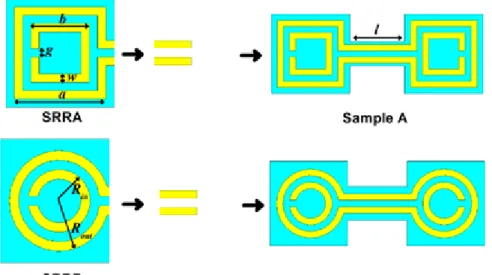
Aydin et al. [38] ... 8 Figure 3.2: Single SRR configurations (a) Rectangular SRR, SRRA and (b) Circular SRR,
SRRB. ... 9 Figure 3.3: SRRA and SRRB samples in order to design CSRR samples: Sample A and Sample
B ... 10 Figure 3.4: Simulated Transmission spectra of (a) SRRA and Sample A, (b) SRRB and Sample
B. ... 11 Figure 3.5: Sample A incorporated in the aperture. ... 12 Figure 3.6: Design of the experimental setup. ... 13 Figure 3.7: Measured Transmitted Intensity through (a) Sample A (solid red line) and Single
Aperture (solid black line) and (b) Sample B (solid red line) and Single Aperture (solid black line). ... 14 Figure 3.8: Calculated Enhancement Factors from measurement results for (a) Sample A and (b) Sample B. ... 15 Figure 3.9: Fabricated Samples (a) Sample A, (b) Sample B and (c) Experimental setup. ... 15 Figure 3.10: Simulated Transmission Intensity Spectra for (a) Sample A (solid red line) and
Single Aperture (solid black line), (b) Sample B (solid red line) and Single Aperture (solid black line) ... 16 Figure 3.11: Simulated Transmitted Electric Fields Results corresponding to transmission
through Single Aperture incorporated with Sample B (dashed red line), Inner Rings shorted Sample B (solid green line), and Outer Rings shorted Sample B (dashed black line). ... 17 Figure 3.12: STE factor for various radii in the range 2.4-7 mm where the black dots are the
numerical results and red line is experiment organized by Cakmak et al. [39] ... 19 Figure 3.13: (a) Simulated transmitted electric field through Big CSRR in the small aperture
(black line) and Big CSRR in the big aperture (red line), (b) Simulated Field Enhancement of Big CSRR through the small aperture (black line) and the big aperture (red line) ... 20
x
Figure 3.14: (a) Simulated transmitted electric field of Sample A (red line), Sample A PRL design (green line) and Sample A without Connecting bars (b) Simulated Field
enhancement of of Sample A (red line), Sample A PRL design (green line) and Sample A without connecting bars ... 21 Figure 3.15: (a) Induced surface currents when the CSRR is excited, (b) Field localization
around the aperture, Electric field localization in the vicinity of the aperture when the CSRR is (c) without connecting bars, (d) with connecting bars. ... 22 Figure 4.1: Omega samples when (a) deposited both sides, (b) an array that includes three
Omega Samples, (c) a periodic array in both sides, (d) example of a transmission
spectrum. ... 24 Figure 4.2: a) Schematic of the designed omega-like split-ring resonators from the front side
where the parameters are r = 3 mm, w = 1 mm, and l = 4 mm. (b) Designed omega-like split ring resonator from the back side. (c) Copper screen with omega-like split-ring resonators inserted in the circular aperture where the dimensions are h = 7.5 mm and L = 700 mm. (d) Copper screen with omega-like split-ring resonators inserted in the rectangular aperture ... 26 Figure 4.3: Schematic demonstration of the transmission enhancement experiments using
waveguide antennas and HP8510C network analyzer. ... 27 Figure 4.4: (a) Experimental and (b) simulation results of the transmission intensity (dB) through
the circular aperture (c) experimental and (d) simulation results for the rectangular aperture (solid black line is for the single aperture, solid red line is for the omega-like split-ring resonators inserted across aperture.) ... 28 Figure 4.5: Enhancement factor in the case of the omega-like split-ring resonators inserted (a)
across the circular aperture and (b) across the rectangular aperture. ... 29 Figure 4.6 Surface current density (a) at 3.15 GHz (even mode operation) where the first
enhancement peak occurs, (b) at 3.95 GHz (odd mode operation) where second enhancement peak occurs, (c) at 5.00 GHz (non-resonant frequency) where no
enhancement occurs. ... 31 Figure 4.7 (a) Difference of the transmission through circular and rectangular apertures and (b)
difference of the enhancement factor when omega-like split-ring resonators are inserted across circular and rectangular apertures... 32 Figure 4.8: Electric Field Distribution maps of the (a) Double-sided Omega-like SRR across the
rectangular aperture at 3.95 GHz (above), 5.00GHz (below), (b) Single-sided Omega-like SRR across the rectangular aperture at 3.95 GHz (above), 5.00GHz (below), (c)
Rectangular Aperture without Omega-like SRR at 3.95 GHz (above), 5.00GHz (below). 33 Figure 4.9: (a) Transmission characteristics of Double-sided (Solid Red), Single-sided
xi
Electric Field Distribution Maps collected at 3.95 GHz (Resonance Frequency)
respectively. ... 35 Figure 4.10: Field Distribution Maps (a) 0.1λ away (b) 0.5λ away, (c) 0.7λ away from
like SRR, and (d) Normalized transmitted intensity versus distance away from the Omega-like SRR in terms of operational wavelength. ... 36 Figure 5.1: Simulation environment of Four Stacked-Four SRR design (a) from the side, (b)
from the front perspective. ... 38 Figure 5.2: (a) and (b) various configurations of SRR coupled single aperture designed by
Aydin et al. and Cakmak et al. (c) SRR design from the front view [38, 39]. ... 39 Figure 5.3: SRR design that is used to couple the stacks. ... 40 Figure 5.4: (a) SRR cover the half of the aperture, (b) zoomed view from the front side, and (c)
zoomed view from the back side. ... 41 Figure 5.5: Transmission spectra of the SRR incorporated single aperture (red solid line) and
single aperture (black solid line). ... 42 Figure 5.6: Transmission spectra of the two Stacks with two SRRs (red solid line) and two stacks without SRRs (black solid line). ... 43 Figure 5.7: Transmission spectra of the three Stacks with three SRRs (red solid line) and three
stacks without SRRs (black solid line). ... 44 Figure 5.8: Transmission spectra of the four Stacks with four SRR (red solid line) and four
stacks without SRRs (black solid line). ... 45 Figure 5.9: Calculated enhancement factors of single stack-SRR (solid black line), two
stacks-two SRRs (dashed red line), three stacks-three SRRs (solid blue line), four stacks-four SRRs (solid green line). ... 46 Figure 5.10: Simulated Transmission Spectra of single stack-SRR (solid black line), two
stacks-two SRRs (dashed red line), three stacks-three SRRs (solid blue line), four stacks-four SRRs (solid green line). ... 47 Figure 5.11: Simulated Transmission spectrum of the ten stack-ten SRRs system with showing
xii
List of Tables
Table 5.1: Calculated and measured values of resonant frequencies for the Three Stack –Three SRR system. ... 50 Table 5.2: The calculated and simulated values of resonant frequencies for the Three Stack –
1
Chapter 1
Introduction
Electromagnetism has taken a fundamental role in our lives. Electromagnetic applications are used widely in many areas including imaging, antenna engineer-ing, perfect lenses, cloakengineer-ing, optics and photonics.
One of the main research topics in electromagnetism is electromagnetic prop-agation. To improve electromagnetic propagation, antennas and waveguides, have been designed. Propagation characteristics such as transmission, reflection and diffraction are the major research issues in this topic. Depending on goals, their effects need to be improved or reduced.
Another significant topic in electromagnetism is the light matter interaction. There is an interaction between the matter and electromagnetic wave that domi-nates the propagation characteristics. Therefore; one needs to understand the light-matter or wave-matter interaction to control electromagnetic propagation.
The magnetic response of a material to a wave is determined by its dielectric permittivity (ε) and magnetic permeability (μ). For materials found in nature, ε
and μ are usually positive. However, their responses can be changed by
rede-signing them artificially. These redesigned materials are defined as
metamaterials. The term “meta” is adopted from Greek which means “beyond”.
Similar to materials consist of atoms, the basic building blocks of metamaterials are meta-atoms that are smaller than the operational wavelength. Metamaterials are one of the most interesting artificial materials nowadays be-cause of their controllable electromagnetic parameters (ε and μ) obtained by
modifying the geometry of their designs. Their parameters can be adjusted to desired negative and positive values.
Even before the term “metamaterials” was defined, electromagnetic parame-ters had already become a research topic. In 1968, Russian physicist Victor
CHAPTER 1. INTRODUCTION
2
Veselago proposed that ε and μ can in fact be negative in his famous paper “The
electrodynamics of substances with simultaneously negative values of ε and μ” [1]. Veselago named such materials “Left-Handed Materials”. Less than half a decade later, this phenomenon was realized by another renowned theoreti-cal physicist Sir John Pendry, who showed how such materials could be con-structed [2]. Electromagnetic parameters determine the index of refraction and their simultaneously negative behavior generates a negative index of refraction.
For guiding and beaming the incident electromagnetic waves, beside metamaterials, other optical applications such as photonic crystals, metallic grat-ing structures and fiber-modeled waveguides are used. Furthermore; to obtain strong waveguiding and beaming through transmission, plasmonic effects can be exploited [3-5].
Metamaterials with these magical properties have gained an increasing atten-tion in the scientific community and have found use in many applicaatten-tions in-cluding perfect lenses that are capable of imaging subwavelength sized sub-stances with a high resolution, magnifying hyper lenses, and cloaking applica-tions that work in the microwave regime [6-9]. In addition, metamaterials are scalable materials that we can tailor for the desired frequency of range such as radio, microwave, millimeter-wave, infrared (IR), visible wavelengths [10, 11]; so they have a wide range of applicability.
In this research, we investigate alternative ways to obtain a better and con-trollable transmission via various metamaterial configurations. We seek the op-timal design that enhances transmission and surpasses the results reported in lit-erature. The principle reason that we use metamaterials is their easily tailored and characterized. Hence, we can anticipate the results and demonstrate their validity through the experiments at the desired regime. We also verify the exper-iments with numerical analysis and explain their physical behind them.
In Chapter 2, we introduce the main building blocks of metamaterials which called Split Ring Resonators (SRRs). We also explain their magnetic resonance behavior, introduce the transmission enhancement phenomenon and discuss the previous related work in the literature.
CHAPTER 1. INTRODUCTION
3
In Chapter 3, we propose a way to increase the transmission and obtain an enhancement. We describe our novel SRR design called Connected Split Ring Resonators (CSRR). We demonstrate the transmission enhancement by experi-ments and numerical analysis. We analyze further why transmission enhance-ment occurs.
Chapter 4 is similar to Chapter 3, however, instead of CSRR, we use another metamaterial that we designed called Omega-like SRR. Using this design, we show that a greater transmission enhancement occurs.
In Chapter 5, our aim is to obtain a transmission enhancement in a wide-range multi-peak resonance system. To achieve this, we design a stack-like SRR structure in which large metal plates with SRRs are placed in succession and aligned. Using this design, we obtain an enhancement in a broader bandwidth. Finally, we apply the Tight Binding (TB) approximation to analyze the physical origins of the enhanced multi-peak resonance system.
4
Chapter 2
Theoretical Background
In this chapter, we briefly introduce the Split Ring Resonators and transmission enhancement phenomenon.
2.1 Split Ring Resonators
In 1999, Pendry et al. proposed an alternative way to change the magnetic per-meability to negative by designing a periodic array of conducting particles. Since then these periodic arrays also known as SRRs became a hot topic.
To understand the resonant behavior of the SRRs, we should consider its de-sign first. The conventional SRR is shown in Figure 2.1 [12].
Figure 2.1: Schematics of a single SRR with geometric parameters of splits, metal width and radius [12].
In this design, the conducting wires acts as inductors; the splits and gaps as-sume capacitive roles (capacitors). From a circuit theory point of view, this LC composition creates a resonant behavior. Hence, the magnetic resonance gains negative and positive values around the resonance frequency.
The structure in Figure 2.1 is used as the unit cell of a periodic array. A single unit also has a resonant behavior, however, to have band gap more observable, we need to use a periodic array of this structure in three dimensions [13].
CHAPTER 2. THEORETICAL BACKGROUND
5
2.2 Transmission Enhancement Phenomenon
Electromagnetic power transmission through holes has been a significant re-search topic. The most significant contribution was done by H. Bethe. He con-sidered the case of power transmission through a small aperture drilled in an opaque or metallic screen. In 1944, he analyzed the relation between the trans-mission efficiency and the dimension of the aperture (radius, r) compared to op-erational wavelength (λ) [14]. He proposed that transmission efficiency is
pro-portional (r/ λ)4. Figure 2.2 shows the behavior that the Bethe has proposed [15]. As shown in the figure, the power transmission becomes extremely low at small apertures. However, it can be controlled in both intensity and frequency by modifying the geometry of the small aperture.
Figure 2.2: Diffraction and transmission spectrum of the light through subwavelength ap-erture (Genet et al.) [15].
Ebbesen and other scientists have since work on this topic that Bethe has started, trying to improve the efficiency of transmission [16]. Those studies, in which transmission has been enhanced beyond the limit proposed by Bethe, have been named “extraordinary transmission”. In those studies, an array of hole was drilled on a metallic screen. Due to surface plasmon phenomenon, more efficient transmission than Bethe’s predictions at specific frequencies was achieved. The extraordinary transmission topic gained an attention by other re-search groups and various results were obtained both theoretically [17-20] and experimentally [21-27].
CHAPTER 2. THEORETICAL BACKGROUND
6
Wave and metallic screen interaction was investigated from the surface plas-mon polariton point of view and the transmission efficiency was analyzed in this manner. It was showed that the surface plasmons of the metallic screen interact with the incident photons [24, 25, 27]. Especially if periodic designs are used the number of interactions increases because these interactions occur for every sin-gle subwavelength structure and hole each of which act like point sources and consequently, transmission efficiency increases. Finally it should be noted that, although periodic designs are more advantageous as shown, the transmission through single aperture still remains as a challenge and has been analyzed by other physicists [28-31].
It has been shown that it is also possible to support the surface plasmons by adding particular corrugations to the surfaces. In the first earlier studies, corru-gations were added to single apertures. It is possible to create a grating-like structure by adding periodic corrugations around these single apertures. The Bull’s eye design is an example of a corrugation-hole structure [4]. The studies showed that the transmission through the single aperture increases remarkably and the beaming can be controlled [3-5]. Later on, the same technique was ap-plied to other periodic designs [32, 33]. The incident beam is coupled to these periodic grooves or corrugations.
Pendry and his colleagues have also shown that the surface plasmons exist not only in the optical regime but also in the microwave frequencies as “spoof plasmons”. Spoof plasmons support the coupling that enhances transmission [34, 35].
After Pendry’s and Ebbesen’s observations regarding the corrugated surfaces, other scientists including Alu et al. and Marques et al. investigated the effect of using metamaterial slabs with SRRs as corrugations [36, 37]. Due to their epsi-lon-near-zero or mu-near-zero behavior and low diffraction nature, they could be the proper candidates for enhancing the transmission. However, both corruga-tions based and metamaterial based approaches depend on the coupling between the incident waves and propagating surface modes.
CHAPTER 2. THEORETICAL BACKGROUND
7
To overcome the limitations in the transmission enhancement phenomenon, Aydin et al. and Cakmak et al. designed an SRR coupled metallic screen config-uration [38]. Since the dimensions of the SRR are comparable to aperture which is subwavelength, this setup was extremely compact. They achieved 740-fold enhancement with guidance of the incident beam through the subwavelength aperture. Finally, Cakmak et al. discusses the physical origins of the enhance-ment by analyzing the surface currents in the vicinity of aperture [39].
8
Chapter 3
Transmission Enhancement using
Connected Split Ring Resonators
In this chapter, we propose an alternative way to increase the transmission and obtain an enhancement. We designed a new type of SRR called Connected Split Ring Resonators (CSRR). We demonstrate the transmission enhancement by ex-periments and numerical analysis. We also analyze the physical origins of transmission enhancement.
Although previous designs (see [38, 39]) propose high enhancement results, our design surpasses those results. Another difference with the previous studies is the orientation of the resonator: instead of covering the sub-wavelength aperture as shown in Figure 3.1, we inserted the split-ring resonator across the aperture as shown in Figure 3.5.
Figure 3.1: SRR coupled subwavelength aperture in the metallic screen design introduced by Aydin et al. [38]
CHAPTER 3. TRANSMISSION ENHANCEMENT USING CSRRS
9
3.1 CSRR Design and Experimental
Environ-ment
At the beginning, we used two configurations as building blocks: rectangular SRRs in Sample A, and circular SRRs in Sample B respectively. (See Figure 3.2) Then, we came up with a design by combining two conventional split-ring reso-nators facing each other, through metal connecting bars as depicted in Fig-ure 3.3 (a) and (b).
Figure 3.2: Single SRR configurations (a) Rectangular SRR, SRRA and (b) Circular SRR, SRRB.
The SRR samples are deposited on one side of a dielectric printed circuit board (PCB) which is used as the substrate material for these SRR samples. The PCB thickness is 1.6 mm which is deposited with a 30 μm copper. The design parameters are the following: split width g = 0.5 mm, which is the same for inner and outer ring (Figure 3.3 (a)), copper width w = 0.5 mm, and the separation dis-tance (length of the connecting bars) l = 5.5 mm for both SRR configurations,
Rout = 3 mm, and Rin = 1.75 mm. So, we obtained an opposed pair of SRRs with
CHAPTER 3. TRANSMISSION ENHANCEMENT USING CSRRS
10
Figure 3.3: SRRA and SRRB samples in order to design CSRR samples: Sample A and Sample B
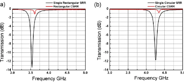
We first simulated the SRR and CSRR designs that are shown in Figure 3.2 and Figure 3.3 to characterize their transmission behavior and adjust the magnetic resonance frequency by changing the dimensions of the structures. We performed several simulations with these SRR and CSRR designs by using CST Microwave Studio. In order to determine the resonance frequencies, we applied periodic boundary conditions and plane wave excitation where the electric field (E-Field component) is parallel to the CSRR splits and magnetic field (H-Field) is perpen-dicular to the plane of CSRRs.
We obtained resonance frequencies for Rectangular CSRR (Sample A) at 3.61 GHz, Single Rectangular SRR (Single Sample A) at 3.53 GHz, Circular CSRR (Sample B) at 4.34 GHz, and lastly, Single Circular SRR (Single Sample B) at 4.26 GHz which are all between the ranges of interest (3-6 GHz). The transmission spectra are shown in Figure 3.4.
CHAPTER 3. TRANSMISSION ENHANCEMENT USING CSRRS
11
Figure 3.4: Simulated Transmission spectra of (a) SRRA and Sample A, (b) SRRB and Sample B.
In addition to designing the CSRRs, we designed the metallic plate that will be used for large screen during the experiments. The metallic screen is a 50 cm x 50 cm copper plate with a thickness of 0.5 mm. The metallic screen was chosen as large as possible to reduce the effects of the diffraction from the edges. In the middle of the plate, we drilled a rectangular aperture with a width of 3 mm and height of 7.5 mm. This aperture size is smaller than the other reported aperture sizes in literature. [38, 39]. (See Figure 3.5)
CHAPTER 3. TRANSMISSION ENHANCEMENT USING CSRRS
12
Figure 3.5: Sample A incorporated in the aperture.
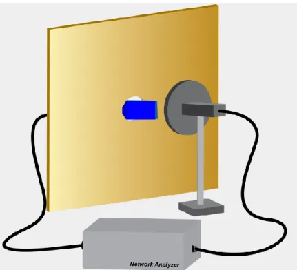
Next we started our experiments. During the experiments, we used conven-tional waveguide antennas with the operating frequency between 3-6 GHz. These antennas were connected to an HP8510C Network Analyzer as shown in Fig-ure 3.6. The distance between the transmitter and receiver antennas is 8 cm. The transmitter antenna is placed 0.2 mm away from the copper plate to reduce the diffraction effects, since diffraction from the edges of antennas are highly observ-able.
CHAPTER 3. TRANSMISSION ENHANCEMENT USING CSRRS
13
Figure 3.6: Design of the experimental setup.
3.2 Measurement and Simulation Results
At the first stage, we calibrated the network analyzer and measured the back-ground noise without metallic plate and CSRR samples. We placed electrically large Copper plate without inserting the CSRR between the transmitter and re-ceiver, with the distance given in the previous section.
Then we performed our first actual measurement by using the metallic plate that has a single aperture without inserting CSRR. We performed the next meas-urement by inserting Sample A across the rectangular aperture which is perpen-dicular to the plane of the metallic plate. At the final stage, similarly, we per-formed the third measurement by inserting the Sample B into the rectangular ap-erture. We compared the differences between these three cases.
The “enhancement factor” is calculated by dividing the linear transmission values of CSRR incorporated with metallic plate to the linear transmission values of metallic plate without CSRR, for every frequency point within the bandwidth of interest.
CHAPTER 3. TRANSMISSION ENHANCEMENT USING CSRRS
14
Enhancement factor =
(1)
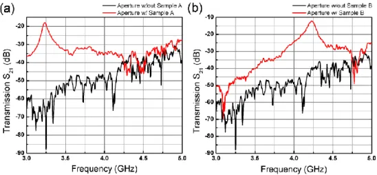
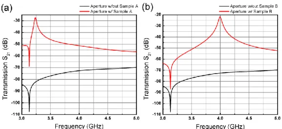
The measured transmission results are depicted in Figure 3.7 and enhancement results are depicted in Figure 3.8. According to Figure 3.7, we observed that a single peak occurs at a particular frequency for the case of CSRR incorporated with metallic plate. The peak is the evidence of the transmission enhancement phenomenon. The experimental setup and the fabricated structure are also shown in Figure 3.9.
Figure 3.7: Measured Transmitted Intensity through
(a) Sample A (solid red line) and Single Aperture (solid black line) and (b) Sample B (solid red line) and Single Aperture (solid black line).
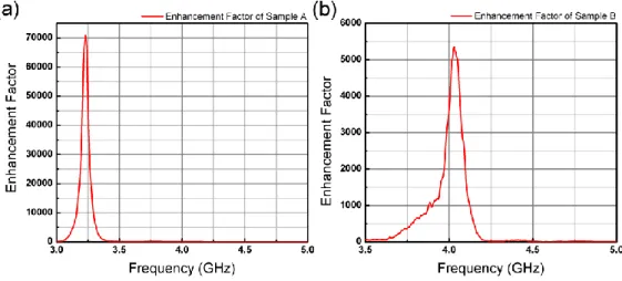
The enhancement results are shown in Figure 3.8 (a) and (b) with CSRR Sam-ple A and CSRR SamSam-ple B. For the case of SamSam-ple A; we observed more than 70,000-fold enhancement factor at 3.23 GHz whereas for sample B, we obtained more than 5,300-fold enhancement at 4.03 GHz through the subwavelength aper-ture with a width of λ/31 and a height of λ/12. These results are much higher than the previous reported results in the literature.
CHAPTER 3. TRANSMISSION ENHANCEMENT USING CSRRS
15
Figure 3.8: Calculated Enhancement Factors from measurement results for (a) Sample A and (b) Sample B.
CHAPTER 3. TRANSMISSION ENHANCEMENT USING CSRRS
16
After the successful experiments; we simulated the experimental environment once more by using CST Microwave Studio. We adopted the conventional wave-guide antenna from the experiments and designed them by being loyal to the same dimensions. We employed open boundary conditions in all directions. Also, we designed PCB with dielectric constant ε = 4 and a loss tangent δ = 0.01. We have used lossy copper for the metal plate.
As shown in Figure 3.10 the simulation results match with the experiment re-sults. We achieved to show that the enhancement peaks in the simulations and the actual experimental results are very similar. There is a minor shift in the peaks due to alignment of the antennas and CSRR in the aperture during the experi-ments, as well as fabrication issues of the CSRRs and metallic plates.
Figure 3.10: Simulated Transmission Intensity Spectra for (a) Sample A (solid red line) and Single Aperture (solid black line), (b) Sample B (solid red line) and Single Aperture (solid black line)
CHAPTER 3. TRANSMISSION ENHANCEMENT USING CSRRS
17
3.3 Physical Analysis and Observations
In this section, we analyze the transmission enhancement from different aspects and discuss the reasons why enhancement occurs.
The primary reason of transmission enhancement is the magnetic resonance of the SRRs. The electric fields in the loops of SRRs are coupled with each other. For our CSRR structure, the field is coupled within the loops and localized. Con-sequently, the incoming waves are guided from the incident side of the CSRR through the aperture to the exit side of the CSRR.
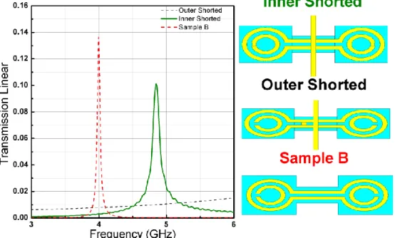
Figure 3.11: Simulated Transmitted Electric Fields Results corresponding to transmission through Single Aperture incorporated with Sample B (dashed red line), Inner Rings short-ed Sample B (solid green line), and Outer Rings shortshort-ed Sample B (dashshort-ed black line).
Here, we investigate the role of magnetic resonance when the loops of CSRRs are shorted. We aim to destroy the magnetic resonance when we short the loops of the CSRRs. Again, we used CST Microwave Studio simulation tool and em-ployed periodic boundary conditions as well as applying plane wave excitation. For this case we have chosen CSRR Sample B to analyze this effect. As
Fig-CHAPTER 3. TRANSMISSION ENHANCEMENT USING CSRRS
18
ure 3.11 represents the simulation results of the shorted and non-shorted CSRRs, shorting the outer rings destroys the magnetic resonance at 4.00 GHz whereas, shorting the inner rings only shifts the resonance frequency to higher frequencies. Hence, shorting the inner rings does not affect the existence of magnetic reso-nance at all. Since the outer ring still keeps its loop geometry, it dominates the magnetic resonance. Therefore, the outer ring is still responsible for the transmis-sion enhancement.
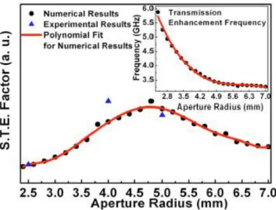
From a different point of view, we investigated the effects of the aperture size on the CSRR-aperture system. This study has been analyzed previously by Cakmak et al. [39]. In this previous study, the authors analyzed the effects of changing the aperture size on subwavelength transmission enhancement (STE) factors and frequency. In this paper, STE factor is defined as the multiplication of transmission enhancement with (R/λ) where R is the aperture radius and λ is the
operational wavelength.
STE factor = Enhancement factor * (2)
In that study, the resonator sizes were comparable to the subwavelength aper-ture size. The aperaper-ture radius ranged from 2.4 mm to 7 mm. They observed that the resonance frequency decreased as the radius of the aperture increased. Also, they found that the optimal aperture geometry has a radius of around 4.8 mm by using the STE factors. (See Figure 3.12) Finally, they concluded that any change in the geometry or size of the aperture could affect the resonance frequency.
CHAPTER 3. TRANSMISSION ENHANCEMENT USING CSRRS
19
Figure 3.12: STE factor for various radii in the range 2.4-7 mm where the black dots are the numerical results and red line is experiment organized by Cakmak et al. [39]
However in this study, we designed a resonator such that the resonance fre-quency is more stable with respect to the changes in aperture size and geometry. Our design consists of two copper plates each having a single aperture: Aperture 1 (Copper plate 1) and Aperture 2 (Copper plate 2). Aperture 1 has dimensions 1 mm x 2.5 mm whereas Aperture 2 has dimensions 3 mm x 7.5 mm width and height respectively.
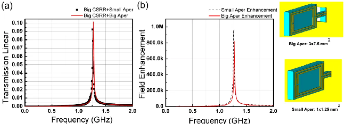
We designed another resonator with outer loop ring lengths 12.5 mm and inner loop lengths 10.5 mm. This new resonator is slightly larger than the previous CSRR. Figure 3.13 shows the apertures and this resonator. We simulated them by applying periodic boundary conditions and plane wave excitation. The measured transmission spectrum is shown in Figure 3.13. We observed similar amounts of enhancement factors at the same frequency when we use circular and rectangular apertures with the same large CSRR. Thus, the transmission frequency is inde-pendent of the aperture size, only the enhancement factor magnitude changes.
CHAPTER 3. TRANSMISSION ENHANCEMENT USING CSRRS
20
Figure 3.13: (a) Simulated transmitted electric field through Big CSRR in the small aper-ture (black line) and Big CSRR in the big aperaper-ture (red line), (b) Simulated Field
Enhance-ment of Big CSRR through the small aperture (black line) and the big aperture (red line)
As a final remark, we discuss the effect connecting bars on transmission en-hancement. In previous studies, researchers obtained enhancement by covering half of the aperture without having connecting bars [38, 39]. We used the similar design but instead of placing the SRR parallel to the plane of plate; we placed it perpendicular to the plane of plate. We also omitted the exit side of the CSRR Sample A. Single SRRs caused relatively smaller enhancement than factors the other CSRR cases. In [38] and [39], the researchers obtained a 740-fold en-hancement factor. However, in our case with CSRR, we achieved more than 70,000-fold enhancement.
CHAPTER 3. TRANSMISSION ENHANCEMENT USING CSRRS
21
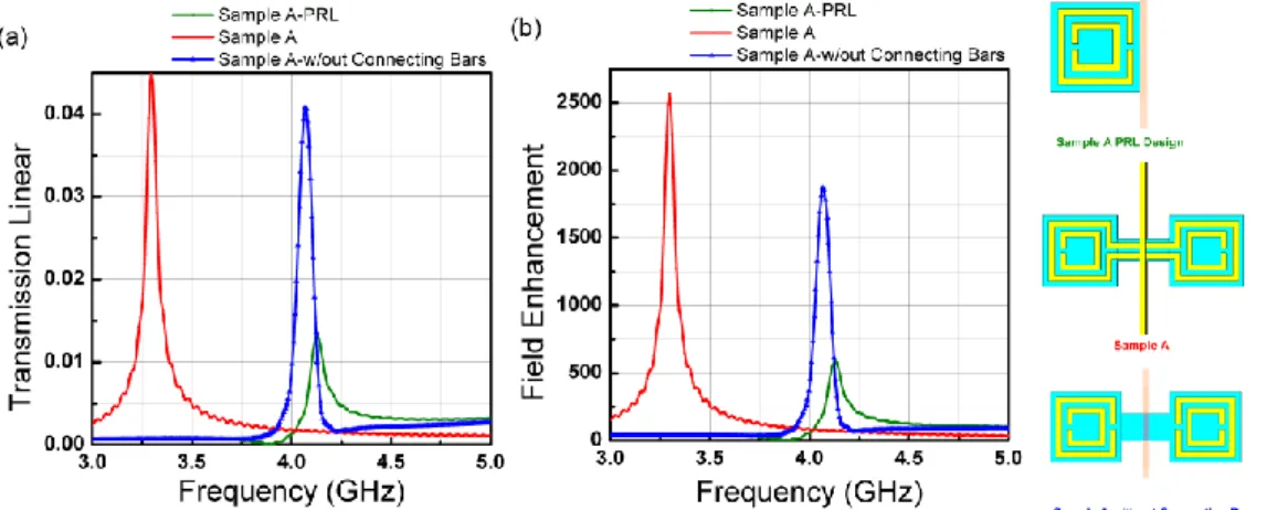
Figure 3.14: (a) Simulated transmitted electric field of Sample A (red line), Sample A PRL design (green line) and Sample A without Connecting bars
(b) Simulated Field enhancement of of Sample A (red line), Sample A PRL design (green line) and Sample A without connecting bars
Next, we simulated the CSRR without connecting bars. This structure has two SRRs but no connecting bars. We simulated this structure and analyzed both with CSRR Sample A, CSRR Sample A without connecting bars and single SRR as shown in Figure 3.14
.
We observe that CSRR Sample A and CSRR Sample A without connecting bars still have similar amount of enhancements with a slight frequency shift. On the other hand; single SRR has a relatively small enhance-ment. CSRRs without connecting bar have a better coupling than Single SRR due to exit side SRR. Also, due connecting bars, the CSRR inserted in the aper-ture system has a frequency independency from the aperaper-ture increasing and has an increased coupling.Furthermore, we analyzed the electric fields through the CSRRs, the connect-ing bars, the aperture and CSRRs without connectconnect-ing bars. As shown in Fig-ure 3.15 (a) the surface currents are distributed equally on both the input and output side of CSRR, which is the evidence of coupling between input and out-put sides. Figure 3.15 (b) demonstrates the highly localized electric fields around the aperture due to CSRRs. On the other hand, the second SRR is also highly coupled without connecting bars (Figure 3.15(c)). Single SRR might be useful to
CHAPTER 3. TRANSMISSION ENHANCEMENT USING CSRRS
22
have more E-Fields, however it poorly guides the E-Fields to the exit side SRR. Both input and output SRRs behave like transmitter and receiver antennas. We observed from Figure 3.15 (d) that the incoming fields are localized around the aperture and guided to the exit side SRR successfully via connecting bars. The exit side SRR is highly excited with the aid of these connecting bars.
Figure 3.15: (a) Induced surface currents when the CSRR is excited, (b) Field localization around the aperture, Electric field localization in the vicinity of the aperture when the
CSRR exists (c) without connecting bars, (d) with connecting bars.
As a conclusion, in this section, we presented an alternative approach that of-fers higher transmission enhancement results than the other reported ones. We first numerically characterized the CSRR configurations. Then, we obtained the transmission enhancement results experimentally. We verified them with the simulations once more by applying the experimental environment in the simula-tions. We achieved more than 70,000-fold enhancement at the single frequency as anticipated through subwavelength apertures (λ/31width x λ/12 height). We
CHAPTER 3. TRANSMISSION ENHANCEMENT USING CSRRS
23
finally analyzed the mechanism that generate or dominate the resonance fre-quency.
24
Chapter 4
Transmission Enhancement using
Omega-like Split Ring Resonators
The Omega-like particles were first introduced by Saadoum and Engheta in 1992 [40]. The authors showed these particles have bi-anisotropic and pseudo-chiral effects, so they are artificial materials. The omega particles were then analyzed by other physicists such as Tretyakov, Simovski and Sochova [41]. Omega particles were demonstrated as a successful candidate for left-handed metamaterials [42]. By using omega-like metamaterials, the intrinsic chirality of the medium can be eliminated and a moderate bandwidth can be obtained [43, 44]. To realize these characteristics, two omega-like resonators should be placed on opposing sides of a printed circuit board in opposite directions as shown in Figure 4.1 (a).
Figure 4.1: Omega samples when (a) deposited both sides, (b) an array that includes three Omega Samples, (c) a periodic array in both sides, (d) example of a transmission spectrum.
CHAPTER 4. TRANSMISSION ENHANCEMENT USING OMEGA-LIKE SRRS
25
Also, Aydin et al. experimentally and numerically demonstrated omega inclusions as a type of SRR and analyzed their characteristics [44].
There are some advantages to using Omega-like SRRs such as they are
low-loss and pseudo-chiral. Using these Omega designs in transmission enhancement
experiments, we can obtain even higher enhancement factors than those demon-strated in Chapter 3.
4.1 Omega-like Split Ring Resonator designs
Previously, we connected two conventional SRRs with connecting bars to use them for guidance and to obtain a better coupling at the output side of the metal-lic screen. In this case, similarly, we aim to use two omega-like SRRs to guide and couple the electric fields even more.
In this study, two omega-like SRRs as shown in Figure 4.1 are connected through their arms as shown in Figure 4.2 (a). We fabricated these samples by printing two identical particles (SRRs) in opposite directions on the two sides of a printed circuit board (PCB). The thickness of PCB (FR-4 dielectric board) is 0.5 mm with a 35μm copper deposition which can be seen in Figure 4.2 (a) and (b). In the previous case, CSRR was deposited and etched only one side of the PCB; in this case, we deposited and etched the Omega samples on both sides of the PCB.
The geometrical parameters of these Omega-like SRRs are as follows: the ra-dii of the loops are r = 3 mm, the width of the metal is w = 1 mm, the height of the PCB is h = 7.5 mm, single arm length l = 4 mm. (see Figure 4.2 (a) and (b))
We also designed the large copper plates that will be used in the experiments with dimensions 700 mm x 700 mm with a thickness of 0.5 mm. The first metal-lic plate (Plate 1) has a circular aperture in the middle of the plate with a radius of 3.75 mm whereas the second plate (Plate 2) has a rectangular aperture with di-mensions 3 mm x 7.5 mm width and height respectively as shown in Fig-ure 4.2 (c) and (d). The heights of the apertFig-ures are the same as the heights of the Omega-like SRR in order to cover the aperture vertically.
CHAPTER 4. TRANSMISSION ENHANCEMENT USING OMEGA-LIKE SRRS
26
Figure 4.2: a) Schematic of the designed omega-like split-ring resonators from the front side where the parameters are r = 3 mm, w = 1 mm, and l = 4 mm.
(b) Designed omega-like split ring resonator from the back side.
(c) Copper screen with omega-like split-ring resonators inserted in the circular aperture where the dimensions are h = 7.5 mm and L = 700 mm.
(d) Copper screen with omega-like split-ring resonators inserted in the rectangular aper-ture
4.2 Experimental Environment
During the experiments, we used metallic plate 1, plate 2 and Omega-like SRRs. The Omega samples were inserted across the apertures specified in the previous section.
We performed the experiments by using conventional waveguide antennas op-erating within the frequency range 3-6 GHz. The metallic plates incorporated with Omega samples are placed one by one between these antennas which were
CHAPTER 4. TRANSMISSION ENHANCEMENT USING OMEGA-LIKE SRRS
27
connected to an HP8510C Network Analyzer as depicted in Figure 4.3. Then, we collected the S21 data of each metal plate with and without Omega samples.
Figure 4.3: Schematic demonstration of the transmission enhancement experiments using waveguide antennas and HP8510C network analyzer.
4.3 Transmission Enhancement Results
We performed our first measurement with the copper screen having a circular ap-erture after calibrating the network analyzer with antennas. The distance between the transmitter and receiver antennas is 8 cm. The transmitter antenna is 0.2 mm away from the metal screen.
Next, using the same plate with circular aperture, we inserted the Omega-like SRR across the aperture and performed the second measurement. The results are shown in Figure 4.4 (a). After obtaining the two S21 parameters, we calculated the enhancement results regarding these S21 values. The enhancement is
calcu-CHAPTER 4. TRANSMISSION ENHANCEMENT USING OMEGA-LIKE SRRS
28
lated as the ratio of linearized S21 values of two cases for every frequency point between the ranges of interest. These calculations are for metallic plate with a circular aperture; then we applied the same procedures for the case of metallic plate with a rectangular aperture. Similarly, we obtained two transmission result and we calculated the enhancement factor for metallic plate with a rectangular aperture. The transmission measurement results are shown in Figure 4.4(b).
According to these results, we obtained two enhancement peaks for both cases as presented in Figure 4.5. In both cases, the first peak is at 3.15 GHz and the se-cond peak is at 3.95 GHz. Through circular aperture, we obtained 4,014-fold en-hancement at the first peak (3.15 GHz) and 9,262-fold enen-hancement at the second peak (3.95 GHz). For the case of rectangular aperture, we achieved a 20,780-fold enhancement at the first peak and 154,500-fold enhancement at the second peak. As we expected; these results are the highest results in the literature [38, 39, 45, 46].
Figure 4.4: (a) Experimental and (b) simulation results of the transmission intensity (dB) through the circular aperture (c) experimental and (d) simulation results for the rectangu-lar aperture (solid black line is for the single aperture, solid red line is for the omega-like
CHAPTER 4. TRANSMISSION ENHANCEMENT USING OMEGA-LIKE SRRS
29
Figure 4.5: Enhancement factor in the case of the omega-like split-ring resonators insert-ed (a) across the circular aperture and (b) across the rectangular aperture.
CHAPTER 4. TRANSMISSION ENHANCEMENT USING OMEGA-LIKE SRRS
30
4.4 Verification of Experiments through
Simula-tions
To validate the experiments, we numerically analyzed the system by using CST Microwave Studio. Initially, we modeled the two conventional waveguide antennas. We excited the antennas via waveguide ports. Open boundary condi-tions were employed for the environment throughout the simulacondi-tions.
We chose the relative dielectric constant ε = 4 and a loss tangent δ = 0.01 while modeling FR 4 PCB. The simulation results are shown in Figure 4.4 (c) and (d). As anticipated, the simulations provided better transmission results and higher enhancement factors due to various reasons such as diffractions at the edg-es of metallic screen which are cut off in simulations. Also, the dimensions of the samples are not exactly the same as the ones in the simulations due to manufac-turing constrains.
4.5 Physical Analysis of Transmission
Enhance-ment via Omega-like SRRs
We obtained two enhancement peaks in the experiments. In this subsection, we discuss why these peaks occur by giving geometrical and electromagnetic expla-nations.
As any symmetric structure in nature supports two fundamental modes of op-eration, our Omega SRR - Aperture system has these modes. One of these two modes is characterized by an even field symmetry which is evenly distributed electric field on the two halves of the structure with respect to the plane of metal plate. The other is the odd field symmetry that the electric field is oddly distribut-ed.
The loops of the Omega-like SRRs act like an electrically short antenna work-ing one in the transmittwork-ing mode on the one side of the plate; another in the re-ceiving mode on the other side of the plate.
Additionally, we state that at the frequency for which the electric field exhibits an even symmetry, the arms of Omega samples are not excited. However, the two
CHAPTER 4. TRANSMISSION ENHANCEMENT USING OMEGA-LIKE SRRS
31
antennas are electromagnetically coupled through the aperture. Figure 4.6 (a) shows that at the first enhancement peak (3.15 GHz) strong coupling occurs but not through arms with the aid of surface currents.
Conversely; at the frequency for which the electric field exhibits an odd sym-metry, the arms of Omega samples are strongly excited. As we can see from Fig-ure 4.6 (b), the structFig-ure is simulated at the second enhancement peak (3.95 GHz). The figure presents that the two antennas provide higher transmis-sion as they are connected by a transmistransmis-sion line leading a strong coupling. Hence, we can deduce that the first peak originates from an even mode, whereas the second one from the odd mode. For further information about the behavior at the non-resonant frequencies, we simulated the surface currents at 5.00 GHz which is after the two resonant peaks in the spectrum. (See Figure 4.6 (c)) This implies that the two antennas (meaning Omega at the one side and the other) are not coupled at all and we cannot observe any transmission enhancement.
Figure 4.6 Surface current density (a) at 3.15 GHz (even mode operation) where the first enhancement peak occurs, (b) at 3.95 GHz (odd mode operation) where second enhance-ment peak occurs, (c) at 5.00 GHz (non-resonant frequency) where no enhanceenhance-ment occurs.
CHAPTER 4. TRANSMISSION ENHANCEMENT USING OMEGA-LIKE SRRS
32
4.6 Parametrical Analysis that Strengthen the
Physical Observations
In section, we would like to understand the effects of circular, rectangular aper-tures and various Omega configurations.
We showed the aperture independency of the enhancement frequency in Sec-tion 3.3. Here, we still expect the enhancement peaks to be independent from the size and geometry of the apertures. The size and geometry of the apertures only influence the transmission intensity and the enhancement factors. Due to lower aperture area, when using the rectangular aperture instead of the circular one, the transmission intensity is expected to be lower, thus when inserting the omega shaped split-ring resonator, the enhancement factor is expected to be higher. The transmission difference between the circular and rectangular apertures is depict-ed in Figure 4.7 (a). According to this graph, a circular aperture has higher transmission intensity due to geometry. The calculated enhancement factor dif-ference is shown in Figure 4.7 (b). As explained, by using a rectangular aperture we can obtain 154,500-fold enhancement.
Figure 4.7 (a) Difference of the transmission through circular and rectangular apertures and (b) difference of the enhancement factor when omega-like split-ring resonators are
CHAPTER 4. TRANSMISSION ENHANCEMENT USING OMEGA-LIKE SRRS
33
We have also analyzed the effects of the double-sided deposited and single-sided deposited omega-like SRRs. In the first case, we considered the samples that are produced by two identical Omega-like SRR samples printed in opposite directions on the two sides of the FR-4 board (PCB) which is named as “double-sided Omega-like SRRs”. The samples which are named as “single-“double-sided” are produced by single Omega-like SRR printed on one of the sides of the PCB. Here, we propose the reason of the enhancement is due to the symmetric design of the Omega-like SRRs. In order to demonstrate the effect of the symmetric and non-symmetric design, we have analyzed the electric field distribution maps for three different cases that are shown in Figure 4.8. These cases are the field dis-tributions of the double-sided Omega-like SRRs inserted in the rectangular aper-ture (Figure 4.8 (a)), single-sided Omega-like SRR inserted in the rectangular aperture (Figure 4.8 (b)) and rectangular aperture without Omega-like SRRs (Figure 4.8 (c)) at the frequencies 3.95 GHz (highly resonant frequency where second enhancement peak occurs) and 5.00 GHz (non-resonant frequency where no enhancement occurs).
Figure 4.8: Electric Field Distribution maps of the (a) Double-sided Omega-like SRR across the rectangular aperture at 3.95 GHz (above), 5.00GHz (below), (b) Single-sided Omega-like SRR across the rectangular aperture at 3.95 GHz (above), 5.00GHz (below), (c) Rectangular Aperture without Omega-like SRR at 3.95 GHz (above), 5.00GHz (below).
In Figure 4.8 (a), we observed that the electric field distribution is strong at the resonant frequency (above) and weak at the non-resonant frequency (below).
CHAPTER 4. TRANSMISSION ENHANCEMENT USING OMEGA-LIKE SRRS
34
Although the field is simulated at the same resonant frequency in Figure 4.8 (b) (above), the field strength is weak. This weakness occurs due to non-symmetric nature of the Omega-like SRRs design. In other words, the strong enhancement is achieved when the double-sided (symmetric) Omega-like SRRs is used. Final-ly, the field distributions which represent weak transmission in the absence of Omega-like SRRs are observed in Figure 4.8 (c) at 3.95 GHz (above) and 5.00 GHz (below). In this case, there is low transmission and hence no en-hancement can be obtained due to absence of the resonator.
A deeper analysis has been done by comparing the transmission spectra of the double-sided and single-sided Omega-like SRR, and in the absence of it across the rectangular aperture in Figure 4.9 (a). As shown in the figure, when the sin-gle-sided Omega-like SRR is used instead of the double-sided one, it is apparent that enhancement peaks vanish and transmission behaves as in the case of the absence of Omega-like SRRs. Furthermore, we obtained the field distribution maps for these three cases by field monitors at the highly resonant frequency (3.95 GHz) as in Figure 4.9 (b), (c), and (d). The strong coupling between the receiver and transmitter compartments occurs due to double-sided Omega-like SRR as shown in Figure 4.9 (b), whereas in Figure 4.9 (c), coupling is destroyed by using single-sided Omega-like SRR. Also, in the absence of Omega-like SRRs, there is no coupling; hence no transmission enhancement occurs as pre-sented in Figure 4.9 (d).
CHAPTER 4. TRANSMISSION ENHANCEMENT USING OMEGA-LIKE SRRS
35
Figure 4.9: (a) Transmission characteristics of Double-sided (Solid Red), Single-sided Omega-like SRRs (Solid Blue), Aperture without Omega-like SRRs (Solid Black), (b), (c) and (d) Electric Field Distribution Maps collected at 3.95 GHz (Resonance Frequency)
re-spectively.
Finally, we analyzed the field localization of the transmitted wave at the exit side of the Omega-like SRRs. In this case, we used double-sided Ome-ga-like SRRs analyzed at the highly resonant frequency (3.95 GHz). The electric fields at the various distances in the direction of the propagation at the exit side of Omega samples are collected by electric field probes. We calculated the normalized electric field intensity by using the data from the probes. The normalized electric field intensity of the transmitted wave ver-sus distance away from the Omega-like SRR in terms of operational wave-length is depicted in Figure 4.10 (d). In the figure, the transmitted wave de-cays as the electric field probe moves away from the Omega-like SRR at the exit side. Figure 4.10 (a) represents the field distribution when the probe is 0.1λ away from the Omega-like SRR, (b) represents when the probe is 0.5λ away from the Omega-like SRR and finally (c) represents when the probe is 0.7λ away from the Omega-like SRR. This explains the evanescent field is highly localized near the omega-like SRR and as the
CHAPTER 4. TRANSMISSION ENHANCEMENT USING OMEGA-LIKE SRRS
36
probe moves away from the resonator. Evanescent field decays and results in low transmission.
Figure 4.10: Field Distribution Maps (a) 0.1λ away (b) 0.5λ away, (c) 0.7λ away from Ome-ga-like SRR, and (d) Normalized transmitted intensity versus distance away from the
Omega-like SRR in terms of operational wavelength.
In this chapter, we presented the transmission enhancement via Omega-like SRR which offers even higher than the previous section. We obtained more than 150,000-fold enhancement experimentally and verified numerically. We also analyzed the effects of the arms, double-sided Omega design, single-sided Ome-ga design and surface currents at the resonant and non-resonant peaks.
37
Chapter 5
Transmission Enhancement using
Stack-like Split Ring Resonators
Until this chapter, we achieved transmission enhancement through subwavelength apertures using various SRR configurations. We first designed CSRR structures in order to reach more than 70,000-fold enhancement. Like-wise, after the CSRR designs, we came up with Omega-like SRR designs to pass the previous enhancement factors. By these structures, we could obtain more than 150,000-fold enhancement at a particular frequency.
However, in this case, we desire to obtain a broadband, multi-peak enhance-ment. As we can realize from the literature, one of the alternative ways to strengthen the band efficiency of the metamaterials is to combine the metamaterial layers one by one as a stack structure [13, 47]. Hence; the single peak or dip can be broaden by stacking the same material arrays one behind an-other.
Furthermore; the coupled cavity became an attractive topic. The researchers first considered photonic crystals as coupled cavities and obtained band-gaps [48-50]. However, then, the metamaterials were understood that they can be treated as coupled cavities with generating band-gaps [51]. Especially, the com-posite metamaterials are the good candidates of coupled cavities [51, 52]. Com-posite metamaterials can be also designed by using SRR arrays. [53].
The stacking idea encouraged us to convert our initial single aperture covered with SRR model to stacked-apertures covered with SRRs model. So, we would achieve a multi-peak enhancement system that is controllable by the geometry of the metamaterials and the distance between the metamaterial arrays (layers). (See Figure 5.1 (a) and (b))
CHAPTER 5. TRANSMISSION ENHANCEMENT USING STACK-LIKE SRRS
38
Here; we expect a strong coupling in the system which broadens the en-hancement peaks and generates multi-peak resonant transmission spectra. In or-der to explain the physics behind the enhancement in the transmission spectra, we used Tight Binding (TB) methods. We determined TB parameters and calcu-late the transmission peaks.
Figure 5.1: Simulation environment of Four Stacked-Four SRR design (a) from the side, (b) from the front perspective.
5.1 Multi-Stack Design and SRR configuration
Since Aydin and Cakmak et al. designed the first SRR coupled enhanced trans-mission through subwavelength aperture; the idea has gained more attention. It is not just a coupled system that increases the transmission through subwavelength apertures; but also it adopts the coupled cavity phenomenon [51-53]. They have covered the half of the aperture parallel to plane of plate with a single SRR that has a comparable size to the subwavelength aperture. The SRR is a typical circular SRR as described in [38] and [39].
CHAPTER 5. TRANSMISSION ENHANCEMENT USING STACK-LIKE SRRS
39
Figure 5.2: (a) and (b) various configurations of SRR coupled single aperture designed by Aydin et al. and Cakmak et al. (c) SRR design from the front view [38, 39].
At the first stage; we adopted the conventional SRR model has been designed by Aydin and Cakmak et al. which has been shown in Figure 5.2. Unlike the SRR inserted across the aperture design in Chapter 3 and Chapter 4, we go back to the initial design which is covering the half of the aperture parallel to the plane of plate. The dimensions of the SRR are Rout = 3.6 mm, Rin = 2.7 mm, split
between the Copper loops is s = 0.2 mm, and width of the loops is w = 0.9 mm. The thickness of the deposited copper on the one side of PCB is 30 μm. Total thickness of the PCB is 1.5 mm with the deposited copper on top of it. The de-sign details are shown in Figure 5.3.
CHAPTER 5. TRANSMISSION ENHANCEMENT USING STACK-LIKE SRRS
40
Figure 5.3: SRR design that is used to couple the stacks.
The configuration of the metal screen with a single aperture incorporated with an SRR is shown in Figure 5.4. We used a large PCB with a 290 mm width, a 320 mm height and a 1.5 mm thickness. There is an aperture with a radius of 4 mm in the middle of the PCB screen. To note that, using one side Copper de-posited PCB and a Copper metal plate does not affect the transmission meas-urement since they have the same behavior in the microwave regime. In addi-tion, fabricating properties of PCBs are easier than thick copper plates.
We cover the half of the apertures with the SRRs, the distance between each stack is 1.5 mm. Figure 5.4 (b) and (c) shows the front side and back side con-figurations of the single stack with single SRR structures. We fabricated four samples of large PCB plates and four SRRs.
CHAPTER 5. TRANSMISSION ENHANCEMENT USING STACK-LIKE SRRS
41
Figure 5.4: (a) SRR cover the half of the aperture, (b) zoomed view from the front side, and (c) zoomed view from the back side.
5.2 Experimental Environment of the Stacked
Metal Screens with SRRs and Transmission
Spectra
The experimental environment is designed by stacked plates with SRRs, two an-tennas: one in receiving and the other transmitting mode, and a network analyzer as shown in Figure 5.1and Figure 5.4. The transmitting antenna is placed as close as possible to the plates in order to reduce the effects of the diffractions. The re-ceiving antenna is placed 3 cm away from the last stack. After we added one more plate behind the last plate, we placed the receiving antenna one period (3 mm) away in order to preserve the 3 cm distance with the last stack. In other words, as we add more stacks, the distance between transmitting and receiving antenna increases.
We began our experiment with the first stack. The first metal plate was located with the SRR that covers the half space of the aperture. The SRR was placed with very thin foam which allows coupling. The conventional waveguide antennas
CHAPTER 5. TRANSMISSION ENHANCEMENT USING STACK-LIKE SRRS
42
were connected to HP8510C Network Analyzer. The operating frequency is be-tween 3 GHz and 6 GHz. Then, we collected S21 parameters for each frequency within the range of interest. After the first transmission measurement, we placed the metal plate without SRR, and collected S21 data. As previously described procedure, we calculated the enhancement factors by dividing the linearized S21 data of plate with SRR to plate without SRR. The enhancement factors are shown in Figure 5.5. So, we obtained the enhancement results of the single plate. Ac-cording to this data, we obtained an enhancement at 3.535 GHz as 300–fold en-hancement factor.
Figure 5.5: Transmission spectra of the SRR incorporated single aperture (red solid line) and single aperture (black solid line).
For the second experiment set, we placed the second metal plate 1.5 mm away from the first plate. We also, shifted the receiving antenna 3 mm away from the previous position. The reason of 3 mm shift is 1.5 mm distance between the stacks and 1.5 mm thickness of the plate. Similarly, we measured the plates with SRRs and the plates without SRRs and applied the same procedures. The en-hancement factors of the two-stacked SRR and plate system is shown in