Research Article
Adaptive OFDM-IM for Enhancing Physical Layer Security and
Spectral Efficiency of Future Wireless Networks
Haji M. Furqan ,
1Jehad M. Hamamreh ,
1and Huseyin Arslan
1,2 1Department of Electrical and Electronics Engineering, Istanbul Medipol University, Istanbul 34810, Turkey 2Department of Electrical Engineering, University of South Florida, Tampa, FL 33620, USACorrespondence should be addressed to Haji M. Furqan; [email protected] Received 27 April 2018; Revised 7 July 2018; Accepted 31 July 2018; Published 15 August 2018 Academic Editor: Lu Wei
Copyright © 2018 Haji M. Furqan et al. This is an open access article distributed under the Creative Commons Attribution License, which permits unrestricted use, distribution, and reproduction in any medium, provided the original work is properly cited. In this paper, we propose algorithms for enhancing physical layer security and spectral efficiency of Orthogonal Frequency Division Multiplexing (OFDM) with Index Modulation (IM) systems. Particularly, different activation ratios and/or Constellation Modulation orders are selected adaptively for each subblock based on the channel quality of the legitimate receiver. More specifically, three approaches named as(1) OFDM with Adaptive Index Modulation and Fixed Constellation Modulation (OFDM-AIM-FCM), (2) OFDM with Adaptive Index Modulation and Adaptive Constellation Modulation (OFDM-AIM-ACM), and (3) OFDM with Variable Index Modulation and Variable Constellation Modulation (OFDM-VIM-VCM) are proposed for enhancing physical layer security and spectral efficiency. Simulation results are presented to investigate the effectiveness of the proposed algorithms.
1. Introduction
The inherent broadcast characteristic of wireless commu-nication makes it vulnerable to the passive eavesdropping. Conventionally, security techniques in the upper layers, such as cryptography based techniques, have been employed for secure transmission. However, such security techniques may not be adequate for future decentralized networks due to their high complexity in implementation and computation [1]. Furthermore, the emergence of powerful computing devices makes these techniques vulnerable to sophisticated adversaries. In order to cope up with these problems, Physical Layer Security (PLS) techniques have attracted a lot of attentions [2]. PLS techniques exploit the dynamic features of wireless communications, such as channel randomness, interference, and noise, to prevent the eavesdropper from decoding data while ensuring that the legitimate user can decode it successfully [1]. In the literature, practical signal processing based PLS techniques are proposed in order to secure communication between legitimate parties [3, 4].
On the other hand, Index Modulation (IM) is an emerg-ing technique for future wireless networks because of its higher energy efficiency (EE) and controllable spectral effi-ciency (SE) [5]. Spatial Modulation (SM) and OFDM-IM
are two well-known applications. OFDM-IM especially, has been studied intensively in the literature [5, 6]. Unlike conventional OFDM, which sends data via M-ary signal constellation, in OFDM-IM, data is sent by both M-ary signal constellation and indices of the subcarriers. Due to high EE and adjustable SE, it is considered not only for Machine Type Communication (MTC) but also for high speed wireless communication systems [5, 7]. There are a lot of interesting works for enhancing spectral efficiency of SM and OFDM-IM. In [8], precoding based technique is proposed in which spatial modulation works in both the in-phase and quadra-ture parts of the received signals, thus conveying additional information bits compared with conventional generalized precoding-aided spatial modulation. In [9], information is conveyed through multiple distinguishable modes and their full permutations. Authors proposed frequency Index Modulation technique and a joint code-frequency Index Modulation techniques for enhancing energy and spectral efficiency in [10, 11], respectively. The proposed techniques are simple and can reduce PAPR without sacrificing data rate. In [12], authors proposed a scheme to enhance the spectral and energy efficiency by using initial conditions to generate different chaotic sequences that can convey extra bits per transmission.
Volume 2018, Article ID 3178303, 16 pages https://doi.org/10.1155/2018/3178303
In the following, we will first explain some of the related and popular PLS techniques for OFDM and then for SM and finally for OFDM-IM. In the literature, many promising PLS techniques have been proposed for OFDM. In [13], secret key generation based techniques are proposed for OFDM system. The basic idea is to extract random sequence from the wireless channel. Motivated by the effectiveness of Artificial Noise (AN) for providing PLS, authors in [14] added AN signal on top of OFDM data signal in such a way that when the AN passes through the channel it gets accumulated in Cyclic Prefix (CP) at the legitimate receiver only. Thus, it causes no interference at the legitimate receiver but degrades the performance of Eve. In [15], signal feature suppression based PLS technique was proposed. In this technique certain signal features are suppressed to avoid eavesdropping, such as CP periodicity feature concealing. Furthermore, adapta-tion based security techniques are also very popular PLS techniques in which transmitter parameters are adjusted in order to fulfill the quality of service (QoS) requirement of the legitimate receiver only, for example, adaptive modulation and coding with Automatic Repeat Request (ARQ) [16], fading based subcarrier activation technique [17], optimal power allocation based techniques [18], channel shortening [19], OFDM-subcarrier index selection for enhancing PLS [20], etc. It may be noted that adaptation based techniques, such as adaptive modulation and coding, can jointly enhance the security and spectral efficiency of wireless systems [18].
Now moving from PLS techniques for OFDM to PLS for IM, there are a few interesting PLS techniques proposed in the literature for SM in MIMO systems [21–25]. In [21], authors proposed transmit precoding based PLS techniques for SM. Moreover, jamming signal based PLS techniques are presented in [22]. In [23], authors proposed PLS techniques based on exploiting the channel reciprocity of Time Division Duplex (TDD) system to redefine the transmit antenna indices. However, the proposed technique cannot secure data symbol modulation. In order to solve this deficiency, the authors in [24] proposed a technique in which the rotation of both the indices of transmit antennas and constellation symbols based on the channel state information of the legitimate receiver are exploited, thus, securing both Index Modulation and data symbol modulation. To the best of the authors’ knowledge, the first work related to PLS in OFDM-IM has recently been introduced in [25]. The authors investigate the randomized mapping rules based on channel reciprocity in TDD mode in order to secure both data symbol modulation and Index Modulation but in that work spectral efficiency is not taken into account.
In the literature, the majority of the works related to PLS are focused on the enhancement of security, but only a few works are reported to focus on the joint consideration of both spectral efficiency and security. Moreover, there are some techniques in which security is achieved at the cost of loss in resources.
Inspired by the need for joint consideration of secu-rity and SE, in this paper, we propose algorithms for the enhancement of PLS of OFDM-IM and for the quality of service (QoS) based communication in order to enhance SE of OFDM-IM. The proposed algorithms are based on
adaptive subcarrier switching and adaptive modulation. More specifically, three approaches are proposed, namely, OFDM with Adaptive Index Modulation and Fixed Constellation Modulation (OFDM-AIM-FCM) for enhancing PLS and SE, OFDM with Adaptive Index Modulation, and Adaptive Con-stellation Modulation (OFDM-AIM-ACM) for enhancing PLS and SE and OFDM with Variable Index Modulation and Variable Constellation Modulation (OFDM-VIM-VCM) for QoS based communication in order to enhance SE. In par-ticular, the first two approaches are based on channel based adaptation of subcarrier activation ratios and Constellation Modulation orders of subblocks in OFDM-IM by utilizing channel reciprocity concept in TDD mode while the third approach is based on QoS based adaptation. The works in [8, 9] focus on spectral efficiency alone without considering security concerns while first two proposed schemes provide security with some enhancement in spectral efficiency. The scheme in [9] and our third proposed algorithm both target enhanced SE. However, our proposed technique keeps the benefits of OFDM-IM in terms of low ICI and high EE, whereas the scheme presented in [9] does not keep these benefits.
The rest of the paper is organized as follows. The basic system model is presented in Section 2. The details of basic adaptive OFDM-IM are described in Section 3.1. The details of the developed algorithms are revealed in Section 3.2. The throughput of the proposed algorithms is presented in Section 4.1 while the theoretical BER performance analysis of the adaptive OFDM-IM (OFDM-ACM-FIM) is discussed in Section 4.2. Computer simulation results are exhibited and discussed in Section 5. Finally, the paper is concluded in Section 6.
Bold, lowercase, and capital letters are used for column vectors and matrices, respectively. rank (A) and det (A)
denote the rank and determinant of A, respectively. 𝜆𝑖(𝐴)
is the 𝑖𝑡ℎ eigenvalue of A. The expectation of an event is
denoted by𝐸{⋅} and 𝑃(⋅) stands for probability of an event.
S denotes the complex signal constellation of size 𝑀. ⌊⋅⌋
is the floor function and 𝑄(⋅) denotes the tail probability
of the standard Gaussian distribution.CN(0, 𝜎2𝑋) represents
the distribution of a circularly symmetric complex Gaussian
random variable 𝑋 with variance 𝜎𝑋2. (⋅)𝐻 and (⋅)𝑇 denote
Hermitian transposition and transposition, respectively.
2. System Model and Preliminaries
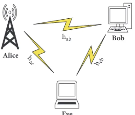
In this work, we consider a Single Input Single Output (SISO) OFDM-IM system. The basic system model consists of a legitimate transmitter (Tx), Alice, that wants to communicate securely with a legitimate receiver (Rx), Bob, in the presence of an illegitimate node, Eve, as shown in Figure 1, where TDD is considered as an operational mode. The notations
h𝑎𝑏(h𝑏)∈[1×𝐿]and h𝑎𝑒(h𝑒)∈[1×𝐿]denote the slow varying mul-tipath Rayleigh fading exponentially decaying channel from
Alice to Bob and Alice to Eve, respectively, where𝐿 is the
length of the channel. In this work, Eve is considered to be passive, and hence there is no knowledge of Eve’s channel at Alice. Moreover, it is also assumed that Eve is not very
Alice Eve Bob B;< B;? B?<
Figure 1: System model.
close to Bob such that Bob and Eve will have independent channel realizations [20]. In addition, the property of channel reciprocity is also adopted in this work, where the channel
from Alice to Bob (h𝑎𝑏) can be estimated from the channel of
Bob to Alice (h𝑏𝑎) in TDD.
3. Adaptive OFDM-IM Model and Proposed
Algorithms
In this Section, basic concepts related to OFDM-IM with respect to adaptivity as well as proposed algorithms for enhancing PLS and SE are presented.
3.1. Adaptive IM Model. In this subsection,
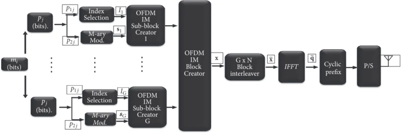
OFDM-IM model [5, 6] with respect to channel based adaptation (CBA) is explained. In this system, we employ a simplified OFDM-IM model as presented in Figures 2 and 3, where Figure 2 presents the OFDM-IM transmitter (Tx) while Figure 3 presents the OFDM-IM receiver (Rx),
respec-tively. Let us suppose that𝑚𝑖 number of information bits,
corresponding to 𝑖𝑡ℎ block, enters the OFDM-IM for the
transmission, where the value of𝑚𝑖is different for different
OFDM-IM blocks due to CBA and will be explained in
Section 3.2. These𝑚𝑖bits are split into𝐺 groups, such that
each group contains 𝑝𝑗 bits, where 𝑗 ∈ {1, . . . , 𝐺}. The
𝑝𝑗 may be different for different groups based on CBA.
The total number of bits in𝑖𝑡ℎ block can be represented as
follows:
𝑚𝑖=∑𝐺
𝑗=1
𝑝𝑗 (1)
In OFDM-IM, the subcarriers are also divided into 𝐺
subblocks. The number of subcarriers in any subblock,𝛽, is
𝑛, where 𝑛 = 𝑁/𝐺 and 𝑁 is the total number of subcarriers
in any OFDM-IM block. After that,𝑝𝑗bits of each group are
mapped to corresponding subblock,𝛽. This mapping is done
by means of symbols and by the indices of subcarriers based on CBA.
The𝑝𝑗bits of each group are divided into𝑝1𝑗and𝑝2𝑗bits,
where𝑝1𝑗bits are carried by indices and𝑝2𝑗bits are carried
by symbols. More specifically, in each OFDM subblock,
𝑘𝑗 out of 𝑛 subcarriers are active and selected by index
Table 1: Lookup table for SAR values of{1/4, 2/4, 3/4}.
(a) SAR: [1/4]
Bits Subcarrier indices
00 1
01 2
10 3
11 4
(b) SAR: [2/4]
Bits Subcarrier indices
00 1, 2
01 2, 3
10 3, 4
11 1, 4
(c) SAR: [3/4]
Bits Subcarrier indices
00 1, 2, 3
01 1, 2, 4
10 1, 3, 4
11 2, 3, 4
selector based on𝑝1𝑗bits while the symbols corresponding
to inactive subcarriers are set to zero. In the proposed work, each subblock may have different Subcarrier Activation Ratio
(SAR),𝑘𝑗/𝑛, and Constellation Modulation (CM) order based
on CBA. In this work, we consider four cases for SAR that are 1/4, 2/4, 3/4, and 4/4 and four cases of CM that are 2, 4, 8,
and16. The index selector of OFDM-IM uses a predefined
lookup table for each subblock based on its SAR. Table 1
presents lookup tables for SARs of1/4, 2/4, and 3/4, while
the case of SAR value of 4/4 does not require any lookup
table because no information is sent by indices (Classical
OFDM). The remaining𝑝2𝑗bits are mapped on to M-ary data
symbols, based on subblock CM, that modulates the active subcarriers. In this way, the information is conveyed by both indices of subcarriers and M-ary symbols that modulate the active subcarriers.
The selected indices are given by 𝐼𝛽 = {𝑖𝛽,1, . . . , 𝑖𝛽,𝑘𝑗},
where𝛽 ∈ {1, . . . , 𝐺}, 𝑖𝛽,𝛾 ∈ {1, . . . , 𝑛}, and 𝛾 ∈ {1, . . . , 𝑘𝑗}.
Therefore, the total number of bits carried by the indices of
all𝐺 groups in the 𝑖𝑡ℎblock is given by
𝑚1𝑖=∑𝐺
𝑗=1
𝑝1𝑗, (2)
𝑝1𝑗= ⌊log2(𝑛
OFDM IM Sub-block Creator 1 OFDM IM Sub-block Creator G OFDM IM Block Creator G x N Block interleaver Cyclic prefix IFFT Index Selection M-ary Mod. M-ary Mod. (bits) (bits). (bits). Index Selection P/S x mi pj pj p1j p2j p1j p2j I1 s1 IG G x q
Figure 2: Basic OFDM-IM Tx.
ML/LLR Detector Receiver Signal Separation G x N Block Deinterleaver Cyclic prefix Removal (bits). yd y u yfd yfd(1) yfd(N) mi FFT
Figure 3: Basic OFDM-IM Rx.
Hence,𝐼𝛽has𝑐 = 2𝑝1𝑗possible realizations. On the other
hand, the total number of information bits carried by M-ary signal constellations is given by
𝑚2𝑖=∑𝐺
𝑗=1
𝑝2𝑗, (4)
𝑝2𝑗= 𝑘𝑗log2𝑀𝑗, (5)
where𝑀𝑗 is the modulation order and𝑘𝑗is the number of
active subcarriers in each subblock. In this scheme, the total number of active subcarriers in each OFDM block is given as
𝐾 = ∑𝐺𝑗=1𝑘𝑗. The output of M-ary modulator is given as
s𝛽= [𝑠𝛽(1) , . . . , 𝑠𝛽(𝑘𝑗)] , (6)
where 𝑠𝛽(𝛾) ∈ S. It should also be noted that the signal
constellation is normalized to have unit average power.
Finally, the OFDM block creator uses𝐼𝛽and s𝛽to create all
of subblocks and then forms𝑁 × 1 main OFDM-IM block by
concatenation of𝐺 subblocks and is given by
x= [𝑥1, 𝑥2, . . . , 𝑥𝑁]𝑇. (7)
where𝑥(𝛼) ∈ {0, S}, 𝛼 ∈ {1, . . . , 𝑁}. After this point, the
block x is passed through𝐺 × 𝑁 interleaver to ensure that
the subcarriers in each subblocks are affected by uncorrelated wireless fading channels.
The resultant OFDM block after interleaver, ̃x, is then
passed through IFFT process,(𝑁/√𝐾)𝐼𝐹𝐹𝑇{̃x}, which maps
the frequency domain data symbols to time domain points represented as follows:
̃q = [𝑞1, 𝑞2, . . . , 𝑞𝑁]𝑇 (8)
In order to avoid ISI, a CP of length (𝐿𝑐𝑝) is added at the
beginning of each block, where𝐿𝑐𝑝is assumed to be equal to
or greater than the channel delay spread. Finally, the resultant
signal ̃q ∈ 𝐶[𝑁+𝐿×1] is transmitted through the Rayleigh
fading channel, which is assumed to be constant during the transmission of each OFDM block and reaches both Bob and Eve. The baseband signal received at Bob can be represented as
y𝑏= h𝑏∗ ̃q + z𝑏, (9)
where h𝑏 is the channel impulse response seen by Bob and
z𝑏represents additive white Gaussian noise (AWGN) at Bob
with distribution of CN(0, 𝑁0,𝑇). Similarly, the baseband
signal received at Eve is given by
y𝑒= h𝑒∗ ̃q + z𝑒, (10)
where h𝑒is the channel impulse response seen by Eve and z𝑒
represents AWGN at Eve with distribution ofCN(0, 𝑁0,𝑇𝐸).
The basic block diagram of the receiver is presented in Figure 3. The receiver (both Bob and Eve) first removes the CP and then applies FFT on the received time domain
signal y𝑑 with normalization factor of 𝐾/√𝑁 and finally
deinterleaves the resultant signal to get the received signal,
y𝑓𝑑 = [𝑦𝑓𝑑(1), 𝑦𝑓𝑑(2), . . . , 𝑦𝑓𝑑(𝑁)]𝑇, in frequency domain,
where𝑑 can be Bob or Eve.
The receiver task is to detect the indices of active
sub-carriers and corresponding symbols by processing,𝑦𝑓𝑑(𝛼),
where 𝛼 = {1, . . . , 𝑁}. In our algorithm, we use lookup
table based modified Log-likelihood-Ratio (LLR) detector for detection of active indices for each subblock [6]. First of all, LLR values of frequency domain symbols corresponding to each subcarrier are calculated as follows:
𝜆 (𝛼) = ln (∑
𝑀
𝜒=1𝑃 (𝑥 (𝛼) = 𝑠𝜒 | 𝑦𝑓𝑑(𝛼))
𝑃 (𝑥 (𝛼) = 0 | 𝑦𝑓𝑑(𝛼))
The above equation can be further simplified by using Bayes’ formula as 𝜆 (𝛼) = ln (𝑘) − ln (𝑛 − 𝑘) +𝑦𝑓𝑑(𝛼) 2 𝑁0,𝑓 + ln (∑𝑀 𝜒=1 exp(− 1 𝑁0,𝑓𝑦𝑓𝑑(𝛼) − ℎ𝐹(𝛼) 𝑠𝜒 2 )) (12)
where𝑁0,𝑓is the noise variance in frequency domain (𝑁0,𝑓=
(𝐾/𝑁)𝑁0,𝑇). In (12), numerical overflow can be prevented by
using the Jacobian logarithm [27]. For example, for𝑀 = 2
and𝑘𝑗 = 𝑛/2, (12) simplifies to 𝜆 (𝛼) = max (𝑎, 𝑏) + ln (1 + exp (− |𝑏 − 𝑎|)) +𝑦𝑓𝑑(𝛼) 2 𝑁0,𝑓 (13) where 𝑏 = −|𝑦𝑓𝑑(𝛼) + ℎ𝑓(𝛼)|2/𝑁0,𝑓 and 𝑎 = −|𝑦𝑓𝑑(𝛼) − ℎ𝑓(𝛼)|2/𝑁
0,𝑓. In our work, we also use higher order
mod-ulation and use the following identity: ln(𝑒𝑎1 + 𝑒𝑎1 +
⋅ ⋅ ⋅ + 𝑒𝑎𝑀) = (𝑓
𝑚𝑎𝑥(𝑓𝑚𝑎𝑥(. . . 𝑓𝑚𝑎𝑥(𝑓𝑚𝑎𝑥(𝑎1, 𝑎2), 𝑎3), . . .), 𝑎𝑀)),
where𝑓𝑚𝑎𝑥(𝑎, 𝑏) = ln(𝑒𝑎1+𝑒𝑎1) = 𝑚𝑎𝑥(𝑎
1, 𝑎2)+ln(1+𝑒−|𝑎1−𝑎2|).
In order to detect the active indices, LLR value corre-sponding to each subcarrier is calculated using (12). After-wards, the receiver calculates the sum of LLRs corresponding to each combination of the subcarriers in the lookup table with respect to subblock based SAR as follows:
𝑑𝑤𝛽 =
𝑘𝑗
∑
𝛾=1
𝜆 (𝑛 (𝛽 − 1) + 𝑖𝑤𝛽,𝛾) (14)
where𝑤 = 1, . . . , 𝑐 and 𝑐 is the total number of combinations
of subcarriers in the lookup table with respect to any SAR. The receiver makes a decision of set of active indices by selecting the set with maximum value of sum of LLRs as follows:
̂
𝑤 = arg max𝑤 𝑑𝑤𝛽 (15)
After selecting the set with maximum LLR, the receiver gets the set of active indices corresponding to SAR. After the detection of active subcarrier, the information is then passed
to index demapper based on lookup table to estimate𝑚1𝑖bits.
After determination of active indices, the demodulation of the constellation symbols (M-ary symbols) is carried out and
finally we get𝑚2𝑖bits.
3.2. Proposed Algorithms for OFDM-IM. In this subsection,
proposed algorithms for enhancing PLS and spectral effi-ciency are presented.
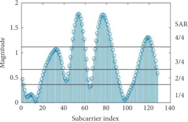
3.2.1. OFDM-AIM-FCM. In OFDM-AIM-FCM, SAR for
each subblock is changed adaptively while fixed CM is used for all subblocks. The basic idea of OFDM-AIM-FCM is presented in Figure 4. The basic steps for OFDM-AIM-FCM algorithm are as follows:
M agni tude 2 1.5 1 0.5 0 Subcarrier index 0 20 40 60 80 100 120 140 SAR 4/4 3/4 1/4 2/4
Figure 4: Proposed: OFDM-IM-AIM-FCM.
(i) In the first step, the channel is estimated at all nodes. In order to do that, Alice and Bob send a reference signal to each other (within coherence time). After channel estimation, they take FFT to convert the channel coefficient vector into frequency domain
vector, h𝑓
(ii) Afterwards, the vector h𝑓at each node is divided into
𝐺 subblocks with 𝑛 elements in each of, 𝛽, subblock,
where𝑛 = 𝑁/𝐺
(iii) In the next step, the average,𝑎V(𝛽), of absolute values
of subblock’s elements is calculated as follows:
𝑎V (𝛽) = ∑
𝑛 𝑟=1ℎ𝑠𝛽,𝑟
𝑛 , (16)
whereℎ𝑠𝛽,𝑟is the𝑟𝑡ℎelement of𝛽 subblock
(iv) After finding the average value,𝑎V(𝛽), for each of 𝐺
subblocks, they are divided into four groups based
on their𝑎V(𝛽). More specifically, find the mean, 𝑚𝑒,
of ak, where ak is a vector containing average values for all subblocks. Afterwards, divide the subblocks
into two groups, g1 and g2, by comparing their
corresponding𝑎V(𝛽) values with 𝑚𝑒. The subgroup
g1 contains those subblocks whose𝑎V(𝛽) values are
greater than or equal to𝑚𝑒 while g2 contains those
subblocks whose values of 𝑎V(𝛽) are less than 𝑚𝑒.
Afterwards, both g1and g2 are further divided into
two subgroups by using mean method as explained
above. As a result,𝐺 subblocks are divided into four
groups such as g11, g22, g33, and g44. The resultant
groups are sorted in descending order in terms of
average channel magnitude such that g11 contains
those subblocks that have the highest values of𝑎V(𝛽)
while g44contains subblocks with the lowest values of
𝑎V(𝛽)
(v) Finally, higher SAR values are selected for those
groups that have higher values of𝑎V(𝛽) while lower
values of SAR are selected for those groups that have
lower values of𝑎V(𝛽), such that SAR values of 4/4,
3/4, 2/4, and 1/4 are selected for groups g11, g22, g33,
Table 2: OFDM-AIM-FCM. 𝐺𝑟𝑜𝑢𝑝 SAR g11 4/4 g22 3/4 g33 2/4 g44 1/4 M agni tude 2 1.5 1 0.5 0 Subcarrier index 0 20 40 60 80 100 120 140 SAR 4/4 3/4 1/4 2/4 CM 16 8 4 2
Figure 5: Proposed: OFDM-AIM-ACM.
Based on the above algorithm (OFDM-AIM-FCM), Alice determines SAR for each subblock and the total number
of bits, 𝑚𝑖, for 𝑖𝑡ℎ block. Afterwards, data is loaded to the
indices and the symbols based on adaptive SAR and fixed CM and a block is generated using adaptive OFDM-IM model
explained in Section 3.1. Finally, the resultant signal ̃q ∈
𝐶[𝑁+𝐿×1]is transmitted through the Rayleigh fading channel
and reaches both Bob and Eve.
Bob and Eve will then detect the active subcarriers based on SAR values of subblocks with respect to OFDM-AIM-FCM. The resultant information is passed to the index demapper that provides the information carried by indices. After determination of active indices, constellation symbols are demodulated.
Thanks to channel decorrelation assumptions, Bob and Eve will have differences in their determined subblock based SAR values. Due to channel reciprocity employment, the SAR values for different subblocks determined by Bob are similar to that of Alice’s while they are different at Eve. This dissimilarity in SAR values for different subblocks at Eve leads to wrong detection of bits at Eve. Hence, there is a performance gap at Bob and Eve, which enables the secure communication between Alice and Bob.
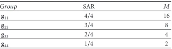
3.2.2. OFDM-AIM-ACM. In OFDM-AIM-ACM both the
SAR and CM order are adaptively varied based on channel of legitimate node in order to enhance PLS and SE. The basic concept of OFDM-AIM-ACM is presented in Figure 5.
(i) First four steps of OFDM-AIM-ACM are similar to
that of OFDM-AIM-FCM. Specifically, h𝑓 vector is
divided into𝐺 subblocks. The resultant 𝐺 subblocks
are grouped into four groups such as g11, g22, g33, and
g44using mean method as explained earlier
Table 3: OFDM-AIM-ACM. 𝐺𝑟𝑜𝑢𝑝 SAR 𝑀 g11 4/4 16 g22 3/4 8 g33 2/4 4 g44 1/4 2
(ii) The basic difference in OFDM-AIM-ACM as com-pared to OFDM-AIM-FCM is that both the SAR and CM order are varied adaptively for each subblock in it. In OFDM-AIM-ACM, higher SAR with higher order CM are selected for those groups that have high values
of𝑎V(𝛽) while lower values of SAR with lower order
CM are selected for those groups that have lower
values of𝑎V(𝛽). Based on OFDM-AIM-ACM, SAR
value of4/4 is selected with 𝑀 = 16, 3/4 with 8, 2/4
with4, and 1/4 with 2 for groups g11, g22, g33, and g44,
respectively, as presented in Table 3
Based on the above-mentioned algorithm (OFDM-AIM-ACM), Alice determines SAR and CM order for each
subblock and the total number of bits, 𝑚𝑖, for 𝑖𝑡ℎ block.
Afterwards, data is loaded to the indices and symbols based on adaptive SAR and adaptive CM and finally a block is generated using adaptive OFDM-IM model explained in
Section 3.1. Finally, the resultant signal ̃q ∈ 𝐶[𝑁+𝐿×1] is
transmitted through the Rayleigh fading channel and reaches both Bob and Eve.
Bob and Eve will first detect active subcarriers based on subblock-SAR values with respect to OFDM-AIM-ACM. The resultant information is then passed to the index demapper which provides the information carried by indices. After determination of active indices, constellation symbols are demodulated based on subblock CM order with respect to OFDM-AIM-ACM.
Due to the channel decorrelation, the SAR values and CM orders of different subblocks determined by Bob and Eve based on OFDM-AIM-ACM are different. The SAR values and CM orders of different subblock determined by Bob are similar to that of Alice’s due to channel reciprocity, while it is different at Eve as compared to Alice. This difference in subblock based SAR values as well as CM order at Eve compared to Alice will cause errors in the detection of data carried by indices and symbols. Hence, there is a significant performance gap between Bob and Eve. This performance gap will ensure secure communication between Alice and Bob. It should also be noted that OFDM-AIM-ACM is more difficult to be attacked as compared to OFDM-AIM-FCM because in the latter case only subblock based SAR is varied adaptively, while in the former both the SAR and CM are varied adaptively.
3.2.3. OFDM-VIM-VCM for QoS. In OFDM-VIM-VCM, the
IM and CM order are varied for QoS based communication in order to maximize the spectral efficiency. The basic moti-vation behind this approach is that, instead of using complex
optimization based approaches for maximizing spectral effi-ciency, simple simulation based approach is proposed for this purpose. The basic concept is to vary the SAR and CM with the change in average SNR to maximize the spectral efficiency while fulfilling certain QoS requirement. The basic procedure can be summarized as follows:
(i) First, OFDM-IM is implemented with different mod-ulation order for each SAR. Afterwards, BER and throughput curves are simulated for each of SAR value with higher order modulation; for example, in
this work, we are considering SAR values of1/4, 2/4,
3/4, and 4/4 and CM order of 2, 4, 8, and 16
(ii) Then, all BER curves are merged in one figure and all throughput curves in another figure
(iii) In the next step, certain BER curves are selected based on their performance gap and throughput values. More specifically, among the BER curves that have similar performance, select a curve that has maximum value of throughput. From the selected curves in the former step, select those curves that have a performance gap between them. Afterwards, the throughput curves corresponding to selected BER curves are also selected
(iv) Finally, switching table is constructed based on QoS requirement. The table depicts the values of different SAR and CM of system for different average SNR ranges to maximize the spectral efficiency while fulfilling QoS requirements
(v) After construction of switching table, this table is then used for QoS based communication for maximizing spectral efficiency
4. Performance Analysis of Adaptive
OFDM-IM Scheme
4.1. Throughput of Adaptive OFDM-IM. This section presents
the details related to the throughput of the adaptive OFDM-IM. The throughput for adaptive OFDM-IM can be given as
𝑇ℎ𝑟𝑜𝑢𝑔ℎ𝑝𝑢𝑡 = ∑
𝐺
𝑗=1𝑝1𝑗+ ∑𝐺𝑗=1𝑝2𝑗
𝑁 + 𝑁𝐶𝑃 (17)
where 𝑝1𝑗 = ⌊log2(𝑘𝑛𝑗)⌋ and 𝑝2𝑗 = 𝑘𝑗log2𝑀𝑗. The basic
difference between conventional OFDM-IM and adaptive
OFDM-IM is in 𝑘𝑗 and 𝑀𝑗 which are fixed in the former
but vary adaptively in the latter. In case of
OFDM-ACM-FCM,𝑘𝑗 is different for different subblocks and 𝑀𝑗 is the
same for all subblocks while in case of OFDM-ACM-AIM and
OFDM-VIM-VCM both𝑘𝑗and𝑀𝑗are different for different
subblocks.
4.2. Performance Analysis of Adaptive OFDM-IM Scheme.
This section presents the analytical evaluation for the upper bound of the average bit error probability (ABEP) of the
adaptive OFDM-IM scheme (OFDM-AIM-FCM with𝑀 =
2) based on pairwise error probability (PEP). In this analysis,
ML detector with a lookup table is considered whose results are equal to and applicable to the modified LLR detector (near ML) with a lookup table. This is because of the fact that the error performance of ML detector is almost similar to that of modified LLR detector as explained in [6].
In the conventional OFDM-IM, the same SAR values are used in all subblocks while in case of OFDM-AIM-FCM different SARs values are used in different subblocks. As
explained earlier, there are𝑁 subcarriers that are divided into
𝐺 subblocks with 𝑛 subcarriers in each subblock. In
OFDM-AIM-FCM, the subblocks are divided into four groups, g44,
g33, g22, and g11, with SAR values of1/4, 2/4, 3/4, and 4/4,
respectively, used in them. In order to simplify the analysis, we can assume that the size of each of the above-mentioned groups in OFDM-AIM-FCM is the same. It should be noted that the PEP event is similar in the subblocks corresponding to the same group and is different for subblocks that belong to different groups.
In the first step, the average bit error probability (ABEP) of first subblock of first group is calculated and then the results are extended to include subblocks of other groups. Afterwards, we will find average ABEP for each group and finally find the ABEP of adaptive OFDM-IM subblock.
The input-output relationship in frequency domain for the first subblock of first group is given as follows:
y= Xh + w. (18)
where X is an 𝑛 × 𝑛 diagonal matrix containing
[𝑥(1), 𝑥(2), . . . , 𝑥(𝑛)]𝑇 as diagonal data elements,
y is the received signal subvector containing
[𝑦𝑓𝑑(1), 𝑦𝑓𝑑(2), . . . , 𝑦𝑓𝑑(𝑛)]𝑇, h is the channel subvector
containing [ℎ𝑓(1), ℎ𝑓(2), . . . , ℎ𝑓(𝑛)]𝑇, and w is the noise
subvector containing[𝑤(1), 𝑤(2), . . . , 𝑤(𝑛)]𝑇. Let us assume
that Kn = 𝐸[hh𝐻] is a covariance submatrix of rank 𝑟1
(𝑟1 = rank(Kn)). This matrix is valid for all subblocks.
Moreover, the concatenation of these small covariance submatrices gives K matrix which is the covariance matrix of
h𝑓.
Let us suppose that X signal is transmitted through
channel and received as erroneous signal ̂X. The receiver
can make decision error in both constellation symbols and indices. One of the best ways to analyse these errors is in terms of PEP. In [28], an expression for conditional pairwise error probability (CPEP) is presented for the model of (18) and is given as
𝑃 (X → ̂X| h) = 𝑄 (√ 𝛿
2𝑁0,𝑓) , (19)
where𝛿 = hHAhand the A matrix equals to(X−̂X)𝐻(X−̂X).
In order to find the unconditional pairwise error probability (UPEP), the expectation of CPEP is taken with respect to the
channel and is given as follows:𝑃(X → ̂X) = 𝐸ℎ{𝑄(𝑥)}.
Based on [29], we can define an orthogonal matrix F where
FHF = I. The covariance submatrix and channel can be
simplified as Kn = FDFH and h = Fu, respectively. Here,
is eigen vector. Using the probability density function (p.d.f.)
of u [6] and simplification of𝑄(𝑥) and 𝛿, the unconditional
pairwise error probability (UPEP) can be written as
𝑃 (X → ̂X) = 1/12
det(In+ 𝑞1B)+
1/4
det(In+ 𝑞2B), (20)
where Inis an identity matrix, B= AKn,𝑞1= 1/(4𝑁0,𝑓), and
𝑞2= 1/(3𝑁0,𝑓). The above equation can be further simplified
as follows: 𝑃 (X → ̂X) = (12𝑞1𝑟 𝑟 ∏ 𝜉=1 𝜆𝜉(𝐵)) −1 + (4𝑞𝑟 2 𝑟 ∏ 𝜉=1 𝜆𝜉(𝐵)) −1 (21)
where𝑟 ≤ min{𝑟1, 𝑟2} and 𝑟2= rank(𝐴). For different SAR, 𝑟2
will be different, so (21) is still applicable to any SAR.
The overall average bit error probability of𝜏𝑡ℎsubblock of
any group can be calculated by using UPEP as follows:
𝑃𝑏𝜏(𝐸) ≈ 𝑝𝜏1𝑛𝜏
𝑥∑X𝜏∑X̂𝜏
𝑃 (X𝜏→ ̂X𝜏) 𝑒 (X𝜏, ̂X𝜏) , (22)
where𝑝𝜏is the number of information bits in𝜏𝑡ℎsubblock of
any group,𝑛𝜏𝑥represents the number of realizations of X𝜏, and
𝑒(X𝜏, ̂X𝜏) is the number of information bit errors committed
by choosing ̂X𝜏instead of X𝜏. Using (22), the ABEP forΥ𝑡ℎ
group can be calculated as follows:
𝑃𝑏Υ(𝐸) ≈ 1ϝ(∑ϝ
𝜏=1𝑃 𝜏
𝑏(𝐸)) (23)
whereϝ is the number of subblocks in any group and ϝ = 8
in our case. Equation (23) can be rewritten as follows:
𝑃𝑏Υ(𝐸) ≈ 1 ϝ ϝ ∑ 𝜏=1 ( 1 𝑝𝜏𝑛𝜏 𝑥∑X𝜏∑̂ X𝜏 𝑃 (X𝜏→ ̂X𝜏) 𝑒 (X𝜏, ̂X𝜏)) (24)
Finally, ABEP for the OFDM-IM block can be calculated as follows:
𝑃𝑏(𝐸) ≈ Ω1 ∑Ω
Υ=1
𝑃𝑏Υ(𝐸) ≈ Ω1 (𝑃𝑏1+ 𝑃𝑏2+ 𝑃𝑏3+ 𝑃𝑏4) (25)
whereΩ is the number of groups and in this case Ω = 4. The
theoretical BER curve will be presented in Section 5.
5. Simulation Result
This section presents the simulation results to evaluate the effectiveness of the proposed algorithms, named as OFDM-AIM-FCM, OFDM-AIM-ACM, and OFDM-VIM-VCM by using bit error rate (BER) and throughput as performance metrics.
Table 4: System parameters.
Channel Multipath Rayleigh fading channel
Channel length 10
OFDM frame size (N) 128
Length of subblock 4
Detector Modified LLR based detector
In this work, we consider an OFDM-IM system with 𝑁 = 128 subcarriers and a CP of length 10. As explained
in Section 3.1, OFDM-IM block is divided into𝐺 = 𝑁/𝑛 =
128/4 = 32 subblocks, where 𝑛 = 4 is the number of subcar-riers in each subblock. The multipath Rayleigh fading channel is considered for both Bob and Eve with equal number of channel taps (𝐿 = 10). The basic simulation parameters are presented in Table 4. In this work, lookup table based special LLR detector is employed at receiver, as explained in Section 3.1, to determine the active indices and corresponding constellation symbols based on the proposed algorithms. Additionally, we also consider that Eve knows our security algorithms. For simplicity and without loss of generality, CP is not considered in the throughput calculation.
It should be noted that the proposed scheme is a type of scheme which does not cause much difference in the SNR between Bob and Eve, but still Eve cannot decode, while Bob can decode (this case is somehow similar to the case of interleaver or precoder based security techniques [20, 30]). In such cases, BER can be used as a metric to measure secrecy instead of secrecy capacity and secrecy outage probability as reported in [20, 30, 31]. Therefore, in this work, we use BER-based secrecy gap metric [20] to evaluate the secrecy. Furthermore, in this work we are targeting quality of service (QoS) based security [16, 32]. The basic idea behind QoS based security is to secure different services (voice, video, etc.) instead of focusing on providing perfect secrecy. More specifically, it should be noted that perfect secrecy is not always needed to provide a perfectly secure service. In reality, each service has different QoS requirements than the others, and if we ensure that Eve is operating below these requirements, then practical secrecy can be guaranteed. So, in this work we target to provide security for services such as voice and video and make sure that error rate at Eve is greater than minimum required error rate criteria to use that service [16]. For example, voice and video can be made secure at Bob by making sure that PER (corresponding to BER) at Bob is less than minimum required PER (corresponding to BER) in order to use that service while PER at Eve is made greater than minimum required PER. The minimum PER requirement for different services is presented in Table 5 [26]. Hence, although the throughput is nonzero, the proposed scheme can still provide QoS based security (it should be noted that PER can
be calculated from BER as follows:𝑃𝐸𝑅 = 1 − (1 − 𝐵𝐸𝑅)𝑛),
where𝑛 is the block size [33]).
In the first phase, OFDM-IM is simulated for different
SAR values, such as1/4, 2/4, 3/4, and 4/4 based on lookup
tables presented in Table 1 with FCM (M=2). Afterwards, we simulate OFDM-AIM-FCM for BPSK (𝑀 = 2) for PLS and
Table 5: QoS lookup table [26]. 𝑆𝑒𝑟V𝑖𝑐𝑒 𝑃𝐸𝑅 Voice 10−2 Video 10−3 Eb/N0 [dB] 0 10 20 30 40 BER 1/4 2/4 3/4 4/4 100 10−1 10−2 10−3 10−4 10−5 10−6
Figure 6: BER performance for OFDM-IM (𝑛 = 4, 𝑘 = {1, 2, 3, 4}).
also extend it for higher order modulation such as𝑀 = 4,
𝑀 = 8, and 𝑀 = 16. Then, OFDM-AIM-FCM is extended to OFDM-AIM-ACM for providing another stronger PLS technique. Finally, we implement OFDM-VIM-VCM for QoS based communication in order to maximize the spectral efficiency.
5.1. OFDM-AIM-FCM. Figure 6 presents the BER plots for
OFDM-IM with different SAR values, such as1/4, 2/4, 3/4,
and 4/4 for 𝑀 = 2. It should be noted from Figure 6
that the BER performance for lower values of SAR is better than the case of higher values of SAR; for example, the BER
performance of1/4 case is the best while BER performance
of4/4 is the worst. The reason for the better performance of
BER at lower SAR is due to the fact that in case of lower SAR there will be less noise in the frequency domain.
Figure 7 presents throughput for OFDM-IM with
dif-ferent SAR values for 𝑀 = 2. It should be noted that the
throughput for the system improves as the activation ratio
increases except for the case with SAR value of3/4 which
outperforms4/4 case. The reason is that each subblock carries
4 bits in case of SAR value of 4/4 while each block carries 5
bits in case of3/4.
Figure 8 presents a comparison of BER performances among the proposed OFDM-AIM-FCM scheme, the scheme presented in [24], and OFDM-IM (𝑛 = 4, 𝑘 = 2) (Ref. (Ref. means the reference scheme to which we compare our proposed algorithm)). It is observed from Figure 8 that the BER performances of OFDM-AIM-FCM and OFDM-IM [6]
Eb/N0 [dB] Thr o ug h p u t [b ps/h] 0.5 0.6 0.7 0.8 0.9 1 1.1 1.2 1.3 1/4 2/4 3/4 4/4 0 10 20 30 40
Figure 7: Throughput performance for OFDM-IM (𝑛 = 4, 𝑘 = {1, 2, 3, 4}). Eb/N0 [dB] 0 5 10 15 20 25 30 35 40 BER Bob-AIM-FCM OFDM-IM (2/4) Eve-AIM-FCM Theo.(Adapt.) SM [Bob] (Nt=4,M=2) SM [Eve] 100 10−1 10−2 10−3 10−4 10−5 10−6
Figure 8: BER performance for OFDM-AIM-FCM, Secure SM [24] and OFDM-IM (𝑛 = 4, 𝑘 = 2).
are similar for the case of Bob but the scheme presented in [24] has the worst performance as compared to others. It is also observed that the performance of Eve is the worst for all values of SNR for the proposed OFDM-AIM-FCM technique and the scheme presented in [24] while her performance is similar to that of Bob for the cases of OFDM-IM [6]. Hence, the proposed technique and the technique presented in [24] are secure as compared to OFDM-IM [6]. Figure 8 also presents the theoretical upper bound BER performance of OFDM-AIM-FCM based on (25). It should
Eb/N0 [dB] 0 5 10 15 20 25 30 35 40 Thr o ug h p u t [b ps/h] 0.5 0.6 0.7 0.8 0.9 1 OFDM-IM (2/4) Bob-AIM-FCM Eve-AIM-FCM SM [Bob] (Nt=4,M=2) SM [Eve]
Figure 9: Throughput performance for OFDM-AIM-FCM, Secure SM [24] and OFDM-IM (𝑛 = 4, 𝑘 = 2).
be noted that theoretical curve becomes tight at higher SNR with the simulation curve.
Figure 9 shows the comparison of throughput perfor-mances among the proposed OFDM-AIM-FCM scheme, the scheme presented in [24], and OFDM-IM (𝑛 = 4, 𝑘 = 2) [6]
with𝑀 = 2. It is observed that the throughput performances
of all of these schemes for Bob are approximately similar at higher values of SNR. At equivalent BER we can notice that the throughput of the proposed OFDM-AIM-FCM scheme outperforms the OFDM-IM (2/4) [6] at lower values of SNR. Moreover, the proposed scheme (OFDM-AIM-FCM) also outperforms in terms of throughput as compared to the scheme presented [24] at lower values of SNR. It is also observed that the throughput performance of Eve is the worst for the proposed OFDM-AIM-FCM technique and the scheme presented in [24] while her performance is similar to that of Bob for the case of OFDM-IM [6] scheme.
5.2. OFDM-AIM-ACM. Figure 10 presents the BER
perfor-mance of Bob and Eve for OFDM-AIM-FCM for𝑀 = 2,
𝑀 = 4, 𝑀 = 8, and 𝑀 = 16. It should be noted from the figure that as the modulation order increases the BER performance degrades. The performance of Eve for
OFDM-AIM-FCM is the worst for all cases of CM such as𝑀 = 2,
𝑀 = 4, 𝑀 = 8, and 𝑀 = 16. Figure 10 also presents the BER performance of Bob and Eve for the proposed OFDM-AIM-ACM. It is observed from Figure 10 that the BER performance of OFDM-AIM-AIM is approximately the same as the case of
OFDM-AIM-FCM for𝑀 = 8, while the BER performance
of Eve is the worst for all values of SNR. Hence, OFDM-AIM-ACM can provide secure communication between Alice and Bob. Figure 11 presents throughput performance of Bob
and Eve for OFDM-AIM-FCM with 𝑀 = 2, 𝑀 = 4,
Eb/N0 [dB] BER Bob-AIM-FCM M=16 Bob-AIM-FCM M=8 Bob-AIM-FCM M=4 Bob-AIM-FCM M=2 Eve-AIM-FCM Bob-AIM-ACM Eve-AIM-ACM 0 5 10 15 20 25 30 35 40 100 10−1 10−2 10−3 10−4 10−5 10−6
Figure 10: BER performance for AIM-FCM and OFDM-AIM-ACM. Eb/N0 [dB] Thr o ug h p u t [b ps/h] 0.5 1 1.5 2 2.5 3 Bob-AIM-FCM M=16 Bob-AIM-FCM M=8 Bob-AIM-FCM M=4 Bob-AIM-FCM M=2 Eve-AIM-FCM M=16 Eve-AIM-FCM M=8 Eve-AIM-FCM M=4 Eve--AIM-FCM M=2 Bob--AIM-ACM Eve--AIM-ACM 0 5 10 15 20 25 30 35 40
Figure 11: Throughput performance for OFDM-AIM-FCM and OFDM-AIM-ACM.
𝑀 = 8, and 𝑀 = 16. Similarly, Figure 11 also presents the throughput results of our proposed OFDM-AIM-ACM based PLS technique for Bob and Eve. It is clear from Figure 11 that the throughput of OFDM-AIM-ACM is approximately
similar to the case of OFDM-AIM-FCM with𝑀 = 8 while
Eb/N0 [dB] BER 2/4 M=16 2/4 M=8 2/4 M=4 2/4 M=2 Bob-AIM-ACM Eve-AIM-ACM Bob-OFDM-FIM-ACM (2/4) Eve-OFDM-FIM-ACM (2/4) 0 5 10 15 20 25 30 35 40 100 10−1 10−2 10−3 10−4 10−5 10−6
Figure 12: BER comparison of IM (𝑛 = 4, 𝑘 = 2), OFDM-AIM-ACM, and OFDM-FIM-ACM (𝑛 = 4, 𝑘 = 2).
Eb/N0 [dB] Thr o ug h p u t [b ps/h] 0.6 0.8 1 1.2 1.4 1.6 1.8 2 2.2 2.4 2.6 2/4 M=16 2/4 M=8 2/4 M=4 2/4 M=2 Bob--AIM-ACM Eve-AIM-ACM Bob-OFDM-FIM-ACM (2/4) Eve-OFDM-FIM-ACM (2/4) 0 5 10 15 20 25 30 35 40
Figure 13: Throughput comparison of OFDM-IM (𝑛 = 4, 𝑘 = 2), OFDM-AIM-ACM, and OFDM-FIM-ACM (𝑛 = 4, 𝑘 = 2).
Figure 12 presents a comparison of BER performances between the proposed OFDM-AIM-ACM scheme and OFDM-IM (𝑛 = 4, 𝑘 = 2) (Ref.) with CM order of {2, 4, 8, 16}. It is observed from Figure 12 that the BER performance of OFDM-AIM-ACM is similar to the case of OFDM-IM (𝑛 = 4, 𝑘 = 2) (Ref.) with 𝑀 = 8. At equivalent BER, it is also noticed that the throughput of the
proposed OFDM-AIM-ACM outperforms the OFDM-IM (𝑛 = 4, 𝑘 = 2) (Ref.) with 𝑀 = 8 at all values of SNR as presented in Figure 13. It is also observed from Figures 12 and 13 that the BER and throughput performances of Eve are the worst at all values of SNR for the proposed OFDM-AIM-ACM scheme while her BER and throughput performances are similar to that of Bob for the cases of OFDM-IM (𝑛 = 4, 𝑘 = 2) (Ref.). Hence, the proposed scheme can enhance security and spectral efficiency jointly.
Moreover, Figures 12 and 13, respectively, also compare the BER and throughput performances of the OFDM-AIM-ACM scheme with the OFDM-FIM-OFDM-AIM-ACM (𝑛 = 4, 𝑘 = 2) based on [34]. It is observed from the figures that at approximately equivalent BER the proposed OFDM-AIM-ACM outperforms OFDM-FIM-OFDM-AIM-ACM (𝑛 = 4, 𝑘 = 2) in terms of throughput. It is also observed from Figures 12 and 13 that OFDM-FIM-ACM (𝑛 = 4, 𝑘 = 2) can also provide security. Note that OFDM-AIM-ACM is more secure as compared to OFDM-AIM-FCM because in the case of OFDM-AIM-ACM both SAR and CM are varied adaptively while in case of OFDM-AIM-FCM only SAR is varied.
The below subsections present the effect of imperfect channel estimation and effect of channel correlation between Bob’s channel and Eve’s channel on the performances of OFDM-AIM-FCM and OFDM-AIM-ACM.
5.2.1. Security Algorithms under Imperfect Channel Estima-tion. In order to evaluate the robustness of the proposed
security algorithms against imperfect channel estimation, intentional error is added at both the transmitter and receiver
(Δh𝑇/𝑅) to the true channel (h𝑏) to obtain new erroneous
channels given by ̃h𝑏 = h𝑏+ Δh [20, 35]. The intentional
error (Δh) is modeled as an independent complex Gaussian
noise with zero mean and variance (𝜎2= 𝑚𝑠𝑒 × 10−𝑆𝑁𝑅𝑑𝐵/10),
where𝑚𝑠𝑒 is a variable related to mean square of estimator’s
quality. Figures 14 and 15, respectively, present the BER performances for OFDM-AIM-FCM and OFDM-AIM-ACM
under different estimation qualities with𝑚𝑠𝑒 = 0 (perfect
estimation), 𝑚𝑠𝑒 = 0.02, 𝑚𝑠𝑒 = 0.05, and 𝑚𝑠𝑒 =
0.1. It is shown that imperfect channel estimation leads to small degradation in the BER performance. However, this degradation can be overcome by increasing the length or power of the training sequence. Moreover, there are some interesting algorithms proposed in the literature that can minimize the channel estimation error, such as in [1]
5.2.2. Effect of Eve’s Channel Correlation with Bob’s Channel.
This subsection presents the effect of the correlation between the channel of legitimate receiver and Eve and evaluate the performance in terms of BER as a security metric. Firstly, the assumption of channel decorrelation requires that Bob and Eve be located at more than one-half wavelength away from Alice. This is a practical assumption in many realistic scenarios and is assumed in many prominent works in the lit-erature (such as [21, 23, 24]). We have performed additional new simulations to show the effect of the correlation between the channels of legitimate receiver and eavesdropper on the
Eb/N0 [dB] BER Bob-AIM-FCM (mse=0) mse=0.02 mse=0.05 mse=0.1 0 5 10 15 20 25 30 35 40 100 10−1 10−2 10−3 10−4 10−5 10−6
Figure 14: BER comparison of OFDM-AIM-FCM (𝑚𝑠𝑒 = 0, 0.02, 0.05, 0.1). Bob-AIM-ACM (mse=0) (mse=0.02) (mse=0.05) (mse=0.1) Eb/N0 [dB] BER 0 5 10 15 20 25 30 35 40 100 10−1 10−2 10−3 10−4 10−5
Figure 15: BER comparison of OFDM-AIM-ACM (𝑚𝑠𝑒 = 0, 0.02, 0.05, 0.1).
secrecy performance that is measured in terms of BER as a security metric as explained above.
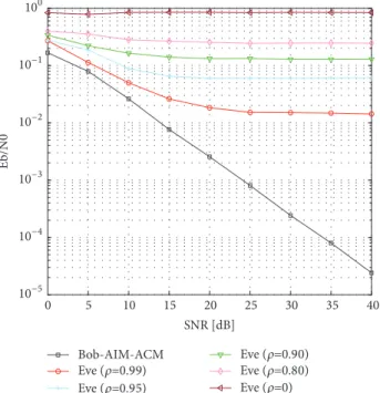
Figures 16 and 17, respectively, present the BER perfor-mances for OFDM-AIM-FCM and OFDM-AIM-ACM when Eve’s channel is correlated to Bob’s one. The model for channel correlation between the channels of legitimate receiver and
Eb/N0 [dB] BER Bob-AIM-FCM 0 5 10 15 20 25 30 35 40 100 10−1 10−2 10−3 10−4 10−5 10−6 Eve (=0.99) Eve (=0.95) Eve (=0.90) Eve (=0.80) Eve (=0)
Figure 16: BER comparison of Bob (OFDM-AIM-FCM) and Eve with correlation coefficient (𝜌 = 0, 0.80, 0.90, 0.95, 0.99).
SNR [dB] Eb/N0 Bob-AIM-ACM 0 5 10 15 20 25 30 35 40 100 10−1 10−2 10−3 10−4 10−5 Eve (=0.99) Eve (=0.95) Eve (=0.90) Eve (=0.80) Eve (=0)
Figure 17: BER comparison of Bob (OFDM-AIM-ACM) and Eve with correlation coefficient (𝜌 = 0, 0.80, 0.90, 0.95, 0.99).
eavesdropper assumed in this work is similar to the one presented in [24] and is given as follows:
h𝑒= 𝜌h𝑏+ (1 − 𝜌) E (26)
where 𝐸 represents an independent channel while 𝜌 is the
correlation factor. We present BER performance for the correlation values of (𝜌 = 0, 0.80, 0.90, 0.95, 0.99). It should be noted that even with correlation between Bob’s and Eve’s
Eb/N0 [dB] BER 1/4 M=2 1/4 M=4 1/4 M=8 1/4 M=16 100 10−1 10−2 10−3 10−4 10−5 10−6 0 5 10 15 20 25 30 35 40
(a) BER versus SNR (SAR=1/4)
Eb/N0 [dB] BER 2/4 M=2 2/4 M=4 2/4 M=8 2/4 M=16 100 10−1 10−2 10−3 10−4 10−5 10−6 0 10 20 30 40
(b) BER versus SNR (SAR=2/4)
Eb/N0 [dB] BER 3/4 M=2 3/4 M=4 3/4 M=8 3/4 M=16 100 10−1 10−2 10−3 10−4 10−5 10−6 0 5 10 15 20 25 30 35 40
(c) BER versus SNR (SAR=3/4)
Eb/N0 [dB] Thr o ug h p u t [b ps/h] 0.7 0.8 0.9 1 1.1 1.2 1.3 1.4 1.5 1.6 1/4 M=2 1/4 M=4 1/4 M=8 1/4 M=16 0 5 10 15 20 25 30 35 40
(d) Throughput versus SNR (SAR=1/4)
Eb/N0 [dB] Thr o ug h p u t [b ps/h] 0.8 1 1.2 1.4 1.6 1.8 2 2.2 2.4 2.6 2/4 M=2 2/4 M=4 2/4 M=8 2/4 M=16 0 5 10 15 20 25 30 35 40
(e) Throughput versus SNR (SAR=2/4).
Eb/N0 [dB] Thr o ug h p u t [b ps/h] 1 1.5 2 2.5 3 3.5 3/4 M=2 3/4 M=4 3/4 M=8 3/4 M=16 0 5 10 15 20 25 30 35 40
(f) Throughput versus SNR (SAR=3/4).
Figure 18: OFDM-IM with SAR values of (1/4, 2/4, 3/4) and CM orders of (2, 4, 8, and 16).
channels, the proposed algorithms can still provide some level of QoS based security.
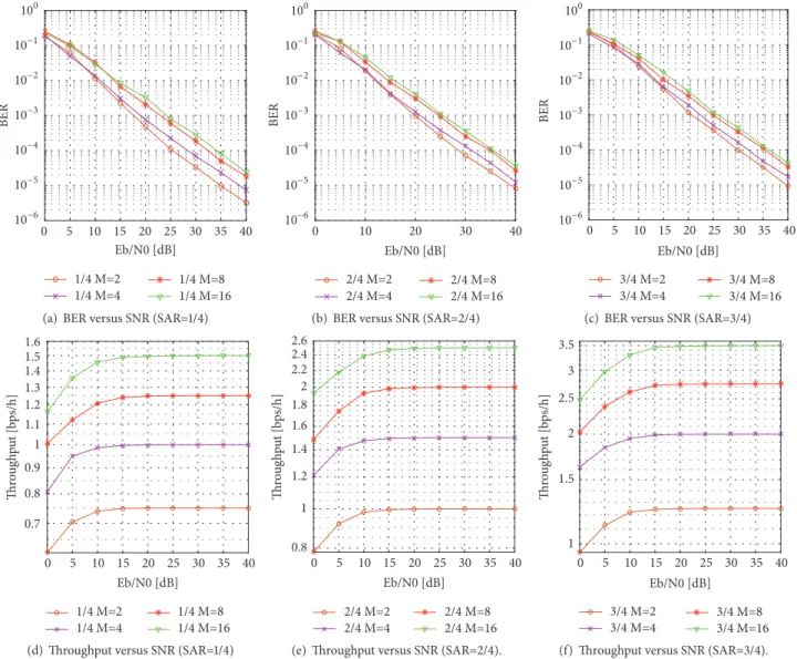
5.3. OFDM-VIM-VCM. Figures 18 and 19 present the
exten-sive simulations related to OFDM-VIM-VCM scheme for QoS based communication in order to maximize the spectral efficiency. Note that the system model for this technique is the same as explained in Section 2, except the Eve link, which is not considered in this case. The basic concept is to vary the SAR and CM with the increase in SNR to maximize the spectral efficiency while fulfilling certain QoS requirement. In this approach, BER and throughput curves for four types
of CM order, such as𝑀 = 2, 𝑀 = 4, 𝑀 = 8, and 𝑀 = 16, are
implemented for each of SAR types, such as1/4, 2/4, 3/4, and
4/4, and presented in Figures 18, 19(a), and 19(d). Afterwards, certain curves are selected based on OFDM-VIM-VCM for QoS based communication.
In Figure 19(b), we merge the BER curves of SAR values
of1/4, 2/4, 3/4, and 4/4 for CM order of 𝑀 = 2, 𝑀 = 4,
𝑀 = 8, and 𝑀 = 16. Similarly, in Figure 19(e), throughput
curves of SAR values of1/4, 2/4, 3/4, and 4/4 for CM order
of𝑀 = 2, 𝑀 = 4, 𝑀 = 8, and 𝑀 = 16 are also merged.
Afterwards, among the BER curves of Figure 19(b) that have similar performance, we select a curve that has maxi-mum value of throughput. From the selected curves in the former step, we select those curves that have a performance gap among them. Finally, the resultant curves are presented in Figure 19(c). Afterwards, the corresponding throughput curves of Figure 19(e) related to selected BER curves in Figure 19(c) are also selected and presented in Figure 19(f).
Based on Figures 19(c) and 19(f), we develop a switching tables for QoS based communication in order to maximize the throughput. In this work, as an example, switching among different modulation types based on the SNR for the case
of𝐵𝐸𝑅 < 10−3 and 𝐵𝐸𝑅 < 10−4 is presented in Table 6.
The table depicts different SAR and CM values of system for different SNR ranges to maximize the spectral efficiency while fulfilling different QoS requirements. Afterwards, this table can be used for different QoS based communication services for maximizing spectral efficiency in a similar way
Eb/N0 [dB] BER 4/4 M=2 4/4 M=4 4/4 M=8 4/4 M=16 0 10 20 30 40 100 10−1 10−2 10−3 10−4 10−5
(a) BER versus SNR (SAR=4/4)
Eb/N0 [dB] BER 1/4 M=2 2/4 M=2 3/4 M=2 4/4 M=2 1/4 M=4 2/4 M=4 3/4 M=4 4/4 M=4 1/4 M=8 2/4 M=8 3/4 M=8 4/4 M=8 1/4 M=16 2/4 M=16 3/4 M=16 4/4 M=16 100 10−1 10−2 10−3 10−4 10−5 10−6 0 10 20 30 40
(b) BER versus SNR (merged)
Eb/N0 [dB] BER 1/4 M=2 2/4 M=2 3/4 M=4 3/4 M=8 4/4 M=16 100 10−1 10−2 10−3 10−4 10−5 10−6 0 10 20 30 40
(c) BER versus SNR (selective)
Eb/N0 [dB] Thr o ug h p u t [b ps/h] 1 1.5 2 2.5 3 3.5 4 4/4 M=2 4/4 M=4 4/4 M=8 4/4 M=16 0 5 10 15 20 25 30 35 40
(d) Throughput versus SNR (SAR=4/4)
Eb/N0 [dB] Thr o ug h p u t [b ps/h] 1 1.5 2 2.5 3 3.5 4 4.55 1/4 M=2 2/4 M=2 3/4 M=2 4/4 M=2 1/4 M=4 2/4 M=4 3/4 M=4 4/4 M=4 1/4 M=8 2/4 M=8 3/4 M=8 4/4 M=8 1/4 M=16 2/4 M=16 3/4 M=16 4/4 M=16 0 10 20 30 40
(e) Throughput versus SNR (merged)
Eb/N0 [dB] Thr o ug h p u t [b ps/h] 1 1.5 2 2.5 3 3.5 4 4.55 1/4 M=2 2/4 M=2 3/4 M=4 3/4 M=8 4/4 M=16 OFDM-VIM-VCM 0 5 10 15 20 25 30 35 40 (BER<103)
(f) Throughput versus SNR (selective)
Figure 19: OFDM-IM with SAR value of (4/4) and CM orders of (2, M = 4, M = 8, and M = 16), merged curves for different cases of OFDM-IM and selected curves for different cases of OFDM-IM for QoS based communication.
as performed in [16]. The result of OFDM-VIM-VCM for the
case of𝐵𝐸𝑅 < 10−3is presented in Figure 19(f).
6. Conclusion
In this work, effective algorithms that change SAR and/or CM adaptively in each subblock of the OFDM-IM scheme based
on the channel characteristics of the legitimate receiver are proposed for enhancing PLS and SE. Particularly, the first two algorithms named as FCM and OFDM-AIM-ACM are designed for enhancing PLS and SE, while the third algorithm named as OFDM-VIM-VCM is designed for QoS based communication for enhancing SE. Simulation results show that the first two algorithms can provide significant security enhancement whereas the third algorithm ensures
Table 6: Switching table for OFDM-VIM-VCM.
(a) BER< 10−3
BER< 10−3
Eb/NO (E) M SAR
17.6<E<19.9 2 1/4 19.9<E<22.4 2 2/4 22.4<E<24.8 4 3/4 24.8<E<27.4 8 3/4 27.4<E 16 4/4 (b) BER< 10−4 BER< 10−4
Eb/NO (E) M SAR
25.3<E<28.6 2 1/4
28.6<E<32 2 2/4
32<E<35.3 4 3/4
35.3<E<37.3 8 3/4
37.3<E 16 4/4
QoS based communication aiming to maximize spectral efficiency.
Data Availability
The data used to support the findings of this study are included within the article.
Conflicts of Interest
The authors declare that there are no conflicts of interest regarding the publication of this paper.
References
[1] J. M. Hamamreh, H. M. Furqan, and H. Arslan, “Secure pre-coding and post-coding for OFDM systems along with hardware implementation,” in Proceedings of the 2017 13th
International Wireless Communications and Mobile Computing Conference (IWCMC), pp. 1338–1343, Valencia, Spain, June 2017.
[2] H. M. Furqan, J. M. Hamamreh, and H. Arslan, “Secret key generation using channel quantization with SVD for reciprocal MIMO channels,” in Proceedings of the 13th International
Sym-posium on Wireless Communication Systems, ISWCS 2016, pp.
597–602, Poland, September 2016.
[3] Y. Liu, H. H. Chen, and L. Wang, “Physical layer security for next generation wireless networks: Theories, technologies, and challenges,” in IEEE Communications Surveys Tutorials, vol. 19, no. 1, pp. 347–376, 2017.
[4] X. Chen, D. W. K. Ng, W. H. Gerstacker, and H. H. Chen, “A Survey on multiple-antenna techniques for physical layer security,”ΓΓ in IEEE Communications Surveys Tutorials, vol. 19, no. 2, pp. 1027–1053, 2017.
[5] E. Basar, M. Wen, R. Mesleh, M. Di Renzo, Y. Xiao, and H. Haas, “Index Modulation Techniques for Next-Generation Wireless Networks,” IEEE Access, vol. 5, pp. 16693–16746, 2017.
[6] E. g. Basar, U. Aygolu, E. Panayirci, and H. V. Poor, “Orthogonal frequency division multiplexing with index modulation,” IEEE
Transactions on Signal Processing, vol. 61, no. 22, pp. 5536–5549,
2013.
[7] J. Choi, “Coded OFDM-IM with Transmit Diversity,” IEEE
Transactions on Communications, vol. 65, no. 7, pp. 3164–3171,
2017.
[8] J. Li, M. Wen, X. Cheng, Y. Yan, S. Song, and M. H. Lee, “Gener-alized Precoding-Aided Quadrature Spatial Modulation,” IEEE
Transactions on Vehicular Technology, vol. 66, no. 2, pp. 1881–
1886, 2017.
[9] M. Wen, E. Basar, Q. Li, B. Zheng, and M. Zhang, “Multiple-Mode Orthogonal Frequency Division Multiplexing with Index Modulation,” IEEE Transactions on Communications, vol. 65, no. 9, pp. 3892–3906, 2017.
[10] E. Soujeri, G. Kaddoum, M. Au, and M. Herceg, “Frequency Index Modulation for Low Complexity Low Energy Commu-nication Networks,” IEEE Access, vol. 5, pp. 23276–23287, 2017. [11] M. Au, G. Kaddoum, S. Francois, and S. Ebrahim, “A Joint
Code-Frequency Index Modulation for Low-complexity, High Spectral and Energy Efficiency Communications,” https:// arxiv.org/abs/1712.07951.
[12] E. Soujeri, G. Kaddoum, and M. Herceg, “Design of an initial condition-index chaos shift keying modulation,” IEEE
Electron-ics Letters, vol. 54, no. 7, pp. 447–449, 2018.
[13] Q. Wang, H. Su, K. Ren, and K. Kim, “Fast and scalable secret key generation exploiting channel phase randomness in wireless networks,” in Proceedings of the IEEE INFOCOM, pp. 1422–1430, Shanghai, China, April 2011.
[14] H. Qin, Y. Sun, T.-H. Chang et al., “Power allocation and time-domain artificial noise design for wiretap OFDM with discrete inputs,” IEEE Transactions on Wireless Communications, vol. 12, no. 6, pp. 2717–2729, 2013.
[15] Z. E. Ankaral, M. Karabacak, and H. Arslan, “Cyclic Feature Concealing CP Selection for Physical Layer Security,” in
Pro-ceedings of the 2014 IEEE Military Communications Conference (MILCOM), pp. 485–489, Baltimore, MD, USA, October 2014.
[16] J. M. Hamamreh, M. Yusuf, T. Baykas, and H. Arslan, “Cross MAC/PHY layer security design using ARQ with MRC and adaptive modulation,” in Proceedings of the 2016 IEEE Wireless
Communications and Networking Conference, WCNC 2016,
Qatar, April 2016.
[17] E. Guvenkaya and H. Arslan, “Secure communication in frequency selective channels with fade-avoiding subchannel usage,” in Proceedings of the 2014 IEEE International Conference
on Communications Workshops, ICC 2014, pp. 813–818,
Aus-tralia, June 2014.
[18] D. W. Ng, E. S. Lo, and R. Schober, “Energy-Efficient Resource Allocation for Secure OFDMA Systems,” IEEE Transactions on
Vehicular Technology, vol. 61, no. 6, pp. 2572–2585, 2012.
[19] H. M. Furqan, J. M. Hamamreh, and H. Arslan, “Enhanc-ing physical layer security of OFDM systems us“Enhanc-ing channel shortening,” in Proceedings of the 2017 IEEE 28th Annual
International Symposium on Personal, Indoor, and Mobile Radio Communications (PIMRC), pp. 1–5, Montreal, QC, October
2017.
[20] J. M. Hamamreh, E. Basar, and H. Arslan, “OFDM-Subcarrier Index Selection for Enhancing Security and Reliability of 5G URLLC Services,” IEEE Access, 2017.
[21] F. Wu, R. Zhang, L.-L. Yang, and W. Wang, “Transmitter precoding-aided spatial modulation for secrecy communica-tions,” IEEE Transactions on Vehicular Technology, vol. 65, no. 1, pp. 467–471, 2016.
[22] L. Wang, S. Bashar, Y. Wei, and R. Li, “Secrecy Enhancement Analysis Against Unknown Eavesdropping in Spatial Modula-tion,” IEEE Communications Letters, vol. 19, no. 8, pp. 1351–1354, 2015.
[23] X. Wang, X. Wang, and L. Sun, “Spatial modulation aided physical layer security enhancement for fading wiretap chan-nels,” in Proceedings of the 2016 8th International Conference on
Wireless Communications & Signal Processing (WCSP), pp. 1–5,
Yangzhou, China, October 2016.
[24] X. Jiang, M. Wen, H. Hai, J. Li, and S. Kim, “Secrecy-Enhancing Scheme for Spatial Modulation,” IEEE Communications Letters, vol. 22, no. 3, pp. 550–553, 2018.
[25] Y. Lee, H. Jo, Y. Ko, and J. Choi, “Secure Index and Data Symbol Modulation for OFDM-IM,” IEEE Access, vol. 5, pp. 24959– 24974, 2017.
[26] “3GPP, Policy and charging control architecture, 3GPP Std. TS 23.203 V11.6.0,” 2012, http://www.qtc.jp/3GPP/Specs/23203-b60.pdf.
[27] P. Robertson, E. Villebrun, and P. Hoeher, “A comparison of optimal and sub-optimal MAP decoding algorithms operating in the log domain,” in Proceedings of the IEEE International
Conference on Communications (ICC ’95), vol. 2, pp. 1009–1013,
IEEE, Seattle, Wash, USA, June 1995.
[28] H. Jafarkhani, Space-Time Coding, Cambridge University Press, Cambridge, 2005.
[29] R. A. Horn and C. R. Johnson, Matrix Analysis, Cambridge University Press, Cambridge, UK, 1985.
[30] H. Li, X. Wang, and J.-Y. Chouinard, “Eavesdropping-resilient OFDM system using sorted subcarrier interleaving,” IEEE
Transactions on Wireless Communications, vol. 14, no. 2, pp.
1155–1165, 2015.
[31] E. G¨uvenkaya, J. M. Hamamreh, and H. Arslan, “On physical-layer concepts and metrics in secure signal transmission,”
Physical Communication, vol. 25, pp. 14–25, 2017.
[32] J. M. Hamamreh and H. Arslan, “Joint PHY/MAC Layer Security Design Using ARQ with MRC and Null-Space Inde-pendent, PAPR-Aware Artificial Noise in SISO Systems,” IEEE
Transactions on Wireless Communications, pp. 1-1.
[33] ICAO, “Uniting Aviation,” in Proceedings of the AN-Conf/13
- ICAO Thirteenth - Air Navigation Conference, Montereal,
Canada, Oct. 2018, https://www.icao.int.
[34] J. Faezah and K. Sabira, “Adaptive modulation for OFDM systems,” International Journal of Communication Networks and
Information Security, vol. 1, no. 2, pp. 1–8, 2009.
[35] J. M. Hamamreh and H. Arslan, “Secure Orthogonal Transform Division Multiplexing (OTDM) Waveform for 5G and beyond,”
International Journal of
Aerospace
Engineering
Hindawi www.hindawi.com Volume 2018Robotics
Journal of Hindawi www.hindawi.com Volume 2018 Hindawi www.hindawi.com Volume 2018 Active and Passive Electronic Components VLSI Design Hindawi www.hindawi.com Volume 2018 Hindawi www.hindawi.com Volume 2018 Shock and Vibration Hindawiwww.hindawi.com Volume 2018
Civil Engineering
Advances inAcoustics and VibrationAdvances in Hindawi
www.hindawi.com Volume 2018
Hindawi
www.hindawi.com Volume 2018
Electrical and Computer Engineering Journal of Advances in OptoElectronics Hindawi www.hindawi.com Volume 2018
Hindawi Publishing Corporation
http://www.hindawi.com Volume 2013 Hindawi www.hindawi.com
The Scientific
World Journal
Volume 2018 Control Science and Engineering Journal of Hindawi www.hindawi.com Volume 2018 Hindawi www.hindawi.com Journal ofEngineering
Volume 2018Sensors
Journal of Hindawi www.hindawi.com Volume 2018 Machinery Hindawi www.hindawi.com Volume 2018 Modelling & Simulation in Engineering Hindawi www.hindawi.com Volume 2018 Hindawi www.hindawi.com Volume 2018 Chemical EngineeringInternational Journal of Antennas and
Propagation International Journal of Hindawi www.hindawi.com Volume 2018 Hindawi www.hindawi.com Volume 2018 Navigation and Observation International Journal of Hindawi www.hindawi.com Volume 2018

![Table 5: QoS lookup table [26].](https://thumb-eu.123doks.com/thumbv2/9libnet/5423251.103215/9.900.474.810.107.435/table-qos-lookup-table-.webp)
![Figure 9 shows the comparison of throughput perfor- perfor-mances among the proposed OFDM-AIM-FCM scheme, the scheme presented in [24], and OFDM-IM (](https://thumb-eu.123doks.com/thumbv2/9libnet/5423251.103215/10.900.88.425.106.450/figure-comparison-throughput-perfor-perfor-mances-proposed-presented.webp)