Dual polarized broadband and all dielectric
partial cloaking using stacked graded index
structures
B. B. Oner,* M. G. Can, and H. Kurt
Nanophotonics Research Laboratory Department of Electrical and Electronics Engineering TOBB University of Economics and Technology, 06560 Ankara, Turkey
Abstract: We propose broadband one-dimensional optical cloaking design
based on isotropic and purely dielectric non-absorbent materials. The photonic structures are formed by utilizing graded index (GRIN) concept in stacked form. All simulations are performed by finite-difference time-domain and plane wave basis frequency time-domain numerical methods. Indications in ray optics are also presented for the cloaking device. The refractive index distribution of the design is also obtained via effective medium theory. The cloaking devices can reroute wavelengths of light in one dimension. The rerouted light is avoided to reach the interior region of the stacked GRIN structure. Unidirectional GRIN cloaking structure demonstrates low-loss and large bandwidth characteristics. It is shown that the structure operates in dual polarization mode. Performed numerical analyses reveal the capability of cloaking devices to hide arbitrary shaped large objects from the incident light.
©2014 Optical Society of America
OCIS codes: (230.3205) Invisibility cloaks; (230.5298) Photonic crystals; (230.7370) Waveguides; (110.2760) Gradient-index lenses.
References and links
1. M. Selvanayagam and G. V. Eleftheriades, “Experimental demonstration of active electromagnetic cloaking,” Phys. Rev. X 3(4), 041011 (2013).
2. N. Landy and D. R. Smith, “A full-parameter unidirectional metamaterial cloak for microwaves,” Nat. Mater. 12(1), 25–28 (2012).
3. D. Schurig, J. J. Mock, B. J. Justice, S. A. Cummer, J. B. Pendry, A. F. Starr, and D. R. Smith, “Metamaterial electromagnetic cloak at microwave frequencies,” Science 314(5801), 977–980 (2006).
4. J. B. Pendry, D. Schurig, and D. R. Smith, “Controlling electromagnetic fields,” Science 312(5781), 1780–1782 (2006).
5. W. Cai, U. K. Chettiar, A. V. Kildishev, and V. M. Shalaev, “Optical cloaking with metamaterials,” Nat. Photonics 1(4), 224–227 (2007).
6. J. Li and J. B. Pendry, “Hiding under the carpet: a new strategy for cloaking,” Phys. Rev. Lett. 101(20), 203901 (2008).
7. M. Gharghi, C. Gladden, T. Zentgraf, Y. Liu, X. Yin, J. Valentine, and X. Zhang, “A carpet cloak for visible light,” Nano Lett. 11(7), 2825–2828 (2011).
8. N. A. Mortensen, O. Sigmund, and O. Breinbjerg, “Prospects for poor-man's cloaking with low-contrast all-dielectric optical elements,” J. Eur. Opt. Soc. Rapid Publ. 4, 09008 (2009).
9. D. P. Gaillot, C. Croënne, and D. Lippens, “An all-dielectric route for terahertz cloaking,” Opt. Express 16(6), 3986–3992 (2008).
10. J. Valentine, J. Li, T. Zentgraf, G. Bartal, and X. Zhang, “An optical cloak made of dielectrics,” Nat. Mater. 8(7), 568–571 (2009).
11. L. H. Gabrielli, J. Cardenas, C. B. Poitras, and M. Lipson, “Silicon nanostructure cloak operating at optical frequencies,” Nat. Photonics 3(8), 461–463 (2009).
12. M. Yan, Z. C. Ruan, and M. Qiu, “Cylindrical invisibility cloak with simplified material parameters is inherently visible,” Phys. Rev. Lett. 99(23), 233901 (2007).
13. Z. C. Ruan, M. Yan, C. W. Neff, and M. Qiu, “Ideal cylindrical cloak: perfect but sensitive to tiny perturbations,” Phys. Rev. Lett. 99(11), 113903 (2007).
14. T. Ergin, N. Stenger, P. Brenner, J. B. Pendry, and M. Wegener, “Three-dimensional invisibility cloak at optical wavelengths,” Science 328(5976), 337–339 (2010).
15. A. E. Serebryannikov, P. V. Usik, and E. Ozbay, “Non-ideal cloaking based on Fabry-Perot resonances in single-layer high-index,” Opt. Express 17(19), 16869–16876 (2009).
16. A. E. Serebryannikov and E. Ozbay, “Non-ideal multifrequency cloaking using strongly dispersive materials,” Physica B 405(14), 2959–2963 (2010).
17. J. C. Howell, J. B. Howell, and J. S. Choi, “Amplitude-only, passive, broadband, optical spatial cloaking of very large objects,” Appl. Opt. 53(9), 1958–1963 (2014).
18. H. Chen, B. Zheng, L. Shen, H. Wang, X. Zhang, N. I. Zheludev, and B. Zhang, “Ray-optics cloaking devices for large objects in incoherent natural light,” Nat. Commun. 4, 3652 (2013).
19. R. K. Lüneburg, Mathematical Theory of Optics (University of California, 1964).
20. B. B. Oner, M. Turduev, and H. Kurt, “High-efficiency beam bending using graded photonic crystals,” Opt. Lett. 38(10), 1688–1690 (2013).
21. C. Gomez-Reino, M. V. Perez, and C. Bao, Gradient-Index Optics: Fundamentals and Applications (Springer, 2002).
22. A. Taflove and S. C. Hagness, Computational Electrodynamics: The Finite-Difference Time-Domain Method (Artech House Publisher, 2005).
23. A. F. Oskooi, D. Roundy, M. Ibanescu, P. Bermel, J. D. Joannopoulos, and S. G. Johnson, “MEEP: a flexible free software package for electromagnetic simulations by the FDTD method,” Comput. Phys. Commun. 181(3), 687–702 (2010).
1. Introduction
Making any object invisible to electromagnetic waves carries great potential. There have been various methods developed recently to implement cloaking idea [1–18]. The majority of them are based on metamaterials by using transformation optics and conformal mapping techniques [2–7]. While the approaches belong to wide disciplines, there are certain drawbacks that need to be handled. One of the problems is related to permittivity and permeability values of the designed media. Either, large range of variations is required or sometimes negative values have to be satisfied. In addition, required anisotropy of the device should be provided if some certain transformation methods are implemented. Another concern is related to the available bandwidth. If the designed device contains resonant elements, then the cloaking device properly operates only in a narrow bandwidth. We should also point out that metallic inclusions accompany loss problem. Finally, it is desirable to hide large size of object with an arbitrary shape. To circumvent all these disadvantages, some certain types of simplifications have been suggested. Implementing all dielectric materials is one type of solution to enable broadband and practically achievable designs [6–11]. An approach utilizing all dielectric material is called carpet cloaking [6,7]. This method enables a curved surface to response as a flat one. The arbitrary shaped hidden object is placed under this curved surface. However, this approach has some limitations during implementation such as sensitivity to lateral shift and angle dependency. Moreover, the operation is based on a reflection mode that requires the transmitter and receiver (observer) to be in the same side with respect to the target object. The idea pursued in the present work is similar to [8]. On the other hand, there are some distinctions between the two studies. The deployed medium in [8] has continuous index gradient and there was no proposal for implementing such a medium by artificial materials such as photonic crystals. Besides, polarization dependency and bandwidth concept are targeted in the current study. Lastly, we have flat front and back surfaces for the cloaking medium.
In the present work, we propose stacked graded index (GRIN) media [19] as cloaking devices where the refractive index distribution gradually varies along the transverse direction. This type of index variation leads light to bend within a broad frequency regime while metamaterials restrict the operating region to particular frequency values. GRIN media usually serve as multimode waveguides and flat lenses in optics. In addition to that, they are also used for many other applications. However, continuous and inhomogeneous index distribution may not be easily realized in practice. In order to overcome this issue, the proper arrangement of filling ratio of unit cells can be utilized to mimic certain index profiles [20]. Namely, photonic crystal (PC) structures enable to demonstrate unique features in photonics.
Purposely altering periodic distribution of unit cell will give rise to different inhomogeneous refractive index profiles. Therefore, we construct GRIN medium by using PCs. If only one host media and only one material type are utilized then two basic methods are available to generate the desired refractive indices. One of them is varying radii of PC to change the filling ratio and also the effective index. Another approach proposes keeping radii of the PCs constant while varying the unit cell dimensions. An additional advantage of the second technique provides only variation of the distances between the rods therefore it becomes the most feasible option. These implementations can be provided by analytical technique which is known as effective medium theory (EMT) or numerical approach which reveals dispersion diagram. Analytically, corresponding refractive indices for different polarizations, transverse- magnetic (TM) and electric (TE), can be found by the relations:
2 2 (1 ) forTMmodes, (1 ) (1 ) forTE modes, (1 ) (1 ) h r h r h h r n f f TM f f n TE f f ε ε ε ε ε ε ε = − + − + + = + + − (1)
where εh and εr are permittivity values of the host media and dielectric rods, respectively.
Besides the analytical approach, the relation between wave vectors (k) and the angular frequency (ω) is shown by dispersion diagram engineering. If any propagation is not allowed within a frequency range, this zone is called photonic band gap (PBG). The region below the PBG is the homogenization regime where EMT is also valid. Already, EMT and numerical method produce same index results for the first band at the long wavelength region. The reader easily sees from Eq. (1) that increasing f or choosing theεrat the proximity of
theεhleads the effective index to have an approximate value to the host medium refractive index. Thereby, choosing relatively low PC rod index enables both a broad band operation and low Fresnel reflection at around the interfaces between the cloaking medium and free-space. In Fig. 1, the effective indices of two PC rods with different unit cell sizes are given when εr =2.25andεh =1.00. When we calculate dispersion diagrams by plane wave expansion method for different cell sizes (only two different extreme cases for the cell size are plotted in Fig. 1) the dispersion bands have slightly different slopes. This feature produces effective index variation that can be tailored at will. Even though the relative permittivity and permeability values for the selected material are constant, unit cell size changes (smaller at the center and decreases at the outer region). As a result, filling factor gradually decreases in the transverse to propagation direction. That yields desired index gradient along the y-direction.
2. Methodology
As shown in Fig. 1, the corresponding effective indices in the first band have almost constant values for a wide range of frequency. Negligible chromatic aberration provides device to equally manipulate all incoming light with different wavelengths. This feature leads a broad operating band-width for the cloaking device. Another desired parameter for the design is enhanced cloaked area.. The more the light is localized in a particular point while propagating through the GRIN waveguide, the less leakage occurs throughout the focal points. In other words, it is also crucial to minimize spherical aberration. Widely studied hyperbolic secant (HS) index distribution with flat surfaces, also known as Mikaelian lens, represents spherical aberration-free characteristic [21]: 0 0 ( ) ( ) 0 2 ( y y y y ), n= n eα − +e−α − (2)
where n0 is the maximum refractive index andαis the gradient parameter. Analyzing the HS
medium with Fermat’s principle, the ray trajectories show no spherical aberration. The design should enable the cloaked region to be shielded from the propagating light in such a way that
wave vector has to follow paths detouring around the cloaked region. As a result, the input source is unaware of the structural modifications made to these areas. Therefore, there should be no shadow at the back plane of the cloak. In Fig. 2 ray trajectories in continuous HS GRIN medium is plotted. It is clearly seen that the Mikaelian lens satisfies spherical aberration free focusing.
Fig. 1. The effective group refractive index variations with the normalized frequency are plotted for the cases of (a) Δ =y 0.487aand (b) Δ =y 2.970a. The PC rods have the radii of 0.20a with the permittivity value ofεr=2.25. (The distance in the x direction is kept 1.0a for all of the unit cells respectively).
Optimal index profile should also be determined to maximize the cloaked area and to achieve broadband cloaking. By means of the analyses to reduce aberration effects, a design of the structure with relatively low refractive indexed PC’s is obtained. The distances between each PC column along the longitudinal direction (x direction) are kept constant and only unit cell lengths in the transverse direction (y direction) is rearranged in order to obtain desired index distribution. Electric field is chosen to be perpendicular to the incident plane.
Fig. 2. Ray trajectories of the cloaking design with two stacked GRIN waveguides are shown. Zero spherical aberration of the HS profile and the cloaked region can be easily seen. The gradient parameter is chosen as α=0.0245a−1.
3. Results and discussion
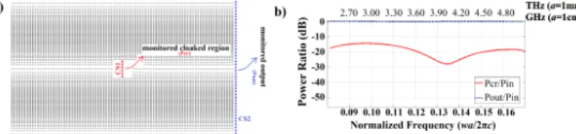
The foremost superiority of the present approach is due to the fact that Maxwell’s equations are scalable. It is fairly easy to find transparent dielectric materials in any part of the electromagnetic spectrum. As a result, one can implement the present cloaking idea to be operated in different regions such as microwaves by manipulations performed at the millimeter range. Besides spherical aberration, there is another important concept depending on ray analyzes of the HS GRIN medium. The length of the structure in the x direction should be multiplication of the half-pitch length /π α, with an integer coefficient. In this way, the output profile of the wave could almost be kept the same with the input plane wave. In other words, image of the input occurs at the half pitch length. Considering this condition, the length of the device is determined without any trials and errors to be 128a. Schematic of the cloaking structure is given in Fig. 3(a). Stacked alignment causes the incident beam to be separated into equal parts due to the well-known focusing characteristic of the GRIN medium.
Additionally, transmission efficiency is given in Fig. 3(b). The efficiency is calculated via finite-difference time-domain (FDTD) [22,23] method and the result is given in dB units.
Fig. 3. (a) The geometry of the cloaking device with two stacked GRIN PC waveguides is shown. (b) Power ratios of the cloaked region and output over the input signal.
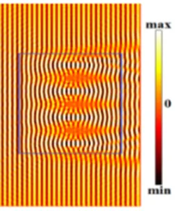
Dashed lines in Fig. 3(a) represent cross sections along the cloaked region, CS1, and output surface CS2. In Fig. 3(b) corresponding power ratios are plotted. The figure depicts that the input (Pin) and output (Pout) powers are almost the same (lines stay at 0 dB level), lossless transmission is achieved. In addition, the ratio between powers through the cloaked region and the output is over 20 dB. In other words, the signal power at the cloaked region (Pcr) is less than one percent of the power of the output signal for almost all over the operating band. Performed FDTD results under plane wave illumination are given in Fig. 4. As seen in the figure, the beam is diverged by the cloaking device and converged afterwards. By this means, the cloaked regions are barely affected by the electromagnetic beam. In order to determine a figure of merit regarding how well the device hides an object, metallic rods are located at the cloaked regions. Lossy feature and high permittivity value of the metals would dramatically affect the hiding performance. However, Fig. 4 indicates that desirably flat output phasefronts are achieved all over the space. On the other hand, measured power is as high as that of the incoming wave. This elucidates that propagating wave is not affected by the lossy metallic objects due to cloaking action.
Intensity is near zero at the cloaked regions where metallic rods are positioned, and the output phasefront profile of the beam is kept almost the same as that of the input wave. The proposed cloaking device has a bandwidth of 10.88% wherea/λ=
[
0.113,0.126]
. If we assumea=1cm, then operating frequencies are ω π/ 2 =[
3.39,3.78]
GHz. The device length in the longitudinal direction with respect to the operating center wavelength is15.25λ. Total hiding area is 1.42λ2that corresponds 100cm2when the central frequency is equal to 3.59GHz.
Differently from the previous cloaking studies with conformal mapping or coordinate transformation implemented by metamaterials, the present study achieves the broad band operation reducing the chromatic aberration. Besides, cloaked region is maximized via preventing spherical aberration. Moreover, the present device operates for dual polarization and that is a novel feature of the study. To the best of authors’ knowledge, polarization independency or dual polarization is not considered yet in the literature. One can easily infer that the specified limits of the effective index values enable our design to operate with both polarization states:
(
)
(
)
0 lim 0, or lim 0, r h TE TM TE TM n n n n λ→ δ − = ε→ε δ − = (3)whereδ nTE−nTM symbolizes difference between corresponding effective indices of different transverse modes, TE and TM. Reducing this value to the proximity of zero decreases system’s susceptibility to electric field’s oscillation direction. As mentioned before in the paper, the medium is generated regarding TM case and also the structures are excited by TM waves in all simulations. In order to verify the system’s polarization independency, same structures are excited by TE waves and results are given in Fig. 5. Predetermined structural
parameters enable the device to operate also for TE case. However, the geometry of the design is based on TM polarization. Therefore, the pitch length of the GRIN medium slightly varies for TE polarization. This leads to acceptable wavefront errors.
Fig. 4. (a) Schematic of the cloaking device with four stacked GRIN PC waveguides (three cloaked regions) is shown. Electric field (Ez) distributions for three frequencies:
(b)a/λ =0.1130,(c)a/λ=0.1195and (d) a/λ=0.1260under the plane wave excitation. The boundaries are determined keeping phase mismatch below 10%.
One can question the compactness of the design and manipulation of the area of the cloaking region. Increasing the gradient coefficient by lowering the transverse dimension of the design allows shorter oscillation period of the rays inside the medium and strong focusing. As a result, cloaking region decreases due to dimensional reduction along the y-direction but at the same time contrast power ratio should increase because of the large index gradient. Instead of utilizing low refractive index for the host material, we can use large refractive index to implement high index gradient. Then the index matching at the interface between the cloaking device and free-space should be carefully handled.
Fig. 5. Hz field distribution regarding TE polarization plane wave excitation at the normalized
frequency a/λ=0.1650. 4. Conclusion
In conclusion, we designed a novel unidirectional cloaking device using stacked 2D GRIN media. The design is constructed with dielectric rods located in air background. High transmission efficiency and relatively large arbitrary shaped object cloaking are achieved. Moreover, GRIN feature and flat surface of the structure enable it to cloak under any spatial size of the incoming wave. The proposed broad band all-dielectric structure cloaking design is non-resonance type and also has low-loss characteristics. The scalability of the Maxwell equations provides the structure to be a potential device for visible or lower frequency ranges. In addition, implementation methods of the GRIN PC provide feasibility for fabrication of continuous GRIN medium. This study may lead constructing more improved broad band cloaking devices operating in either two- or even three- dimensions.
Acknowledgments
The authors gratefully acknowledge the financial support of the Scientific and Technological Research Council of Turkey (TUBITAK), project 110T306. HK acknowledges partial support from the Turkish Academy of Sciences.