2020, VOL. 4, NO: 2, 98-104 www.dergipark.gov.tr/ijastech
98
Advisor Based Modelling of Regenerative Braking Performance of Electric
Vehicles at Different Road Slopes
M. Akif Kunt
*0000-0001-5710-7253
Department of Motor Vehicles and Transportation Technologies, Tavsanlı Vocational School, Dumlupinar University, Kutahya, 43300, Turkey
---1. Introduction
Need for renewable energy sources increased day by day in the world, in order to struggle with climate change and en-hance power safety [1]. When we look into new generation vehicles manufactured today, it is seen that weight of vehi-cles and fuel consumption are decreased constantly and more saving vehicles are manufactured [2]. Electric vehicle is the name given to vehicles that provide motional energy by electrical energy. By generalizing such vehicles, it is planned to decrease emission oscillation, caused by engine vehicles running with fossil origin fuels. Studies on manu-facture of electric vehicles in economic terms besides their environmental benefits continue [3]. Basic operation princi-ple of electric vehicles is based on usage of power stored in the battery for activating the electric engines. Today, both electric and
hybrid usages are available. As of 2016, many automotive manufacturer produce electric vehicles. The problem with
electric vehicles is the high cost despite their short range distance when compared to fossil fuel vehicles [4]. Alt-hough electric vehicles have many advantages, reasons such as short distance of range and long term of charging create serious disadvantages. In internal combustion engines, the kinetic energy generated during braking is transformed into heat energy by means of mechanical friction and it is con-sumed; and such situation sometimes composes 50% of all effective traction energy on average. The kinetic energy consumed for nothing is transformed into electric energy thanks to regenerative braking system and stored in batter-ies; and the obtained beneficial energy is used for increased range in electric vehicles. In this way, an effective im-provement is made for solving range problem of the vehicle and total energy efficiency of the vehicle increases. Recov-ery of energy of electric engines used in electric and hybrid electric vehicles, resourcing from opposite electromotor force during braking results in higher system efficiency and Abstract
In this study, an electric vehicle model, which has 75kW AC asynchronous engine and 25kW Nickel-metal hydride (Nimh) batteries, has been composed by means of (ADVISOR-Advanced Vehicle Simulator) program. During the driv-ing cycle formed for the designed electric vehicle, chargdriv-ing state of batteries, braking losses, battery temperatures and fuel consumption have been analyzed at different road slopes. The study has shown that power to batteries is provided by regenerative braking at all slopes and if the slope is downhill, more energy is stored into batteries due to regenerative braking. In simulation of the modelled device, maximum brake power loss of 4.43 kW has decreased at road slope of ∝= −%1.5 by means of regenerative recovery. At road slope of 𝛼 = −4.5, the highest charging level has been obtained as 99.1%. With regenerated recov-ery, 𝛼 = −4.5, 𝛼 = 0, 𝛼 = 4.5 on road slopes % 57, % 5, % 2 fuel savings have been achieved respectively.
Keywords: ADVISOR, battery charge, electric vehicle, regenerative braking, road slope
* Corresponding author M. AkifKunt
[email protected] Adress: Department of Motor Vehi-cles, Tavsanlı Vocational School, Dumlupinar University, Kutahya, Turkey Tel:+902746148672 Fax:+902746148673 Researh Article Manuscript Received 09.04.2020 Revised 04.05.2020 Accepted 23.05.2020 Doi: 10.30939/ijastech..717097
increase of battery charge and range. Regenerative braking system decreases fuel cost and emissions and increases ve-hicle range distance [5]. ADVISOR veve-hicle simulation pro-gram is used in modelling of vehicles by means of different configurations and in analyzing their performance in differ-ent driving cycles. There are many studies related to analy-sis of performance of electric and hybrid electric vehicles by means of such program [6-11]. Kinetic energy recovery systems have been used firstly in race cars. Researches have been made in locomotives [12], tracks [13], buses [14] and automobiles [15] aiming at enhancing recovery from brak-ing energy. Studies related to recovery of kinetic energy in electric and hybrid vehicles continue [16]. Yang et al., in their study on electric scooter, have stated that regenerative energy recovery is more suitable for current systems in-cluded in electric vehicles [17]. In a simulation of electric vehicles, made for recovery of energy lost during braking, it has been foreseen that an energy saving of 25% can be made by KERS for intra-city usage [18]. The road slope is very important for electric vehicles in terms of vehicle con-trol and fuel economy. Road slope also has an effect on establishing more effective control strategies for regenera-tive braking system [19]. Many parameters must be consid-ered to improve energy recovery in electric vehicles. The most important of these parameters are the mass of the ve-hicle, the road slope, and the type of road [20]. Although there are models defining the traffic of electric vehicles [21-27], there are not many studies investigating the effects of the slope of the road determining the performance of these vehicles. In real driving conditions, each road has a certain slope and the road slope has an effect on the driver's behav-ior [28-31]. The effect of regenerative braking performance on downhill situations in electric vehicles is not a subject of much research due to the lack of observational data and difficulty in meeting experimental conditions [32]. During daily vehicle use, especially on urban roads, short-term downhill ups and downs up to α=0-4.5° slope are frequently observed. It is therefore important to investigate regenera-tive gains in short-term road slopes of electric vehicles. 2. Modelling of the Vehicle
2.1 Forces Affecting the Movement of the Vehicle
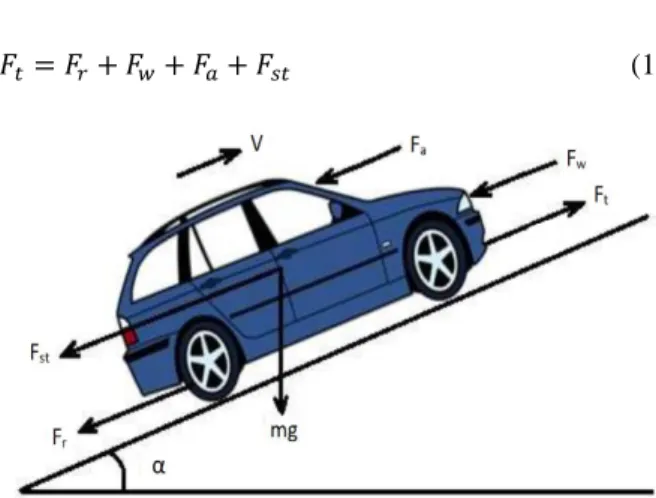
Forces affecting the movement of the vehicle can be classified into two groups as resistance forces that resist movement of the vehicle and affected by environmental factors and as moving (traction) forces that enable transmis-sion of the power generated by the engine to the wheels [33]. Resistance forces consist of rolling resistance on vehi-cles as shown in equation 1 (𝐹𝑟), aerodynamic (wind) fric-tion (𝐹𝑤), inertial resistance that the vehicle should exceed (𝐹𝑎) and inclination resistance (𝐹𝑠𝑡) [34]. In figure 1, forces affecting the vehicle are shown [35]. In Table 1, force pa-rameters from which the vehicle is affected are shown.
𝐹𝑡= 𝐹𝑟+ 𝐹𝑤+ 𝐹𝑎+ 𝐹𝑠𝑡 (1)
Fig. 1. Forces acting on the vehicle
𝐹𝑟= 𝑐𝑟,𝑟𝑜𝑚𝑔 + 𝑐𝑟,𝑟1𝑚𝑔𝑉 (2) Equation (2), 𝑐𝑟,𝑟𝑜, 𝑐𝑟,𝑟1 indicate 1st and 2nd Rolling resistance coefficients, 𝑚- indicates the vehicle mass, g- indicates gravity acceleration and V- indicates vehicle speed.
𝐹𝑤= 1
2𝜌 𝐶𝑑𝐴𝑓𝑉
2 (3) Equation (3), 𝜌- indicates air density, 𝐶𝑑- indicates aer-odynamic friction coefficient, 𝐴𝑓- indicates frontal cross-sectional area.
𝐹𝑎= 𝑚 𝑀𝑖 𝑑𝑉
𝑑𝑇 (4) Equation (4), 𝑀𝑖- indicates inertial mass factor,
𝑑𝑉 𝑑𝑇- in-dicates vehicle acceleration.
𝐹𝑠𝑡= 𝑚𝑔 sin 𝛼
(5) Equation (5), 𝛼- indicates the slope of the road [34]. 2.2 Regenerative Braking Equations
The energy emerging during braking (𝑊𝑏) is equal to the total moving power (∫ −𝑃𝑣(𝑡)𝑑𝑡
𝑡
0 ) from the start of braking until the moment stop of the vehicle which is assumed to be lack of rolling resistance of the wheels and air resistance (aerodynamic) occurring during the movement of the vehi-cle for ideal position.
𝑊𝑏= −𝑊𝑑= ∫ −𝑃𝑣(𝑡) 𝑑𝑡 𝑡
0
(6)
Under real conditions, it is not possible for such state to realize. As the speed of the vehicle decreases, some of the energy is spent for frictions. The amount of net brake
ener-100 gy to be stored in KERS after losses is related to modelling
of moving and power transmission organs of the vehicle. Besides the energy, which is not gained during braking by means of KERS (𝑷𝒃𝒓,𝒍𝒐𝒔𝒔), a part of the obtained energy is lost due to reasons such as loss occurring as a result of aer-odynamic
factors (𝑷
𝒂,𝒍𝒐𝒔𝒔),
transformation of re-cycled energy into electric energy, losses occurring during its transmission and regulation (𝑷𝒕𝒓,𝒍𝒐𝒔𝒔), losses of electric en-gine, losses of mechanical parts (𝑷𝒎𝒆𝒌,𝒍𝒐𝒔𝒔), losses occurring during charging and de-charging transactions (𝑷𝒃𝒂𝒕), de-pending upon the type of battery used in storing unit (lead, acid, lithium-ion, nickel-cadmium, ultra-capacitor,etc.). Net energy (𝑾𝑲𝑬𝑹𝑺) re-gained by means of KERS after suchlosses in orderto be stored in the battery can be shown as follows [4].𝑊𝐾𝐸𝑅𝑆= ∫ (−𝑃𝑣(𝑡) + 𝑃𝑏𝑟,𝑙𝑜𝑠𝑠(𝑡) + 𝑃𝑎,𝑙𝑜𝑠𝑠(𝑡) + 𝑡
0
𝑃𝑡𝑟,𝑙𝑜𝑠𝑠+ 𝑃𝑒𝑚,𝑙𝑜𝑠𝑠+ 𝑃𝑚𝑒𝑘,𝑙𝑜𝑠𝑠+ 𝑃𝑏𝑎𝑡,𝑙𝑜𝑠𝑠)𝑑𝑡
(7)
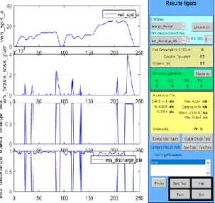
2.3Vehicle Design and Analysis by Means of Advisor ADVISOR-Advanced Vehicle Simulator is a system ve-hicle formed for veve-hicle modelling in MATLAB/Simulink environment by NREL-National Renewable Energy Labor-atory located in USA. It offers a flexible and sound model, data and instruction file used to measure fuel saving, per-formance and emission in various driving cycles of vehicles included in different classes. In Figure 2, Advisor pro-gram’s introductory screen of the vehicle in shown. After entering the parameters required for vehicle definition, the second stage is followed, in which options for driving cy-cles for testing the electric vehicle are offered. In Table 1, the characteristics of the defined vehicle for the simulation are given in “drive cycle” part, driving cycle has been cho-sen as ‘CYC_IM240’ and number of cycle has been chocho-sen as 1.
Fig. 2. Introductory screen of Advisor program
Table 1. Technical parameters of simulation
Parameter Unit Data
Vehicle weight 𝑘𝑔 1429
Tyre type SAE J2452,
P205/60R15 Wind resistance coefficien
t
0.3 Rolling resistance coeffici
ent
0.009 Vehicle center of gravity
height
𝑚 0.57
Air density 𝑘𝑔 𝑚⁄ 3 1.2
Motor type AC cont. ind.
Motor power 𝑘𝑊 75
Battery type Nimh
Total number of battery modules
65 Nominal voltage (for 1
module)
6.9 Total battery mass 𝑘𝑔 234
Gearbox One shift auto
matic Energy consumed by har
dware (fixed)
𝑊 700
IM240 test is the ones carried out for exhaust emission inspection and maintenance. Total test duration is 240 sec-onds and total cycle distance is 3.15 km (1.96 miles). Av-erage speed is 47.08 km/h (29.4 mile/h) and maximum speed is 91.25 km/h (57 mile/h. In line with the parameters determined for such stage in Advisor program, when simu-lation of the electric vehicle during active mode of regener-ative brake is on, results shown in Figure 3 are obtained.
3. Analysis of Regenerative Braking State
In Figure 4, energy change occurring in batter group pf vehicle as per IM240 driving cycle under ∝= 0, ∝= 1.5 (uphill) and ∝= −1.5 (downhill) conditions is shown. Traction value should be negative in order to obtain regen-erative braking power and energy. In the case when traction is negative, entry of power, obtained from regenerative braking and measured, occurs. Such state is shown as the place between curves in Figure 5. During time intervals of 19-25 s, 37-40 s, 66-68 s, 75-76 s, 85-95 s, 116-121 s, 129-136 s, 151-152 s, 206-209 s and 221-242 seconds in which slowing is in question according to driving cycle, regenera-tive braking is enhanced. The area between the curves shows the power obtained by means of regeneration. Ac-cording to the driving cycle, 2.09 kW, 2.17 kW and 1.28 kW recovery has been achieved for ∝= 0 , ∝= −1.5 (downhill) and ∝= 1.5 (uphill) road slopes, respectively. There has been obtained a 4% regenerative gain difference for a cycle of 240 seconds between ∝= 0 and the ∝= −1.5 (downhill) slope.
In Figure 5, the change in brake power loss is shown ac-cording to IM240 driving cycle under ∝= 0 , ∝= 1.5 (uphill) and ∝= −1.5 (downhill) conditions. During time intervals of 19-25 s, 37-40 s, 66-68 s, 75-76 s, 85-95 s, 116-121 s, 129-136 s, 151-152 s, 206-209 s and 221-242 sec-onds in which slowing is in question according to driving cycle, brake pads are worn less thanks to regenerative brak-ing. During the driving cycle, braking energy loss has oc-curred maximum in 221-242 seconds. In such time interval, less braking loss has occurred due to regenerative braking. During downside inclination, acceleration due to downhill increases the braking load. The biggest braking power loss in different road slopes has occurred on ∝= −1.5 road slope. In Table 2, braking power loss according to road slope is shown.
In Figure 6, the change in consumed fuel amount is shown according to cycle 1 in IM240 driving cycle on dif-ferent road slopes. On downhill roads, while 0.9 l gasoline equivalent fuel is consumed at ∝= −4.5 slope during regenerative driving, 1.1 l gasoline equivalent fuel is con-sumed during non-regenerative driving. When road slope changes as uphill incline, fuel consumption increases in both situations due to the increase in rolling resistance. While 4.8 l gasoline equivalent fuel is consumed at ∝= 4.5 slope during regenerative driving, 4.9 l gasoline equiv-alent fuel is consumed during non-regenerative driving.
(a) ∝= 0 road slope
(b) ∝= −1.5 (downhill) road slope
(c) ∝= 1.5 (uphill) road slope Fig. 4. Graphic showing the energy change in battery for unit if
time during driving cycle -40 -30 -20 -10 0 10 20 30 0 100 200 d E/ d T [ kW] Time [s] with regen. without regen. -50 -40 -30 -20 -10 0 10 20 30 0 100 200 d E/ d t [ kW] Time [s] with regen. without regen. -45 -35 -25 -15 -5 5 15 25 0 100 200 d E/ d t [ kW] Time (s) with regen. without regen.
102 (a) ∝= 0 road slope
(b) ∝= −1.5 (downhill) road slope
(c) ∝= 1.5 (uphill) road slope
Fig. 5. Braking energy loss depending on time in driving
Table 2. Braking power loss according to different road slopes Road slopes ∝= 1.5 ∝= 0 ∝= −1.5 with regen. (kW) 11.98 13.98 16.13 without regen. (kW) 16.02 18.12 20.56 Recovery (kW) 4.04 4.14 4.43
Fig. 6. Amount of fuel consumed according to road slope In Figure 7, the state of charge (SOC) change depending on time is shown for different road slopes. During downhill driving, as the road slope accelerates the vehicle, battery charge decreases at minimum rate. On the contrary, during uphill driving, as the incline resistance increases, battery charge decreases at maximum rate. During the simulation carried out, the lowest charge level at the end of driving cycle is 93% at road slope of 𝛼 = 4.5, and the highest charge level is 99.1% at road slope of 𝛼 = −4.5. With regenerated recovery, 𝛼 = −4.5 , 𝛼 = −3 , 𝛼 = −1.5 , 𝛼 = 0, 𝛼 = 1.5, 𝛼 = 3, 𝛼 = 4.5 on road slopes % 57, % 18, % 11, % 5, % 4.7, % 4, % 2 fuel savings have been achieved respectively.
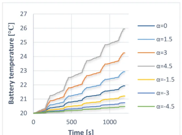
In Figure 8, shows the battery temperature change with regeneration state according to 5 driving cycle. Tempera-ture of selected Nimh battery is 20 °C during the beginning of the cycle. When driving cycle is run for 1 driving cycle, a negligible temperature increase has occurred, when com-pared to the beginning temperature of the battery. At the end of 5 cycles, the lowest battery temperature increased by 5% (20.9°C) on the -4.5% road slope and by 30% on the 4.5% (26.05°C) road slope. When batteries are subjected to a large number of charges and discharges with regeneration effect, undesirable chemical reactions have increased, re-sulting in a greater increase in the battery temperature. The charge-discharge status of the battery affects the battery temperature [36]. 0 5 10 15 20 25 30 35 40 45 50 0 100 200 Br ake p o we r l o ss [kW] Time [s] with regen. without regen. 0 5 10 15 20 25 30 35 40 0 100 200 Br ake p o we r l o ss [kW] Time [s] with regen. without regen. 0 5 10 15 20 25 30 35 40 45 0 100 200 Br ake p o we r l o ss [kW] Time [s] with regen. without regen.
Fig. 7. The state of charge (SOC) change depending on time at different road slopes
Fig. 8. The battery temperature and the vehicle speed change depending on time at different road slopes (with regen.)
Fig. 9. The battery temperature and the vehicle speed change depending on time at different road slopes
(without regen.)
In Figure 9, shows the battery temperature change with-out regeneration state according to 5 driving cycle. For all road slopes, time-dependent battery temperatures have increased. However, in the without regeneration state, the lack of battery charge resulted in lower battery temperature compared to the regenerated state. At the end of 5 cycles, the lowest battery temperature increased by 3% (20.5°C) on the -4.5% road slope and by 29% on the 4.5% (25.8°C) road slope. Reduced road slope caused the battery to heat up less.
3. Conclusions
The fact that the slope of the road is in the direction of uphill reduces the regenerative gain. However, regenerative gain can be achieved on slopes up to 4.5% slope. The road slope, increasing uphill during the operation of driving cy-cle of the related electric vehicy-cle model, helps slowing and results in less brake power loss during braking. However, in such situation, recovery by regenerative braking has oc-curred less. The road slope increasing downhill has de-creased fuel consumption and battery discharge, and result-ed in highest value of the state of charge (SOC). During driving cycle in which battery charge-discharge number is high, higher battery temperature has occurred. In this study, stabile cargo load has been taken into consideration and in following studies effect of Cargo load on recovery shall be examined at different road slopes. Selecting lower road slope routes by pre-detecting the road slope with the GPS system will increase the range of electric vehicles.
References
[1] Amaç, A. E., Şahin, Y. G., Aras, F. (2009). Analysis and simulation of automotive electrical system with ADVISOR. 5th International Advanced Technologies Symposium (IATS'09), Karabuk, Turkey.
[2] Arslan, M. Ö. (2019). Fundamentals & numerical investiga-tions of commercial vehicle aerodynamics. Available online:
https://polen.itu.edu.tr/xmlui/handle/11527/9968.
[3] Chen, J. J., Zhou, L. X., Ning, X. B., Zhao, C. L. (2013). Design of hybrid electric bus on regenerative braking system.
Applied Mechanics and Materials, 300, 333-337.
[4] Demirkale, B., Güven, F. (2017). Investigation of kinetic energy recovery systems usage in electric vehicles. Sakarya
University Journal of Science, 21, 1550-1557.
[5] EPA New York City Cycle (NYCC). (2019). Emission Test Cycle, https://www.dieselnet.com/standards/cycles/nycc.php [6] Gantt, L. R. (2019). Energy losses for propelling and braking
conditions of an electric vehicle. Available online:
https://vtechworks.lib.vt.edu/handle/10919/32879.
[7] Guirong, Z. (2012).Research of the regenerative braking and energy recovery system for electric vehicle. World Automa-0,9 0,91 0,92 0,93 0,94 0,95 0,96 0,97 0,98 0,99 1 1,01 0 100 200 State o f c h ar ge [ % ] Time [s] α=0 α=1.5 α=3 α=4.5 α=-1.5 α=-3 α=-4.5 20 21 22 23 24 25 26 27 0 500 1000 Batter y te mp e ratu re [ °C] Time [s] α=0 α=1.5 α=3 α=4.5 α=-1.5 α=-3 α=-4.5 20 21 22 23 24 25 26 27 0 500 1000 Batter y te mp e ratu re [ °C] Time [s] α=0 α=1.5 α=3 α=4.5 α=-1.5 α=-3 α=-4.5
104
tion Congress, Puerto Vallarta, Mexico.
[8] Güven, F., Rende, H. (2017). Importance of material selec-tion in design of electric vehicles. Engineer and Machinery, 58, 81-95.
[9] Whiting, J. M. W. (1982). A regenetive braking system Ford.
Journal of Science and Technology, 48, 170-175.
[10] Kunt, M. A. (2016). Use of thermoelectric generators in the internal combustion engine waste heat recovery. El-Cezeri
Journal of Science and Engineering, 3, 192-203.
[11] Kunt, M. A. (2019). A design of a liquid cooling thermoelec-tric generator system for the exhaust systems of internal com-bustion engines and experimental study on the effect refriger-ant fluid qurefriger-antity on recovery performance. Pamukkale
Uni-versity Journal of Engineering Sciences, 25, 7-12.
[12] Larminie, J., Lowry, J. (2012). Electric vehicle technology explained. 2nd edition, John Willey&Sons.
[13] Malode, S., Adware, R. (2016). Regenerative braking system in electric vehicles. International Research Journal of
Engi-neering and Technology, 3, 394-400.
[14] Markel ,T., Brooker, A., Hendricks, T., Johnson, V., Kelly, K., Kramer, B., Wipke, K. (2002). ADVISOR: a systems analysis tool for advanced vehicle modeling. Journal of
Pow-er Sources, 10, 255-266,
[15] Pugi, L., Pagliai, M., Nocentini, A., Lutzemberger, G., Pretto, A. (2017). Design of a hydraulic servo-actuation fed by a re-generative braking system. Applied Energy, 187, 96-115. [16] Rashid, M. I., Danial, H. (2017). ADVISOR simulation and
performance test of split plug-in hybrid electric vehicle con-version. Energy Procedia, 105, 1408–1413.
[17] Suvak, H., Erşan, K. (2016). The simulation of a full electric vehicle using the city cycle. International Journal of
Automo-tive Engineering and Technologies, 5, 38-46.
[18] Bian, J., Qiu, B. (2018). Effect of road gradient on regenera-tive braking energy in a pure electric vehicle. Proceedings of
the Institution of Mechanical Engineers, Part D: Journal of Automobile Engineering, 232, 1736–1746.
[19] Boisvert, M., Mammosser, D., Micheau, P., Desrochers, A. (2013). Comparison of two strategies for optimal regenerative braking, with their sensitivity to variations in mass, slope and road condition. IFAC Proceedings, 46, 626-630.
[20] Cocron, P., Krems, J. F. (2013). Driver perceptions of the safety implications of quiet electric vehicles. Accident
Analy-sis & Prevention, 58, 122-131.
[21] Millo, F., Rolando, L., Mallamo, F., Fuso, R. (2013). Devel-opment of an optimal strategy for the energy management of a range-extended electric vehicle with additional noise, vibra-tion and harshness constraints. Proceedings of the Instituvibra-tion
of Mechanical Engineers, Part D: Journal of Automobile En-gineering, 227, 4–16.
[22] Silva, C., Ross, M., Farias, T. (2009). Evaluation of energy consumption, emissions and cost of plug-in hybrid vehicles.
Energy Conversion Management, 50, 1635-1643.
[23] Faria, R., Marques, P., Moura, P. (2013). Impact of the tricity mix and use profile in the life-cycle assessment of elec-tric vehicles. Renewable Sustainable Energy Reviews, 24,
271-287.
[24] Hawkins, T. R., Singh, B., Majeau, B. G. (2013). Compara-tive environmental life cycle assessment of conventional and electric vehicles. Journal of Industrial Ecology, 17, 53-64. [25] Ang, S. C., Deng, C., Tang, T. Q., Qian, Y. S. (2013).
Elec-tric vehicle’s energy consumption of car-following models.
Nonlinear Dynamics, 71, 323-329.
[26] Shen, W., Han, W. J., Chock, D. (2012). Well-to-wheels life-cycle analysis of alternative fuels and vehicle technologies in China. Energy Policy, 49, 296-307.
[27] Zhu, W. X., Yu, R. L. (2012). Nonlinear analysis of traffic flow on a gradient highway. Physica A, 4, 954-965.
[28] Zhu, W. X., Zhang, C. H. (2013). Analysis of energy dissipa-tion in traffic flow with a variable slope. Physica A, 16, 3301-3307.
[29] Gupta, A. K., Katiyar, V. K. (2006). Phase transition of traf-fic states with on-ramp. Physica A, 371, 674-682.
[30] Komada, K., Masukura, S., Nagatani, T. (2009). Effect of gravitational force upon traffic flow with gradients. Physica A, 388, 14, 2880-2894.
[31] Liu, K., Yamamato, T., Morikawa, T. (2017). Impact of road gradient on energy consumption of electric vehicles.
Trans-portation Research Part D, 54, 74-81.
[32] Walsh, J., Muneer, T., Celik, A. N. (2011). Design and analy-sis of kinetic energy recovery system for automobiles.
Jour-nal of Renewable and Sustainable Energy, 3, 849-856.
[33] Zhang, Y., Zhang, C. (2011). ADVISOR and its application in electric vehicle simulation. Proceedings of the 30th
Chi-nese Control Conference, Yantai, China.
[34] Husain, I., Islam, M. S. (1999). Design, modeling and simula-tion of an electric vehicle system, SAE Technical Paper (No. 1999-01-1149)
[35] Erdem, Y., Taci, M. S. (2018). Effect of regenerative braking and power analysis in electric vehicles. Journal of Current
Researches on Engineering, Science and Technology, 4, 75-8.
[36] Güven, E. C., Gedik, K. (2019). Environmental management of end-of-life electric vehicle batteries. Igdır University