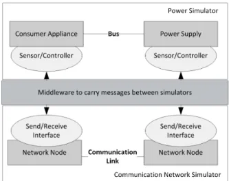
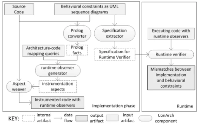
A run-time verification framework for smart grid applications implemented on simulation frameworks
Tam metin
Şekil
Benzer Belgeler
The main objective of this optimal power flow control is to acquire the complete voltage angle and the magnitude information for each bus in power systems, which is
For the overload states, since the probability that the queue length is zero at some time epoch is negligible, fluid flow approximation gives accurate results
The comparison of the peak amplitude behavior with the sheet resistance and with the behaviors at selected voltages (Fig. 3b) suggest that observed modulation with the set
• Abhinav Dhall, Monash University • Jyoti Joshi Dhall, Monash University • Sergio Escalera, University of Barcelona • Jeffrey Girard, Carnegie Mellon University • Laszlo
either chronic hypertension (38) or chronic renal disease was shown to increase SOD and GPx activity, but not the antioxidant effects of CAT, implicating that the protective effect
NO 2 uptake properties of ceria promoted alumina support materials (i.e. 10Ce/Al and 20Ce/Al) are also investigated in stepwise NO 2 adsorption experiments. via FTIR
Tunç Okan’›n Otobüs bafll›kl› filmi masallar›n kaç›n›lmaz motiflerinden biri olan yolcu- luk motifi üzerine kurulmufl bir senaryoya sahiptir.. Bu çal›flma
During the last centuries of the Ottoman state, the imperial elite initiated the process of Westernization and adopted their state's formal integration with the European state
