Introduction
Wireless power transfer (WPT) systems can be categorized into radiative and non-radiative systems [1, 2]. Radiative systems utilize highly directed receiver and transmitter antenae and work at microwave frequencies. Their efficiency is usually lower than that of non-radiative sys-tems and a line of sight propagation is needed; however, power can be transferred to very long distances. On the other hand, non-radiative systems usually exhibit greater efficiency, but they are limited to very short power transfer distances. In these systems, power transfer is car-ried out via near-field coupling. Coupling is achieved through either electric field (capacitive coupling) or magnetic field (inductive coupling).
Today, due to very broad coverage of existing electrical grids, long-range wireless power transfer systems are not needed in all but several very specific applications. However, widespread use of mobile devices and battery powered vehicles open up a new usage for wireless power transfer at medium range (midrange) distances, from several centimetres to a couple of meters. For mid-range applications, radiative systems are not convenient as they are based on far-field radiation. Capacitive coupling based non-radiative systems are not safe for daily use applications as the electric field near the transmitter and receiver devices interacts strongly with surrounding objects including humans. Magnetic field interacts weakly with surrounding objects, yet the power trans-fer distances in traditional inductive coupling systems are quite low (a couple of centimetres) for charging mobile devices and electric vehicles compared with several tens of centimetres. The magnetically coupled loops, when resonated out, was proposed for use in midrange pow-er transfpow-er [1, 3]. It has been shown that one can transfpow-er powpow-er at a distance sevpow-eral times the radius or the length of the loops in magnetically coupled resonant loops [4, 5]. Moreover, when the loops operate in a strongly coupled regime, it is almost possible to achieve a dis-tance-independent power transfer efficiency.
A Circuit Model-Based Analysis of Magnetically Coupled
Resonant Loops in Wireless Power Transfer Systems
Seyit Ahmet Sis
Department of Electrical-Electronics Engineering, Balıkesir University School of Engineering, Balıkesir, Turkey
Corresponding Author:
Seyit Ahmet Sis
E-mail: [email protected] Received: 17.11.2017 Accepted: 26.02.2018 © Copyright 2018 by Electrica Available online at http://electrica.istanbul.edu.tr DOI: 10.26650/electrica.2018.55345
Cite this article as: S. A. Sis, “A Circuit Model Based Analysis of Magnetically Coupled Resonant Loops in Wireless Power Transfer Systems “, Electrica, vol.
18, no: 2, pp. 159-166, 2018.
ABSTRACT
Magnetically coupled resonant loops can be represented by a lumped element circuit model. Each parameter in the lumped element model can be expressed as a function of loop geometry and the separation between the loops; therefore, the geometry can be systematically changed, and the power transfer efficiency of the coupled loops can be predicted. This paper presents a simulation-based efficiency analysis for wireless power transfer systems utilizing magnetically coupled resonant loops. The behavior of power transfer efficiency is studied for various loop geometry parameters, and the simulation results are presented in detail. These results clearly show that there is a trade-off between peak efficiency and critical coupling distance, both of which depend on the loop size, frequency of operation, and source-load impedances. To verify the accuracy model, two identical circular loops are fabricated and measured, and the measurement results agree well with the model.
Magnetically coupled resonant loops can be analysed either by a coupled mode theory (CMT) [6,7] or by using an equiva-lent circuit model. It has been shown that an equivaequiva-lent circuit model is simpler and quite accurate for the analysis of resonant magnetically coupled loops [7]. Numerous works, based on equivalent circuit models, have been reported [7-15].
This paper presents an equivalent circuit model based analysis for WPTs using magnetically coupled resonant loops. As com-pared to previously reported works on circuit model based analysis of WPTs, this work presents comprehensive simulation results by systematically changing the geometry parameters and source & load resistances. Using these simulation results, the effect of loop size and source & load resistancess on effi-ciency response in both weakly and strongly coupled regimes is presented. The conditions for operating in each of these re-gimes are examined in terms of loop size and load & source resistances for circular loops. To verify the model, two identical circular loops are fabricated and measured. Measurement re-sults exhibit good agreement with the model.
An Equivalent Circuit Model for Inductively Coupled Resonant Loops
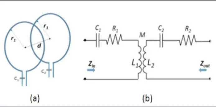
The magnetically coupled resonant loops, as in Figure 1 a, can be represented by a circuit model shown in Figure 1 b. In this model, the magnetic coupling between the loops is represent-ed by a mutual inductance (M). The components L1, R1 and C1 are the self-inductance, parasitic resistance and the resonance capacitance for the transmitting loop, respectively. Similarly, L2, R2 and C2 are the same parameters for the receiving loop.
Each component in the circuit is dependent on the geometry parameters of the loops.
The self-inductance (L1,2) for a circular loop as a function of loop radius (r), radius of the wire (a) and number of turns (N) can be found as follows [4]:
(1.a)L1,2=N2µ0 (r - a)(r + a) ( 2k- k)K(k) - ( 2k)E(k)
⎡ ⎣
⎢ ⎤
⎦ ⎥
where K and E are the complete elliptic integrals of the first and second kind as follows
(1.b)
K(k) =
dβ
1- k
2sin
2β
0 π /2∫
(1.c)E(k) =
dβ 1- k
2sin
2β
0 π /2∫
(1.d)k = 4(r - a)(r + a)
(2r)
2+
(2a)
2.
where μ0 is the magnetic permeability of the air. The parasitic resistance (R1,2) includes the effect of both conductor loss (Rc) and the radiation loss (Rr) and can be calculated as follows [16]:R
r=
20N
2π
2(2πr
λ
)
4(Ω)
(2.a) (2.b)R
c=
2πrN
2πρ
µ
0ω
2σ
(Ω)
(2.c)R = R
c+
R
rwhere ω is the radial frequency, λ is the wavelength at the op-erating frequency and σ is the conductivity of the wire. The mutual inductance between the loops can be calculated as function of loop geometry and separation between the loops (d) as follows [4]:
(3a)
M = N
2µ
0r
1r
2((2
l
−
l)F(l) − 2
l
E(l)) H
where K and E are the complete elliptic integrals of the first and second kind as follows:
(3b)
F(l) =
dβ
1− l
2sin
2β
0 π /2∫
(3c)E(l) =
dβ 1− l
2sin
2β
0 π /2∫
(3d)l =
4r
1r
2(r
1+
r
2)
2+
d
2.
Analysis of Circuit Model for Efficiency Calculations For efficiency calculations, an RF source with an internal re-sistance (RS) and a load resistance (RL) are connected to the input and output of the model, respectively, as shown inFig-Figure 1. a, b. General depiction of magnetically coupled
ure 2. A mathematical expression for the power transfer effi-ciency can be achieved as (4) by analyzing the circuit model in Figure 2.
Usually, the load resistance (RL) is fixed and its value is
depen-dent on the device to be powered by wireless transfer. The in-put impedance seen towards the transmitting resonant loop (Zin), as shown in Figure 2, is the function of loop geometry (C2, L2, R2, C1, L1, R1 and M), the separation between the loops (M), and the load resistance (RL). A mathematical expression for Zin can be obtained as given in (5).
(4) η = 4RSRLω2M2 (R1+RS)(ωL2- 1ωC 2 )+(R2+RL)(ωL1- 1ωC 1 ) ⎡ ⎣ ⎢ ⎤ ⎦ ⎥ 2 +(R1+RS)(R2+RL) - (ωL1- 1ωC 1 )(ωL2- 1ωC 2 )+ω2 M2 ⎡ ⎣ ⎢ ⎤ ⎦ ⎥ 2 (5)
Z
in=
j
ω
L
1−
j
ω
C
1+
R
1+
(ω
M)
2R
2+
R
L+
ω
L
2−
j
ω
C
2Part of the RF signal from the source is reflected back at the input of the resonant transmitting loop due to mismatch be-tween Zin and the source resistance Rs. The reflection coefficient (Γin) can simply be calculated as follows [17]:
(6)
Γ
in=
Z
in−
R
SZ
in+
R
SThe power transfer efficiency (η) is degraded by the mismatch between Zin and Rs and is proportional to the value of 1-|Γin|2. This mismatch effect is accounted in the efficiency expressions (4) with the inclusion of Rs. The above expressions in (1)-(4) constitute the whole set of equations to predict the efficiency of magnetically coupled resonant loop pairs.
Simulation Results
Coupled loops can operate in strongly coupled regimes or weakly coupled regimes depending on the M between the loops, losses of each loop and the load resistance (RL) which
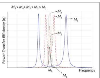
represents the device to be powered or charged. The η vs fre-quency response exhibits different characteristics depending on whether the coupled loops operate either one these re-gimes. A typical η response of two coupled identical resonant loops, for various (Ms), is shown in Figure 3.
Each loop is resonant at ω0 in order to achieve a maximum ef-ficiency value. As seen in Figure 3, when Ms are lower than M3 (e.g M1, M2), peak efficiency is observed at ω0 and increases with increasing M. This is the typical efficiency characteristic of cou-pled resonant loops operating at the weakly coucou-pled regime. When Ms are larger than M3 (e.g M4 , M5), two efficiency peaks are observed at two resonance frequencies of ωodd and ωeven, which are called the odd mode resonance frequency and the even mode resonance frequency, respectively. The efficiency is maximum at ωodd and ωeven and is independent of M. This is the typical efficiency response characteristic of coupled resonant loops operating in strongly coupled regime. The ωodd and ωeven get separated from the ω0 with increasing M. In other words, as M increases, coupled resonant loops get in to strongly coupled regime from the weakly coupled regime and ω0 is split into two more resonance frequencies of ωodd and ωeven in the strongly coupled regime (Figure 3).The M at which coupled resonant loops change their operation from weakly coupled regime to strongly coupled regime is called the critically coupled point (e.g M3 in Figure 3). Strongly coupled regime is very advanta-geous in wireless power transfer; because, M-independent efficiency means that one can transfer a constant power even if the distance between the loops varies. To realize that, one needs to set up a frequency-tuned system like those that have recently been proposed in several works [18-21]. However, the distance range over which efficiency is constant is limited to a critically coupling distance (dcritical). The efficiency response,
in particular the peak efficiency and the critically coupled dis-tance (dcritical), are dependent on the loop size and the source and load resistances.
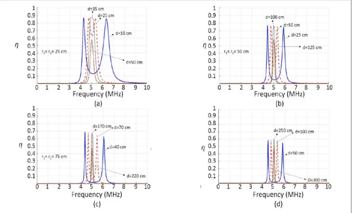
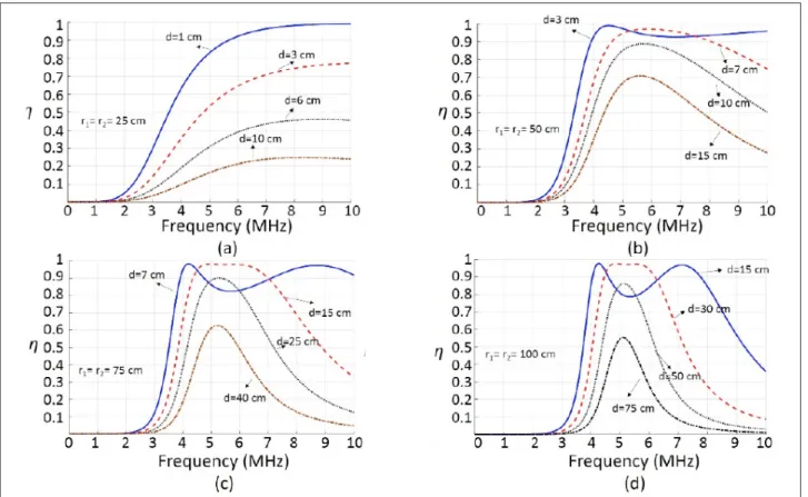
Figure 4 a-d, show four different graphs for coupled identical single turn (N=1) circular loops with a radius of 25 cm, 50 cm,
Figure 2. Equivalent circuit model with source and loads
con-nected, for simulating the power transfer efficiency
Figure 3. A typical η response of two coupled identical resonant
75 cm and 100 cm, respectively. The loops are resonant with series connected capacitances at 5 MHz. Each graph depicts a simulated efficiency (η) vs frequency data for various separa-tion distances (d) between the loops. Here the simulasepara-tions are performed for the same load and source resistance values of 2 Ω (Rs= RL = 2 Ω).
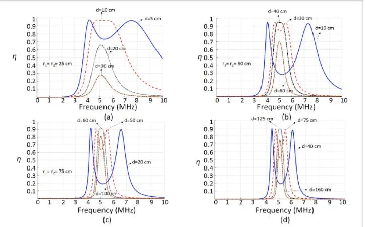
Figure 5-7, show similar efficiency graphs for 10 Ω, 25 Ω and 50 Ω source & load resistance values, respectively.
In Figure 4, where source and load resistances are 2 Ω, peak efficiencies at strongly coupled regime are 86 %, 77 %, 68 % and 59 %, for loops with radius of 25 cm, 50 cm, 75 cm and 100 cm, respectively. It can clearly be seen that the peak efficiency is significantly reduced with increasing loop sizes. The critical coupling distance, on the other hand, increases from 35 cm to 250 cm as loop size increases from 25 cm to 100 cm. Such be-haviour of peak efficiency and critical coupling distance can be explained as follows:
• As the size of the loops increases, larger M values are ob-tained for the same loop separations; therefore, loops can stay in strongly coupled regime for larger separations be-tween the loops (dcritical increases). This is advantageous be-cause one can operate with almost distance-independent efficiency in larger loop separations. However, due to fre-quency splitting phenomena in strongly coupled
opera-tion, one needs a frequency tuned wireless power transfer system.
• As the size of the loops increases, the radiation loss resis-tance (Rrad) and conductor loss resistance (Rc) increases; hence the peak efficiency decreases due to these larger loss resistances.
It should be remembered that the efficiency plots in Figure 4 are for source and load resistances of 2 Ω. Figure 5-7, show effi-ciency graphs for source & load resistances (RS and RL) of 10 Ω, 25 Ω and 50 Ω, respectively. To analyze the effect of RS and RL
on peak efficiency and critical coupling distance, one can focus on the efficiency response for the same loop size in each figure. For example, in Figure 4 d, Figure 5 d, Figure 6 d and Figure 7 d, where loop radius is 100 cm, it can clearly be seen that the peak efficiency increases as RS and RL increase. However, the critical coupling distance decreases with increasing RS and RL.
A major conclusion from these simulation results is that one can increase critical coupling distance by either increasing loop size or by decreasing RS and RL values. In either case, any increase in critical coupling distance would be at the cost of re-duced peak efficiency. Therefore, loop sizes and input & output matching circuits should be carefully designed considering this tradeoff. Figure 8 a, b show peak efficiency (ηmax) and critical
coupling distance (dcritical) as a function of loop radius for various RS and RL.
Figure 5. a-d. Efficiency (η) vs Frequency graphs for circular loops of radius of 25 cm (a); 50 cm (b); 75 cm (c) and 100 cm (d) RS=RL= 10 Ω
Model Verification through Measurements of Coupled Circular Loops
In the previous section, a significant analysis was performed using circuit model and geometry-dependent analytic equa-tions. In this section, we fabricated two multiturn circular loops to verify the accuracy of the model utilized in simulations. The loops are fabricated by winding solid copper wires on an ep-oxyglass. The radius of the loops is 25 cm and the number of turns is 5. Each loop’s self-inductance L is measured using a RLC meter. Then each loop is resonated out using a series
con-nected capacitor at 1 MHz. Simulations were performed at 5 MHz. Here, we intentionally resonated out the loops at 1 MHz to reduce the inter-winding parasitic capacitance in multiturn loops. Table 1 shows the theoretical and measured self-induc-tance values of each 5 turn loops. The required values of series connected capacitors to form a resonance at 1 MHz are also shown in Table 1.
The S-parameters of magnetically coupled resonant loops are measured from 100 kHz to 5 MHz using Rohde & Schwarz FSH8 Spectrum +Network analyzer as shown in Figure 9.
Figure 7. a-d. Efficiency (η) vs Frequency graphs for circular loops of radius of 25 cm (a); 50 cm (b); 75 cm (c) and 100 cm (d) RS=RL= 50 Ω
The efficiency is extracted from the measured S-parameters by taking the square of S21 as follows:
η = S
212(7)
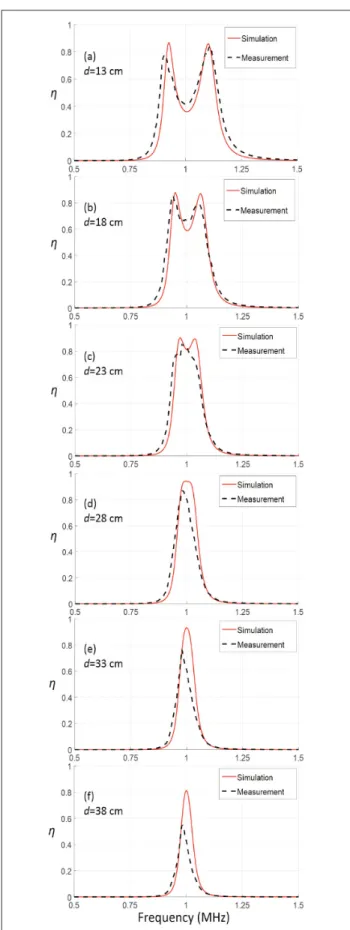
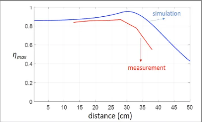
Measured efficiency as a function of frequency for various loop separations are shown in Figure 10 a-f. RS and RL resistances in these measurements are 20 Ω and 10 Ω, respectively. Fig-ure 11 shows the plot of peak efficiency vs distance for both simulation and measurement results. As seen in Figure 10, 11; the measurement results agree well with the simulation results specifically in strongly coupled regime. The critical coupling distance dcritical is approximately 30 cm. The difference between the simulations and the measurement results could be at-tributed to some losses that are not considered in the model, such as the proximity effect of multi-turn loops and the loss of series connected resonance capacitors.
Conclusion
In this paper we have presented a circuit model based analy-sis of magnetically coupled resonant loops for use in wireless
Table 1. Theoretical and Measured Values of Self Inductances for Fabricated Loops
Theoretical Measured
Loop 1 L1 = 35.8 μ H C1 = 707 pF L1 = 29.1 μ H C1 = 875 pF Loop 2 L2 = 35.8 μ H C2 = 707 pF L2 = 28.8 μ H C2 = 875 pF
Figure 9. S-parameter measurement setup for magnetically
cou-pled loops
Figure 10. Comparison of simulation and measurement results for
power transfer systems. The model employs analytical equa-tions for loop’s inductive parameters such as self and mutual inductances, and loss parameters such as conductor and radi-ation loss resistances. Hence overall power transfer efficiency was accurately predicted using this model. A thorough anal-ysis was also performed showing how the peak efficiency and the critical coupling distance changes as loop size and load & source resistances vary. The trade off between peak efficiency and critical coupling distance is discussed in detail. To validate the model’s accuracy, two 5 turn identical loops are fabricated and their efficiencies are measured. Future work would be to employ the proximity loss effects into the model and to con-duct a study on reducing the electrical losses in the loops.
Peer-review: Externally peer-reviewed.
Conflict of Interest: The authors have no conflicts of interest to declare. Financial Disclosure: This research is supported by The Scientific and
Technical Research Council of Turkey (TUBITAK-EEEAG-115E001).
Acknowledgements: The authors would like to thank to EMC
Elec-tronics Company, specifically Refik Alemdar and Dr. Bektas Colak from Gebze, Turkey, for letting us compare our measurement results using their instruments.
References
1. A. Kurs, A. Karalis, R. Moffatt, J. D. Joannopoulos, P. Fisher, M. Solja-cic, “Wireless power transfer via strongly coupled magnetic reso-nances”, Science, vol. 317, no. 5834 pp. 83-86, 2007.
2. F. Zhang, S. A. Hackworth, W. Fu, C. Li, Z. Mao, M. Sun, “Relay effect of wireless power transfer using strongly coupled magnetic resonances”,
IEEE Transactions on Magnetics, vol. 47, no. 5, pp. 1478-1481, 2011.
3. A. Karalis, J. D. Joannopoulos, M. Soljačić, “Efficient wireless non-radiative mid-range energy transfer”, Annals of Physics, vol. 323, no. 1, pp. 34-48, 2008.
4. E. M. Thomas, J. D. Heebl, C. Pfeiffer, A. Grbic, “A power link study of wireless non-radiative power transfer systems using resonant shielded loops”, IEEE Transactions on Circuits and Systems I: Regular
Papers, vol. 59, no. 9 pp. 2125-2136, 2012.
5. J. D. Heebl, E. M. Thomas, R. P. Penno, A. Grbic, “Comprehensive anal-ysis and measurement of frequency-tuned and impedance-tuned wireless non-radiative power-transfer systems”, IEEE Antennas and
Propagation Magazine, vol. 56, no. 5, pp. 131-148, 2014.
6. C. G. Pope, “Coupled Mode Theory and Wireless Energy Transfer”, 2012. 7. J. Huh, W. Lee, S. Choi, G. H. Cho, C. T. Rim, “Explicit static circuit
model of coupled magnetic resonance system”, 8th International
Conference on Power Electronics - ECCE Asia, 2011.
8. A. Robichaud, M. Boudreault, D. Deslandes, “Theoretical Analysis of Resonant Wireless Power Transmission Links Composed of Elec-trically Small Loops”, PIER, vol. 143, pp. 485-501, 2013.
9. C. J. Chen, T. H. Chu, C. L. Lin, Z. C. Jou, “A study of loosely coupled loops for wireless power transfer”, IEEE Transactions on Circuits and
Systems II: Express Briefs, vol. 57, no. 7, pp. 536-540, 2010.
10. S. H. Lee, R. D. Lorenz. “Development and validation of model for 95%-efficiency 220-W wireless power transfer over a 30-cm air gap”, IEEE
Transactions on Industry Applications, vol. 47, no.6, pp. 2495-2504, 2011.
11. S. H. Lee, R. D. Lorenz. “A design methodology for multi-kW, large air-gap, MHz frequency, wireless power transfer systems”, Energy Conversion Congress and Exposition (ECCE), 2011.
12. T. Imura, H. Okabe, T. Uchida, Y. Hori, “Study on open and short end helical antennas with capacitor in series of wireless power trans-fer using magnetic resonant couplings”, 35th Annual Conference of
IEEE Industrial Electronics, 2009.
13. J. Kim, J. Jeong, “Range-adaptive wireless power transfer using multiloop and tunable matching techniques”, IEEE Transactions on
Industrial Electronics, vol. 62, no. 10, pp. 6233-6241, 2015.
14. X. Wei, Z. Wang, H. Dai, “A critical review of wireless power transfer via strongly coupled magnetic resonances”, Energies, vol. 7, no. 7 pp. 4316-4341, 2014.
15. B. J. Jang, S. Lee, H. Yoon, “HF-band wireless power transfer sys-tem: Concept, issues, and design”, Progress in Electromagnetics
Re-search, vol. 124, pp. 211-231, 2012.
16. C. A. Balanis, Antenna theory: analysis and design, John Wiley & Sons, 2016.
17. D. M. Pozar, Microwave engineering, John Wiley & Sons, 2009. 18. Y. Gao, C. Zhou, J. Zhou, X. Huang and D. Yu, “Automatic Frequency
Tuning with Power-Level Tracking System for Wireless Charging of Electric Vehicles”, IEEE Vehicle Power and Propulsion Conference (VPPC), 2016.
19. D.P. Kar, P.P. Nayak, S. Bhuyan, S.K. Panda, “Automatic frequency tuning wireless charging system for enhancement of efficiency,” in Electronics Letters, vol. 50, pp. 1868-1870, November 2014. 20. S. A. Sis, S. Bicakci, “A resonance frequency tracker and source
frequen-cy tuner for inductively coupled wireless power transfer systems”, 46th
European Microwave Conference (EuMC), 2016, pp. 751-754. 21. S. Bıçakçı, S. A. Sis, “Design Of A Resonance Frequency Tracking System
For Rf Applications”, GU J Sci, vol. 5, no. 2, pp. 211-221, 2017. Seyit Ahmet Sis (S’07) received the B.S. degree in electronics engineering from the Gebze Institute of Technology, Kocaeli, Turkey, in 2005, the M.S. degree in electrical engineering from Syracuse University, Syracuse, NY, in 2008, and the Ph.D. degree from The University of Michigan at Ann Arbor, in 2014. From August 2005 to February 2007, he was with the Scientific and Technical Research Council of Turkey (TUBITAK-UEKAE). He is currently Assistant Professor of Electrical-Electronics Engineering Department at the Balikesir University, Balikesir, Turkey. His cur-rent research interests include wireless power transfer systems, high frequency passive circuits and amplifier design switchable and tunable microwave components.
Figure 10. Peak efficiency ηmax vs distance for simulation and