Journal of istanbul Kültür University 2006/4 pp.55-64
DYNAMICS OF TWO COUPLED, NONLiNEAR, AUTONOMOUS 4th
ORDER CIRCUITS
Maria S. PAPADOPOULOU, Ioannis M. KYPRIANIDISi, Ioannis N. STOUBOULOS'
Abstract
In this paper we have studied the case of chaotic synchronization of two identical, mutually coupled, non linear, 4th order autonomous electric circuits. Each circuit contains one linear negative conductance G and one non linear resistür RNwith a symmetrical piecewise-linear v-i characteristic. Using the capacitances Ci andCias the control parameters, we have observed the transition from periodic states to chaotic ones and vise versa, as well as crisis phenomena. We have established the mutual coupling via a variable resistür Rx.We have observed that synchronization is possible as the resistance of the coupling element is varied.
Keywords: Chaotic synchronization, Autonomous circuit, Control parameter, Crisis, Mutual coupling.
i.
IntroductionSince the discovery by Pecora and Carroll [1], that chaotic systems can be synchronized, the topic of synchronization of coupled chaotic circuits and systems has been studied intensely [2] and some interesting applications, as in broadband communications systems, have come out of this research [3-5]. Generally, there are two methods of chaos synchronization available in the literature. In the first method, due to Pecora and Carroll [1], a stable subsystem of a chaotic system could be synchronized with a separate chaotic system, under certain suitable conditions. The second method to achieve chaos synchronization between two identical nonlinear systems is due to the effect of resistive coupling without requiring to construct any stable subsystem [6-8]. According to Carroll and Pecora [9], periodically forced synchronized chaotic circuits are much more noise-resistant than autonomous synchronized chaotic circuits.
in this paper we have studied the case of two identical fourth-order autonomous nonlinear electric circuits (Figure 1) with two active elements, one linear negative conductance and one nonlinear resistor with a symmetrical piecewise line ar v - i characteristic (Figure 2). Using the capacitances Ci and Cz as the control parameters, we
have observed areverse period-doubling sequence, as well as a crisis phenomenon, when the spiral attractor suddenly widens to a double-scroll attractor [10].
2. The Non Linear 4th Order Circuit
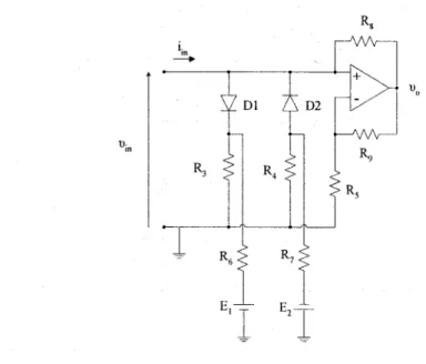
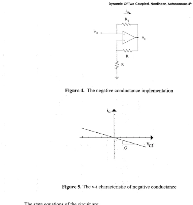
The circuit, we have studied, is shown in Figure 1 and has two active elements, a nonlinear resistor RN and a line ar negative conductance G, which were implemented using the circuits shown in Figures 3 and 4 respectively. The v-i characteristic of the negative conductance G is shown in Figure 5.
Maria S. Popodopoulou, loannis M. Kyprianidis, loannis N. Stouboulos
A
B
Figure 1. The 4th order autonomous circuit B
Figure 2. The piece-wise linear and symmetrical v-i characteristic of nonlInear resistür RN
U·m
i
m--Di D2
Dynomic Of Two Coupled, Noniineor, Autonomous 4thOrder Circuits
1· ~
R R
Figure 4. The negative conductance implementation
Figure 5. The v-i characteristic of negative conductance
The state equations of the circuit are:
dUci =~'{iL1
-f(uc\)}
dt Ci (2.1)
(2.2)
(2.3)
Morio S. Popodopoulou. loonnis M. Kyprionidis. loonnis N. Slouboulos
where:
The value s of circuit's parameters are: Li=1O.2mH, L2=21.5mH, R1=2.02KQ,
R2=108Q, G=-O.5mS, Ga=-O.833mS, Gb=-O.5l4mS, Gc=2.9mS, Elp=1.46V and E2p=10.lV.
3. Mutual CoupIing of Two Identical NonIinear 4th Order Circuits
If two identical circuits are resistively coupled, complex dynamics can be observed, as well as chaotic synchronization, as the coupling parameter Rx is varied. The two circuits can be either vci-coupled orvcrcoupled. The system of the two identical 4th order nonlinear circuits vci-coupled via the linear resistür Rx is shown in Figure 6. The state equations of the coupled system are:
duCJI
1
{u -u }ili=- Ci' CIIRx Cl2 iLlI +f(uCIl) . (3.1)
duC21 1
ili =
-C·{G
2 ·UC21+iLlI +iLZi} (3.2) diLlI1
ili=L'{UC21-iLllRI-ucIJ
I
(3.3) diLZL 1dt =L'{uC212 -iL21R2} (3.4)
diLl2 1
dt=~'{UC22 -iLl2R! -uCl2} (3.7) diLZ2 1
Dynamic Of Two Coupled, Noniinecr, Autonomous 4thOrder Circuits
4. Experimental Results
4.1Dynamic behavior of the 4tb order nonlinear dreuit
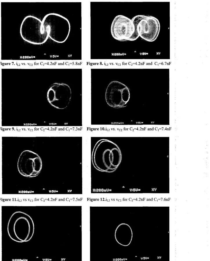
The chaotic attractors of the two circuits, when theyare uncoupled, are shown in the following figures. in Figures 7-14 we can see the portraits x-y ~ iL2-VC2 for C2=4.2nF. in Figure 7, we see iL2vs. VC2 for Ci=5.8nP and we observe that the system is in periodic state.
in Figure 8, the iL2vs. VC2 diagram is presented for Ci=6.7nF and we observe the
double-scroll attractor. in Figures 9-11, the phase portraits are shown for Ci=7.3nF, Ci=7.4nP and
Ci=7.5nF respectively, and we observe the chaotic attractors. For Ci=7.6nP, Ci=9.2nP and
Ci=9.6nF (Figures 12-14 respective1y) the system is in periodic states with periods 4-2-1, respectively.
Maria S. Papadopoulou, loannis M. Kyprianidis, loannis N. Stouboulos
Figure 7.ILZvs, Vci for Ci=4.2nP and Ci=5,8nP Figure 8.ILZvs. Vci for Ci=4.2nP and Ci=6.7nP
Figure 9.ILZvs. Vci for Ci=4.2nP and Ci=7.3nP Figure lO.ILZvs. Vci for Ci=4.2nP andCi=7.4nP
Dynamic Of Two Coupled. Noniinear. Aufonomous 4'" Order Circuits
CoupIing two identical 4lh order nonIinear circuits
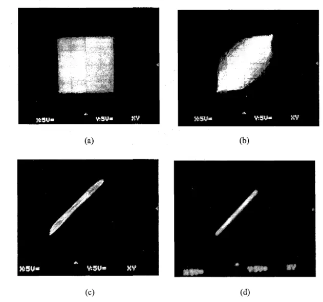
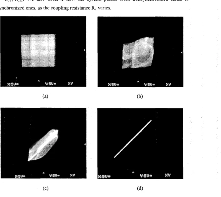
We have studied the possibility of chaotic synchronization when the initial conditions of the coupled circuits belong to the same basin of attraction. in Pigures 15(a)-(d) we can see the experimental results from the coupled system for C2=4.20nP, C1=6.7nP and various values of the coupling resistür Rx. The diagrams are x-y ~ VC21-VC22. We observe
how the system passes from nonsynchronized states to synchronized ones, depending on the coupling resistance Rx.
(a)
(c)
(b)
(d)
Figure 15. VC2I vs. Vcn for Ci=6.7nP, C2=4.2nP and (a) Rx= 00(b) Rx=llKO (c) Rx= 1.1KO (d) Rx=990
Maria S. Papadopoulou, loannis M. Kyprianidis, loannis N. Stouboulos
In Pigures 16(a)-(d) we can see the experimental results from the coupled system for C2=4.20nP, Ci=7.3nP and various values of the coupIing resistür Rx. The diagrams are x-y -;. VC2l-VC22. We also observe how the system passes from nonsynchronized states to synchronized ones, as the coupIing resistance Rx varies.
(a)
(c)
(b)
(d)
Figure 16.VC2l vs.VC22 for Ci=7.3nP,C2=4.2nP and (a) Rx = ao(b) Rx= 30Kü (c) Rx= 8Kn
(d) Rx=lKü
5. Conclusion
in this paper we have implemented two identical 4th order circuits and we have shown that chaotic synchronization is possible experimentally.
Dynamic Of Two Coupled, Noniinear, Autonomous 41hOrd er Circuits
Using the capacitances Ci and Cz as the control parameters, we have observed the transition from periodic states to chaotic ones and vise versa, as well as crisis phenomena, when the spiral attractor suddenly widens to a double-scroll attractor (Figures 9 and 10).
Furthermore, we have seen the chaotic synchronization of two identical circuits, which are mutually coupled via a Iinear resistor Rx, when the initials conditions of the coupled circuits belong to the same basin of attraction, Experimental results have shown that chaotic synchronization is possible in the case ofvcz-coupIing. We have observed that for Cz=4.2nf and Ci=6.7nF chaotic synchronization is possible for coupIing parameter E=R1/Rx>20.4, while for Cz=4.2nf and Ci=7.3nF is possib1e for E>2.02. SO we conclude that the capacitance Ci and the coupIing parameter E are conversely proportiona1 quantities.
Acknowledgments
This work has been supported by the re search program "EPEAEK
II,
PYTHAGORAS II", code number 80831, ofthe Greek Ministry of Education and E.U.References
[1] Pecora, L. M., and Carroll,T L., (1990), "Synchronization in chaotic systems",Physical Review Letters, Vol. 64, No.8, pp. 821-824.
[2] Wu, C. W., (2002), Synchronization in Coupled Chaotic Circuits and Systems, Singapore, World Scientific, [3] Cuomo, K. M., and Oppenheim, A. V., (1993), "Circuit implementation of synchronized chaos with
applications to communications",Physical Review Letters, Vol.71, No.1, pp. 65-68.
[4] Kocarev, L., and Parlitz, u.,(1995), "General approach for chaotic synehronization with applications to communieations",Physical Review Letters, Vo1.74,No.25,pp. 5028-5031.
[5] Kolumban, G., Kennedy, M. P., and Chua, L. O., (1997), "The role of synehronization in digital communications using chaos - part i: Fundamentals of digital communications", IEEE Transactions Circuits Systems-I, Vo1.44,pp. 927-936.
[6] Murali, K., and Lakshmanan, M., (1994), "Drive-response seenario of ehaos synehronization in identieal nonlinear systems",Physical Review E,Vo1.49,No.6, pp. 4882-4885.
[7] Kapitaniak, T., Chua L. O., and Zhong, G.-Q, (1994), "Experimental synchronization of chaos using continuous control",International Journal ofBifurcation and Chaos, YolA, No.2, pp. 483-488.
[8] Murali, K., Lakshmanan, M., and Chua, L. O., (1995), "Controlling and synehronization of ehaos in the simplest dissipative nonautonomous circuit",International Journal of Bifurcation and Chaos, Vo1.5, No.2, pp. 563-571.
[9] CarolI, T L., and Peeora, L. M., (1993), "Synchronizing nonautonomous chaotie eireuits", IEEE Transactions Circuits Systems-II, Vo1.40,pp. 646-650.
[lO] Kyprianidis, i. M., Stouboulos, i. N., Haralabidis, P., and Bountis, T, (2000), "Antimonotonieity and ehaotic dynamies in a fourth-order autonomous nonlinear electric cireuit",International Journal of Bifurcation and Chaos, Vo1.10,No.8, pp. 1903-1915.
Maria S. Papadopoulou, loannis M. Kyprianidis, loannis N. Stouboulos
List of Figures:
Figure
i.
The4th order autonomous circuitFigure 2. The piece-wise linear and symmetrica! v-i characteristic ofnonlinear resistor RN
Figure 3. The nonlinear resistor RN implementation Figure 4. The negative conductance imp!ementation
Figure 5. The v-i characteristic of negative conductance
Figure 6. The vci-coup!ed system of the two identica! 4thorder nonlinear circuits
Figure 7.iL2vs.Vcifor Ci=4.2nF and Ci=5.8nF
Figure 8.iL2vs.Vcifor Ci=4.2nF and Ci=6.7nF
Figure 9.iLivs.Vcifor Ci=4.2nF and Ci=7.3nF
Figure 10.iL2vs.Vcifor Ci=4.2nF and Ci=7.4nF
Figure 11.iLi vs,VC2 for Ci=4.2nF and Ci=7.5nF
Figure 12.iL2vs.Vcifor Ci=4.2nF and Ci=7.6nF
Figure 13.iL2vs.VC2 for Ci=4.2uF and Ci=9.2nF
Figure 14.iL2vs,Vcifor Ci=4.2uF and Ci=9.6nF
Figure 15.Vciivs.VC22 forCi=6.7nF,Ci=4.2nF and (a) Rx=oo(b) Rx=llKn (c) Rx=l.lKn (d) Rx=99n