ONE-POT SYNTHESIS OF HYBRID
CORE-SHELL NANOPARTICLES FOR
ANTIBACTERIAL PHOTODYNAMIC
THERAPY
a thesis submitted to
the graduate school of engineering and science
of bilkent university
in partial fulfillment of the requirements for
the degree of
master of science
in
materials science and nanotechnology
By
Seyed Ehsan Hadi
July 2019
ONE-POT SYNTHESIS OF HYBRID CORE-SHELL NANOPARTI-CLES FOR ANTIBACTERIAL PHOTODYNAMIC THERAPY By Seyed Ehsan Hadi
July 2019
We certify that we have read this thesis and that in our opinion it is fully adequate, in scope and in quality, as a thesis for the degree of Master of Science.
D¨on¨u¸s TUNCEL(Advisor)
Hilmi Volkan DEM˙IR
Talha ERDEM
Approved for the Graduate School of Engineering and Science:
ABSTRACT
ONE-POT
SYNTHESIS OF HYBRID CORE-SHELL
NANOPARTICLES
FOR ANTIBACTERIAL
PHOTODYNAMIC
THERAPY
Seyed Ehsan Hadi
M.S. in Materials Science and Nanotechnology Advisor: D¨on¨u¸s TUNCEL
July 2019
Multidrug resistance (MDR) in Escherichia coli (E. coli) has become a worrying issue that is not only increasingly observed in humans but also is widespread in veterinary medicine worldwide. Therefore, developing new and effective alter-natives to conventional antibiotics has become an imperative need. The idea of using photodynamic therapy (PDT) for bacterial eradication is a solution for the cases that the bacteria are resisting to conventional antibiotics. Although in these cases, PDT can be an option, PDT-killing efficiency might still not be sufficient, and some enhancements are necessary. Metal-enhanced singlet oxygen generation (ME1O2) is one of the ways to enhance the PDT-killing efficiency of the E. coli.
Hybrid core-shell structures can serve conveniently for this purpose. These struc-tures can combine the flexible and tailorable features of polymers (shell) with the photophysical properties of plasmonic metals (core). In this work, using gold as a core and conjugated oligomer as a shell produced a novel hybrid core-shell nanoparticles which can enhance the singlet oxygen generation capacity and sub-sequently, improve the PDT-killing efficiency of the E. coli. In this structure, the shell is responsible for the spontaneous reduction of gold ions, forming gold nanoparticles and protecting them from the aggregation. With further investiga-tion and optimization, the hybrid core-shell nanoparticles with the help of ME1O
2
successfully improved the killing efficiency of E. coli bacteria by 40%.
Keywords: core-shell nanoparticle, antibacterial photodynamic therapy, metal-enhanced singlet oxygen generation, ROS, E. coli, conjugated oligomer, gold nanoparticle.
¨
OZET
ANTIBAKTERIYEL
FOTODINAMIK TEDAVIYE
Y
¨ONELIK HIBRIT C¸ EKIRDEK-KABUK
NANOPARC
¸
ACIKLARININ TEK ADIMDA SENTEZI
Seyed Ehsan Hadi
Malzeme Bilimi ve Nanoteknoloji, Y¨uksek Lisans Tez Danı¸smanı: D¨onu¨s¸ TUNCEL
Temmuz 2019
E. coli bakterisindeki ¸coklu ila¸c direnci (MDR) insanlarda oldu˘gu kadar hay-vanlarda da giderek yaygınla¸san endi¸se verici bir sorun haline gelmi¸stir. Bu ne-denle geleneksel antibiyotiklere alternatif etkili ila¸clar geli¸stirmek zorunlu hale gelmi¸stir. Bakterilerin geleneksel antiboyatiklere kar¸sı diren¸c g¨osterdi˘gi durum-larda fotodinamik tedaviden (PDT) yararlanma du¨s¸¨uncesi bakterileri yok etmek i¸cin bir ¸c¨oz¨umd¨ur. PDT bu durumlarda bir se¸cenek olmasına ra˘gmen, bakter-ileri yok etme verimlili˘gi ¸co˘gu zaman yeterli de˘gildir ve bir takım iyile¸stirmeler yapmak gerekmektedir. Metalle artırılmıs¸ singlet oksijen (ME1O
2) ¨uretimi PDT ile E. coli
bakterisini ¨old¨urme verimlili˘gini artırma yollarından biridir. Bu t¨ur yapılar, polimerlerin (kabuk) esnek ve ayarlanabilir ¨ozelliklerini plasmonik met-allerin (¸cekirdek) optik, elektronik ve fotofiziksel ¨ozellikleriyle bir araya getire-bilir. Bu ¸calı¸smada, altını ¸cekirdek olarak kullanıp konjuge oligomeri kabuk olarak kullanarak, y¨uksek singlet oksijen ¨uretim verimine sahip olan ve E. coli bakterisini ¨
old¨urme verimi artırılmıs¸ hibrit ¸cekirdek-kabuk nanopar¸cacıkları sen-tezlenmi¸stir. Bu yapıda kabuk, altın iyonlarının spontane indirgenerek altın nanopar¸cacıkları olu¸sturmasından ve agregasyondan korunmasından sorumludur. Detaylı ara¸stırma ve iyile¸stirmelerle, hibrit ¸cekirdek-kabuk nanopar¸cacıkları, ME1O
2’nin
de yardımıyla, E. Coli ¨old¨urme verimini %40 artırmı¸stır.
Anahtar s¨ozc¨ukler: ¸cekirdek-kabuk nanopar¸cacı˘gı, antibakteriyel fotodinamik te-davi, metalle iyile¸stirilmi¸s singlet oksijen ¨uretimi, reaktif oksijen t¨urleri, E. coli,
Acknowledgement
First of all, I would express my sincere gratitude to my advisor, Prof. D¨on¨u¸s Tun-cel, for the continuous support of my master’s study and research. Her guidance helped me to accomplish my thesis, develop my teamwork ability, and improve my academic personality.
I would like to thank the examining committee members, Prof. Hilmi Volkan Demir, and Prof. Talha Erdem, for their encouragement and insightful comments. I want to extend my sincerest thanks to all faculty members and staff of the Bilkent University National Nanotechnology Research Center (UNAM) who have contributed to my scientific knowledge. I also thank Bilkent University, UNAM, and T ¨UB˙ITAK for financial support throughout my master’s studies.
I need to express my deepest gratitude to Dr. Yogesh Kumar, Dr. Ahmet Ko¸c, Dr. Rehan Khan, Dr. Aysan Khaligh Vazirabadi, and Dr. Timu¸cin Balkan for their guidance and support and special thanks to Melis ¨Ozkan for her tremendous help.
My sincere thanks go to my friend Abbas Khodadadi, for his support. Also members of the Demir research group and the Elb¨uken research group, especially Farzan Shabani, Nima Taghipour, Ali Kalantaifard, and Azimet Akber Karluk and many thanks to all friends and individuals who have directly or indirectly contributed to this work.
Finally, I have to offer my most special thanks to my family, especially Sol, for their support and care.
Contents
1 Introduction and Background 1
1.1 Nanoscience and Nanotechnology . . . 1
1.1.1 Properties . . . 2 1.1.2 Characterization . . . 3 1.1.3 Applications . . . 4 1.2 Conjugated Polymers . . . 5 1.2.1 Properties . . . 5 1.2.2 Application . . . 8 1.3 Plasmonic Nanoparticles . . . 9
1.3.1 Properties and Applications . . . 9
1.3.2 Gold Nanoparticles . . . 10
1.4 Core-Shell Nanostructures . . . 13
CONTENTS vii 1.4.2 Properties . . . 14 1.4.3 Applications . . . 15 1.5 Colloidal Systems . . . 16 1.6 Photothermal Therapy . . . 19 1.7 Photodynamic Therapy . . . 21
1.7.1 Metal-Enhanced Singlet Oxygen Generation (ME1O 2) . . . 24
1.8 E. coli bacteria . . . 26
1.9 Previous Works with Red-Emitting Conjugated Oligomer . . . 27
2 Introduction to measurement techniques 28 2.1 Dynamic Light Scattering and Zeta Potential . . . 28
2.2 Ultraviolet-visible Spectroscopy . . . 32
2.3 X-ray Diffraction . . . 34
2.4 Fluorescence Spectroscopy . . . 36
2.5 Time-resolved Fluorescence Lifetime . . . 38
2.6 X-ray Photoelectron Spectroscopy . . . 39
2.7 Transmission Electron Microscopy . . . 42
2.8 Scanning Electron Microscopy . . . 44
2.9 Critical Point Dryer . . . 46
CONTENTS viii
2.11 Fourier-transform Infrared Spectroscopy . . . 48
3 Experimental 50 3.1 Materials . . . 50
3.2 Synthesis . . . 50
3.2.1 Synthesis of Red-Emitting Oligomer . . . 50
3.2.2 Dispersion of Conjugated Oligomer Nanoparticles in Water 53 3.2.3 Synthesis of Hybrid Core-Shell Nanoparticles . . . 54
3.3 Antibacterial Assays . . . 55
3.3.1 Preparation of the Bacterial Solution and Minimum In-hibitory Concentration (MIC Assay) . . . 55
3.3.2 Biocidal activities of COL and Au@COL nanoparticles to-ward E. Coli . . . 56
3.3.3 Preparing the bacteria for imaging . . . 56
3.3.4 Zeta Potential Measurements . . . 57
3.3.5 ROS Measurements . . . 57
3.4 Instrumentation . . . 58
3.4.1 Transmission Electron Microscopy . . . 58
3.4.2 Scanning Electron Microscopy . . . 58
CONTENTS ix
3.4.5 Time-Resolved Fluorescence Spectroscopy . . . 59
3.4.6 X-Ray Powder Diffraction . . . 59
3.4.7 X-Ray Photoelectron Spectroscopy . . . 59
3.4.8 Dynamic Light Scattering and Zeta Potential . . . 60
3.4.9 Critical Point Dryer . . . 60
3.4.10 Microplate reader . . . 60
3.4.11 FT-IR Spectroscopy . . . 61
4 Results and Discussion 62 4.1 Aim of the Study . . . 63
4.2 Characterization . . . 64
4.2.1 Characterization of Red-Emitting Conjugated Oligomer . . 64
4.2.2 Characterization of Water-dispersed Conjugated Oligomer Nanoparticles . . . 68
4.2.3 Characterization of Water-dispersed Au@COL Nanoparticles 74 4.3 Interpretation of Characterization Data . . . 83
4.3.1 Optical properties . . . 84
4.3.2 Structural Analyses . . . 87
4.3.3 Morphology, Size, and Surface Properties . . . 91
4.3.4 Stability of the Au@COL nanoparticles aqueous solution over the time . . . 92
CONTENTS x
4.4 Application of Au@COL Nanoparticles . . . 93 4.4.1 Investigation of PDT-killing of E. coli . . . 93
5 Conclusion 103
List of Figures
1.1 Plot of the number of articles published on “nano” since 1992. . . 2
1.2 Molecular structures of typical conjugated polymers. . . 5
1.3 Band formation from molecular repeat unit to π-conjugated polymer. 6 1.4 Jablonski diagram demonstrating fluorescence and competing pathways for molecular relaxation from an excited state. . . 7
1.5 Effective parameters on the properties of CSNs. . . 15
1.6 Applications of CSNs. . . 16
1.7 Electrostatic stabilization of colloids. . . 18
1.8 Steric stabilization of colloids. . . 18
1.9 Scheme of PTT-Killing of E. coli bacteria. . . 20
1.10 Dissipation of energy through plasmon-mediated transformation mechanisms caused by SPR. . . 20
1.11 Jablonski diagram of small molecule PS for generation of 1O 2. . . 22
1.12 Jablonski diagram of conjugated polymer PS for generation of 1O 2. 22
LIST OF FIGURES xii
1.13 A simplified scheme of the mechanism of PDT-induced tumor
de-struction. . . 23
1.14 Modified Jablonski diagram of the photosensitizer and metal-enhanced singlet oxygen generation. . . 25
1.15 The expected performance of Au@COL and COL nanoparticles in the singlet oxygen generation. . . 25
2.1 Scheme of working principle of DLS. . . 28
2.2 The Illustration of zeta potential. . . 32
2.3 XRD pattern of a semi-crystalline material. . . 35
2.4 Schematic diagram of the main components of TEM. . . 43
2.5 Schematic diagram of the main components of SEM. . . 45
3.1 A simplified scheme of the synthesis of the red-emitting oligomer. 51 4.1 FT-IR spectrum of COL. . . 64
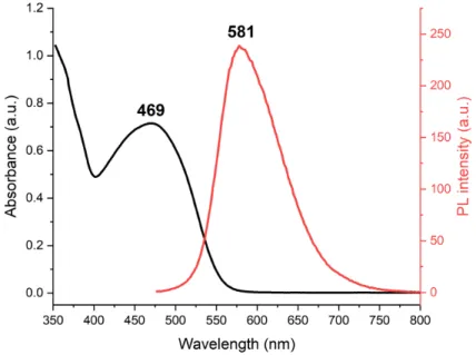
4.2 UV-Vis absorbance and fluorescence spectra of COL dissolved in THF. . . 65
4.3 Photoluminescence decay curves of COL dissolved in THF. . . 66
4.4 The XPS spectra of COL. . . 67
4.5 FT-IR spectrum of COL nanoparticles. . . 68
4.6 UV-Vis absorbance and fluorescence spectra of COL nanoparticles in water. . . 69
LIST OF FIGURES xiii
4.7 Photoluminescence decay curves of COL nanoparticles in water. . 69 4.8 DLS and zeta potential results of COL nanoparticles in water. . . 71 4.9 SEM images of water-dispersed COL nanoparticles. . . 72 4.10 The XPS spectra of water-dispersed COL nanoparticles. . . 73 4.11 The FT-IR spectrum of Au@COL nanoparticles. . . 74 4.12 UV-Vis absorbance and fluorescence spectra of Au@COL
nanopar-ticles in water. . . 75 4.13 Photoluminescence decay curves of Au@COL nanoparticles in water. 75 4.14 DLS and zeta potential measurements of Au@COL nanoparticles
in water. . . 77 4.15 TEM and HAADF-STEM images of Au@COL nanoparticles. . . . 78 4.16 EDX spectrum and HAADF-STEM images of Au@COL
nanopar-ticles. . . 79 4.17 The XPS spectra of water-dispersed Au@COL nanoparticles. . . . 81 4.18 X-ray diffraction pattern of Au@COL nanoparticles. . . 82 4.19 Suggested mechanism of reduction of gold ions and formation of
gold atoms. . . 83 4.20 The scheme of formation of gold nanoparticles inside the shell. . . 84 4.21 UV-Vis absorbance and fluorescence spectra of COL dissolved in
THF, COL nanoparticles in water, and Au@COL nanoparticles in water. . . 85
LIST OF FIGURES xiv
4.22 Photoluminescence decay curves of COL dissolved in THF, COL nanoparticles in water, and Au@COL nanoparticles in water. . . . 86 4.23 Quantum yield and fluorescence lifetime comparison bar charts of
all structures. . . 86 4.24 FT-IR spectra of COL, water-dispersed COL nanoparticles, and
water-dispersed Au@COL nanoparticles. . . 87 4.25 Comparison XPS diagram of COL dissolved in THF, COL
nanoparticles in water, and Au@COL nanoparticles in water. . . . 89 4.26 HRTEM image of a gold nanoparticle. . . 90 4.27 UV-Vis absorbance and fluorescence spectra of aged core-shell,
aged raspberry structure, and mixture of both structures. . . 92 4.28 The formation of DCF from DCFH in the presence of ROS such
as singlet oxygen. . . 94 4.29 PL spectra of DCF and time response curve of PL intensity of DCF
in the absence and the presence of (3.1 µM) COL nanoparticles under continuous white light irradiation. . . 95 4.30 PL spectra of DCF and time response curve of PL intensity of DCF
in the absence and the presence of (3.1 µM) Au@COL nanoparti-cles under continuous white light irradiation. . . 95 4.31 Time response curve of PL intensity of DCF in the presence of
Au@COL and COL nanoparticles. . . 96 4.32 MIC assay for different concentration of Au@COL and COL
nanoparticles under white light irradiation. . . 97 4.33 Biocidal activities of COL nanoparticles toward E. coli in the dark
LIST OF FIGURES xv
4.34 Biocidal activities of Au@COL nanoparticles toward E. coli in the dark and under light irradiation. . . 99 4.35 SEM images of E. coli in the dark and under light irradiation. . . 100 4.36 SEM images of E. coli treated with COL nanoparticles in the dark
and under light irradiation. . . 100 4.37 SEM images of E. coli treated with Au@COL nanoparticles in the
dark and under light irradiation. . . 101 4.38 Zeta potential comparison bar chart of E. coli upon the addition
of COL and Au@COL nanoparticles in the dark and under light irradiation. . . 102
List of Tables
2.1 Electron levels and corresponded degeneracy. . . 41
4.1 The overall optical properties of COL dissolved in THF, COL nanoparticles in water, and Au@COL nanoparticles in water. . . . 85 4.2 Summary of reported sizes and calculated zeta potentials. . . 91
Chapter 1
Introduction and Background
1.1
Nanoscience and Nanotechnology
Nanometer word consists of two words Nano (Nanos), which means “dwarf” in an-cient Greek and meter (Metron), which means “unit of measurement” in anan-cient Greek. It represents 10−9 m in International System of Units (Syst`eme inter-national d’unit´es, SI) [1]. Nanotechnology is a broad term referring to more of an approach to engineering than a science; however, it requires multidisciplinary knowledge in materials science, chemistry, physics, and biology. Nanotechnol-ogy is going to revolute these sciences affectedly [2]. NanotechnolNanotechnol-ogy has grown rapidly, and its bright future will attract many scholars [3]. According to Figure 1.1, the number of published articles on “nano” has increased from 6,075 in 2000 to 71,458 in 2018.
The 1925 Nobel Prize winner, Richard Adolf Zsigmondy, was the first who proposed the concept of the nanometer. Richard Feynman, the 1965 Nobel Prize winner, introduced the modern nanotechnology. The concept of manipulating matter at the atomic level was presented in 1959 in his lecture titled, “There is Plenty of Room at the Bottom”. In 1974, the “nanotechnology” term firstly used by a Japanese scientist, Norio Taniguchi, to define semiconductor processes that
Figure 1.1: Plot of the number of articles published on “nano” since 1992. Source: Web of Science, as of July 2019.
have been conducted on the order of a nanometer. The golden era for nanotech-nology began in the 1980s when Curl, Kroto, and Smalley discovered fullerenes. In the same decade, Eric Drexler used the term “nanotechnology” in his 1986 book titled, “Engines of Creation: The Coming Era of Nanotechnology” [4]. Looking at nature can be very helpful for a better understanding of the nanoworld. The diameter of a typical virus, an E. coli bacteria, and a hair are around 60-250 nm, 1,000-2,000 nm, and 50,000-100,000 nm, respectively. The smallest size that the naked eye can resolve is in the range of 55,000-75,000 nm depending on the conditions [5].
1.1.1
Properties
As we go to the nanoscale (within the range of 1-100 nm), the materials might show some extraordinary properties. All nanosystems obey the perfect law of nanomaterials. This law can be elaborated in a simple language: “Existence is perfect, and only the perfect can be existent.” But, what does it mean in reality? For answering this question, it is better to take a look at the magic number rule of nanocrystals. According to this rule, only the atom clusters with the number of atoms of 13, 55, 147 and others are considered stable [6]. The same scenario can
be seen in carbon atoms. The probability of the existence of carbon 60 (C60) and
carbon 70 (C70) in the fullerene structure is much higher than carbon 59 (C59)
and carbon 71 (C71) [5], [7]. In macroscopic materials, most of the parameters like
lattice constant, bond length, bond angle, the energy band, quantum state, and distribution function, are well determined. In nanoscale, however, most of the parameters may alter as the number of atoms changes, and this makes working with nanomaterials harder in comparison to macroscopic materials. This charac-teristic of nanomaterials also makes them incredibly tunable for getting new and different properties. Some examples will make previous statements more under-standable. Some metals will lose their thermal and electrical conductivity as they are reduced down to the nanoscale [8]. Fe-Co alloy nanoparticles show significant enhancement in electrocatalytic activity compared to bulk alloys [9]. One of the most interesting size-properties dependence of materials belongs to gold. The conventional melting point of gold is 1,064◦C. However, gold nanoparticle with a size of 10 nm has a melting point of 927 ◦C. If the size of the gold nanoparticles reduces to 2 nm, surprisingly, the melting point will be 327◦C [10]. Another crit-ical parameter in nanomaterials is the surface area to volume ratio of particles. As a rule, the higher the surface area to volume ratio, the higher the activity of the surface. This high activity can be explained with higher surface energy. High surface energy is not always a desirable characteristic. When the particles become smaller, the number of atoms at the surface in comparison to the internal atoms will be higher. This unbalanced distribution of atoms will result in high surface energy and eventually, instability. In order to confront instability and minimize the total energy of the system, the particles would like to combine with other particles and produce new particles with less surface area to volume ratio.
1.1.2
Characterization
Here is a concise explanation of some of the characterization techniques. More details regarding the characterization techniques can be found in chapter 2. Char-acterization is one of the most vital tasks when we deal with nanomaterials. As mentioned, some known macroscopic properties will not be valid in nanoscale,
and developing new methods to characterize nanomaterials is essential. Surface characterization, particle composition, crystallinity, size distribution, morphol-ogy, optical, electrical, mechanical, and other properties will be covered in a full characterization of nanomaterials. The most appealing characterization of nanomaterials is their morphology. Electronic microscopes and rarely optical mi-croscopes can be used for this purpose. Optical mimi-croscopes due to their working principle cannot resolve objects smaller than 200 nm [11], [12]. Electronic mi-croscopes, however, can resolve objects up to 4 angstroms (the size of an atom is in the range of 1 to 5 angstroms). Scanning Electron Microscope (SEM) and Transmission Electron Microscope (TEM) are the most common electronic micro-scopes used for imaging nanomaterials. Energy Dispersive X-Ray Spectroscopy (EDX) and X-Ray Photoelectron Spectroscopy (XPS) are two of the most use-ful techniques for surface characterization of nanomaterials. XPS can also be used for detecting the chemical bonds and the oxidation states. For determin-ing the optical properties of nanomaterials, UV-Vis spectroscopy is an accurate technique. UV-Vis can provide handy information, which can be used for esti-mation of the size of nanoparticles, chemical structure, concentration, reaction kinetics [13], and the magnitude of the bandgap of compounds [14]. Crystallinity, crystal structure, and phase identification of nanomaterials can be monitored with the X-Ray Powder Diffraction (XRD) technique. Crystallinity and hardness are directly proportional. For some applications that hard material is desirable. XRD can also be helpful for monitoring the progress of synthesis [15], [16].
1.1.3
Applications
Nanomaterials, because of their exceptional properties compared to macroscopic materials, have a privilege to be used in a variety of applications. Some materi-als in nanoscale show completely different properties, which opens new windows for the scientists to utilize these new properties in many applications. Applica-tion of nanotechnology in the cancer therapy and imaging [17], [18], advanced dental materials [19], construction [20], cosmetics [21], water and wastewater treatment [22], and drug delivery [23] are proved. Nanotechnology has become
increasingly used for killing or reducing the activity of many microorganisms [24]. The mentioned applications are only a small portion of the potential applications of nanotechnology.
1.2
Conjugated Polymers
Conjugated polymers are organic macromolecules that are characterized by a backbone chain of alternating single and double bonds. Their overlapping p-orbitals create a system of delocalized π-electrons [25]. The term “conjugated” was invented in 1899 by Johannes Thiele [26]. The good examples of conju-gated molecules can be conductive or fluorescent polymers and oligomers. Al-though, the first conjugated polymer named Polyaniline (PAN) was synthesized by Runge in 1834, further serious studies on conjugated polymers conducted after the 1950s [27], [28]. Figure 1.2 shows the molecular structures of Polypyr-role (PPy), Polythiophene (PT), Polyamide (PA), Polyaniline (PANI), Poly(p-phenylene vinylene) (PPV), and Poly(3,4-ethylene dioxythiophene) (PEDOT).
Figure 1.2: Molecular structures of typical conjugated polymers.
1.2.1
Properties
Due to the presence of π-electrons delocalized along the polymer chain, their electronic properties are different from typical polymers. Conjugated polymers
are semi-conductive; however, the typical polymers are insulators. This metal-like behavior of conjugated polymers is because of their delocalized electrons [29]. The highest occupied molecular orbital (HOMO) is formed by the π-electrons of the conjugated polymer in the ground state. Lowest unoccupied molecular orbital (LUMO) is another free energy state which its energy is higher than HOMO. The energy difference between these levels is called the bandgap. The π-electrons can travel through this gap when they are excited (ππ? electrons).
The magnitude of this bandgap is significant since it indicates the electrical and optical properties of the material. Semiconductors have a bandgap in the range of 0.5 to 3.5 eV, which provides unique and tunable optical and electrical properties to these materials [30].
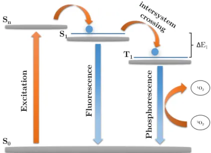
Figure 1.3: Band formation from molecular repeat unit to π-conjugated polymer. When a conjugated polymer is exposed to light, which is an electromagnetic wave, the electrons can go to an excited state if the energy (frequency) of light is enough for the excitation. The absorbed energy allows the electrons to travel from HOMO to LUMO. When the electrons are in this excited state, they are extremely unstable and tend to come back to the ground state to reduce their energy and gain stability. The relaxation of electrons from an excited state to the ground state can happen in two possible ways: fluorescence and phosphorescence. Fluorescence occurs when the electrons in the singlet-excited state directly travel back (relax) to singlet ground state. During this relaxation process, photons lose
Figure 1.4: Jablonski diagram demonstrating fluorescence and competing path-ways for molecular relaxation from an excited state. Reprinted with permission from [31]. Copyright (2015) American Chemical Society.
the heat lost to the environment), so the emitted energy (frequency) will be less than the absorbed energy. Fluorescence is the primary emission pathway for con-jugated polymers. If the excited state electrons follow a nonradiative relaxation pathway from singlet-excited state to triplet-exited state, the intersystem cross-ing will happen. The radiative relaxation from triplet-excited state to scross-inglet ground state is called phosphorescence. All these phenomena are represented as the Jablonski energy diagram in Figure 1.4.
To use conjugated polymers or oligomers in applications such as drug delivery or cell labeling, they should be water-soluble [32]. Most of these conjugated poly-mers due to lack of polar functional groups are not water-soluble, so the best way to use them in aqueous systems (biomedical applications) is to make them water dispensable and make a stable colloidal solution out of them. The most typical way to make them water-dispersed is fabricating their nanoparticles. Fabrication of water-dispersed conjugating polymer nanoparticles can be done in two com-mon ways: nanoprecipitation technique and miniemulsion. In the miniemulsion method, the conjugated polymer, which is dissolved in a water-immiscible sol-vent, is added to an aqueous surfactant solution under ultrasonication. In this case, the size of nanoparticles will be in the range of 30-500 nm depending on the power of ultrasonication and its duration. In the nanoprecipitation technique,
the hydrophobic polymer is dissolved in a good organic solvent such as THF or DMSO and then gradually added (dropwise) to a poor solvent such as water, under ultrasonication. As the hydrophobic polymer or oligomer enters the water, to prevent itself from interacting with water or at least minimize this interaction tries to form spherical nanoparticles. The size of nanoparticles, in this case, de-pends on the concentration of polymer in the good solvent, amount of the water, temperature, and pH of solutions, power and duration of ultrasonication, and rate of evaporation of the organic solvent from the final solution. With this method, nanoparticles smaller than 100 nm can be formed. The advantage of this method is that it does not require any other additives such as surfactants [33].
1.2.2
Application
The bandgap of conjugated polymers can be modified to obtain the desired op-tical properties. These opop-tical and other exceptional properties allowed the con-jugated polymers to be used in vast kinds of applications. The applications of conjugated polymer nanoparticles have been demonstrated in energy [34], cata-lysts for photocatalytic hydrogen evolution [35], electroluminescent devices [36], optoelectronics [37], and biomedical [38].
1.3
Plasmonic Nanoparticles
Nanoparticles, whose electron density can couple with the electromagnetic waves having wavelengths larger than the particles, can be called plasmonic nanoparti-cles [39]. Depending on the size and geometry of plasmonic nanopartinanoparti-cles, they can show remarkable absorption, scattering, and coupling properties, which will enable them to be exploited in many applications.
1.3.1
Properties and Applications
Some of the metal nanoparticles display resonance in the visible region, which can enable them to absorb a portion of the visible light spectrum. Their solu-tions exhibit vivid colors due to a phenomenon called localized surface plasmon resonance (LSPR). Gold (Au) [40] and silver (Ag) [41] nanoparticles have a quite strong resonance in visible range. Copper (Cu) nanoparticles [42] also show a great resonance, but because of surface oxidation, they are not stable. Resonance of palladium (Pd) and platinum (Pt) nanoparticles are weak in visible region [43]. Resonance of aluminum (Al) nanoparticles occurs in the UV region [44], which is used in a variety of applications. As mentioned earlier, the shape and size of plasmonic nanoparticles are affecting their optical properties. Optical proper-ties of the nanomaterials are also tightly bonded to their electronic configuration and physical structure. For instance, quantum confinement in semiconductor nanoparticles like CdSe causes a shift in its emission spectra [45]. As the size of semiconductor particle decreases below its Bohr radius, the electrons will be more confined in the material. This confinement will increase the bandgap of the material. The Bohr radius of CdSe is 5.6 nm [46], which means if the particle size goes smaller than 5.6 nm, the emission shifts to lower wavelengths. The optical properties of plasmonic nanoparticles can be explained with the help of Surface Plasmon Resonance (SPR). When a plasmonic metal nanoparticle is irra-diated by light, the oscillating electric field causes the free electrons (electrons in conduction band) to oscillate coherently. This oscillation frequency depends on the density of electrons, the effective electron mass, dielectric constants of both
the medium the metal, and the shape and the size of the charge distribution at the surface, which corresponds to the shape and size of the nanoparticle. The resonance can occur more effectively for shorter wavelengths in smaller and more spherical particles. Thus, a solution of 20 nm spherical gold nanoparticles is red. For gold and silver nanoparticles, this frequency is in the visible region. This will allow estimating the shape and the size of the nanoparticles with UV-Vis spec-troscopy. As the size of nanoparticles increases, the absorption occurs in lower energies (red region) and the solution color will be bluer. If the shape of the gold nanoparticles changes from spherical to non-spherical, e.g., urchin shape, the color of the solution changes to blue since the urchin shape particles are a better scatterer rather than an absorber [47], [48]. Changing the environment of nanoparticles will change the plasmonic resonance frequency; therefore, capping nanoparticles with organic and/or inorganic materials (core-shell nanostructure) can cause a significant shift in surface plasmon absorption maximum [49]. Studies also showed that increasing the dielectric constant of the surrounding medium will make the SPR peak broader [50]. The wide-ranging tunable optical properties of plasmonic nanoparticles enabled them to be tuned for specific applications. The application of the plasmonic nanoparticles has proved in biomedical [51], energy conversion [52], and surface-enhanced Raman spectroscopy (SERS) [53].
1.3.2
Gold Nanoparticles
One of the most studied plasmonic nanomaterials is the gold nanoparticle. Exten-sive potential applications of gold nanoparticles (AuNPs) in bio labeling, cataly-sis, drug delivery, and therapies due to their novel optical and electrical properties have attracted many scholars’ attention in recent years [54]. AuNPs because of their straightforward synthesis, functionalization and characterization, biocom-patibility, and unique optical properties have been widely used in a variety of applications. AuNPs tend to penetrate to the tumor cells, and this will enable them to scatter the irradiated light, which will expose the location of the tu-mor [55]. The size and the shape of AuNPs influence their optical properties, so it is necessary to control these parameters during the synthesis.
1.3.2.1 Synthesis
The synthesis of gold nanoparticles can be done in both top-down or bottom-up approaches. Top-down approaches are possible, but they are much more challeng-ing in comparison to bottom-up approaches. Laser ablation synthesis is one of the most common top-down approaches for the synthesis of gold nanoparticles [56]. In bottom-up approaches, however, the nanoparticles are synthesized from atomic building blocks; therefore, the control of the morphology, arrangement, and size of these nanoparticles is much easier. A variety of methods, including chemical, thermal, electrochemical, and sonochemical, have been introduced for the synthe-sis of AuNPs. The preparation of the AuNPs by chemical reduction method has two steps. First, the reduction of gold ions by the agents and second, adding the stabilizer agents to avoid the aggregation. One of the most famous methods for synthesis of the gold nanoparticle is adding chloroauric acid to the trisodium cit-rate aqueous solution, which is introduced by Turkevich in 1951. In this method, the gold ions will be reduced by the trisodium citrate (adding trisodium citrate to boiling gold solution). This method can produce gold nanospheres up to 20 nm. Citrate ions, which were reducing agents, can also act as a stabilizer. [57]. Frens improved the method of Turkevich in 1973. In this optimized method, gold nanoparticles have been produced in the range of 15-150 nm by controlling the ratio of precursors. For instance, using a high concentration of trisodium citrate will stabilize the solution faster; therefore, smaller gold nanoparticles can be achieved. However, using a low concentration of trisodium citrate will end up to bigger particles because the particles have more time to aggregate [57]. Some studies have reported that smaller particles and narrower size distribution can be obtained if the inverse sequence of adding precursors being followed (adding chloroauric acid to boiling trisodium citrate). This method is called reversed Turkevich [58]. Shulz et al. have reported by controlling the pH and adding EDTA more spherical nanoparticles can be produced.
1.3.2.1.1 Seed-mediated Growth Method The seeding growth method is relatively quick, easy, and cheap. In this method, first, small gold nanoparticles
are prepared then these small nanoparticles serve as the center of condensation for further growth of gold nanoparticles [59].
1.3.2.1.2 Non-aqueous Gold Colloidal Sols Aqueous sols in some cases are not desirable, therefore using organic solvents for the synthesis of gold nanoparticles is preferred. Sols obtained in organic solvents are usually unstable (they tend to aggregation and eventually from sediment) and they are highly polydisperse. For preventing aggregation, stabilizing agents such as PVP can be used to prepare gold nanoparticles. Brust-Schiffrin method is a conventional method to prepare gold nanoparticles in a two-phase system [54].
1.3.2.1.3 Ultrasound-assisted Synthesis of Gold Nanoparticles One of the methods, which is very useful in synthesizing the gold nanoparticles is the ultrasound-assisted synthesis of gold nanoparticles. In most of the synthesizing methods, for mixing the precursors and acceleration of reaction, the stirrer will be used; however, in the ultrasound-assisted method, the reaction will be done under ultrasonication. The particles produced by the ultrasound-assisted method are usually smaller, and highly monodisperse [60], [61], [62]. These benefits cannot be achieved by a conventional magnetic stirrer.
1.3.2.1.4 Conjugated Polymer-assisted Synthesis of Gold Nanoparti-cles By utilizing the redox chemistry of conjugated polymers for reducing the gold ions, gold nanoparticles can be directly synthesized through a conjugated polymer mediated technique. This method provides modulation of the morphol-ogy, structure, and the size of the gold nanoparticles and nanocomposite and enable the one-step synthesis of gold nanoparticles [63]. Only metal ions hav-ing a higher reduction potential than conjugated polymer can be spontaneously reduced to form zero-valent metal; otherwise, the additional electric field is nec-essary to force the reduction of these metal ions [64]. The reduction potential of Au3+/Au is 1.52 V, which means its ions can be spontaneously reduced to
1.52 V.
1.4
Core-Shell Nanostructures
The idea of designing new structures, which can provide a combination of prop-erties of different materials in one platform has become more realistic with recent developments in nanotechnology. A core-shell structure is a well-organized nanos-tructure consisting of two, three, or more types of distinct nanocomponents con-structed based on cores (inner material) and shells (outer layer material). Many different properties can be obtained by wisely harmonizing the core(s) and the shell(s) of such materials.
1.4.1
Synthesis of Core-Shell Nanoparticles
The synthesis of core-shell nanoparticles (CSNs) can be done in both top-down or bottom-up approaches. Top-down approaches are possible, but they are much more complex in comparison to bottom-up approaches. Microfabrication tech-niques and mechanical stress are the most common top-down approaches for the synthesis of CSNs. In bottom-up approaches, however, the nanoparticles are synthesized from atomic building blocks; therefore, controlling the morphology, arrangement, and size of these nanoparticles is much simpler. The bottom-up synthesis of CSNs can be done in a stepwise or one-pot manner. Preventing lengthy separation and purification processes, and the simplicity of the whole reaction procedure are the main benefits of the one-pot synthesis over the step-wise synthesis. With this in mind, the one-pot synthesis of the CSNs would be much more profitable for scholars. The polymerization chemical reaction is one of the most common methods for synthesizing the CSNs. In this method, surface-active materials such as CuO and SiO2 nanoparticles will be selected as the core.
The polymerization will be initiated at the surface of these nanoparticles (cores), and ultimately, the polymeric shell will be formed over the core [65]. With this
method, a shell with a thickness of 2-10 nm can be obtained. The surface chem-ical reaction (surface deposition) is another method, which can be used for the synthesis of the CSNs. In this method, both the core and the shell are dispersed in an aqueous solution. Changing the pH of the solution and/or heating it can cause the formation of CSNs. TiO2 @ SiO2 is one of the CSNs that can be
syn-thesized with this method [66]. The ultrasonic chemical method also can be used for the synthesis of the CSNs. In this method, the ultrasonic cavitation effect causes an increase in the chemical interaction between the surface of the core and the coating metrical and the CSNs can be formed more efficiently. Depositing gold on the SiO2 nanoparticles is one of the examples of this method.
1.4.2
Properties
CSNs can possess completely new properties and/or synergistic properties among the cores and shells. Such features are one of the reasons that CSNs have received increased attention in recent years. Theoretically, CSNs can be designed almost in infinite ways. CSNs can be divided into four classes depending on the compo-sition and the arrangement of the core and shell materials. Inorganic/inorganic, inorganic/organic, organic/inorganic, and organic/organic are typical types of CSNs [67], [68], [69]. Nanoparticles with metal (inorganic) cores and polymer (organic) shells are captivating materials. Both the properties of the core and the shell can be exploited in this kind of CSNs. These CSNs show a complex be-havior while they are dispersed in a liquid. These complex bebe-haviors are because of the interactions of core and shell, shell and shell (repulsion), and shell and continuous phase (dispersant). As a result of these behaviors, they can be called smart multi-functional materials. In these hybrid structures, the shell has piv-otal functions. Prevent aggregation and protecting the core are the most crucial functions of the shell. Although it is mentioned that CSNs can be designed al-most in infinite ways, practically, there are obstructions. Therefore, selecting the materials for the core and especially the shell(s) is not a straightforward task and requires further studies. For instance, the conjugated polymer-assisted synthesis of metal nanoparticles is only possible when the reduction potential difference
of the metal and the conjugated polymer is greater than zero. Structural and compositional parameters of CSNs can affect CSNs properties. Some of these parameters can be seen in Figure 1.5.
Figure 1.5: Effective parameters on the properties of CSNs.
1.4.3
Applications
CSNs can possess both the properties of the core and the shell in a synergistic manner; therefore, it is expected that they can be utilized in many applications. Drug delivery [70], hyperthermia [71], catalysis , sensing [72], energy storage [73], solar energy conversion [74], electromagnetic wave absorption [75], environmen-tal [76], and combined photothermal and photodynamic therapy [77] are the some these applications.
Figure 1.6: Applications of CSNs.
1.5
Colloidal Systems
A colloidal system implies a dispersed phase that has been disseminated all over a dispersing medium, which consists of two or more components mixed. Colloids can be a two-phase system or a single-phase (true solution) depending on the interaction of the dispersed phase particles and the continuous dispersant phase. The colloidal particles have a high interfacial area. It is also known that smaller particles possess a higher interfacial area. This causes the colloidal systems to have unique properties; therefore, for a better understanding of these properties, it is necessary to study colloids and surface chemistry together. According to the interaction of the dispersed phase particles and the continuous dispersant phase, colloids can be categorized as lyophobic or lyophilic. “Lyo” refers to the contin-uous dispersant phase, “phobic” means fearing, and “philic” loving. Lyophobic colloids maintain very high interfacial free energy; therefore, they are thermo-dynamically unstable and have a high tendency to aggregate so that they can reduce this interfacial free energy by forming a two-phase system. Lyophilic col-loids, however, because of owning relatively stronger forces of interaction among dispersed phase particles and dispersion medium, are single-phase and their sta-bility is much higher [78]. Some properties of colloids depend on the type of them. For instance, surface tension in a lyophilic colloid is less than its medium;
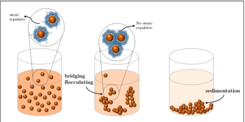
however, in lyophobic colloid is nearly the same as its medium. In lyophilic col-loids, viscosity is usually higher than the medium. However, viscosity is almost the same as the medium in lyophobic colloids. When a colloid is called stable, it means that the repulsive forces among its particles are dominant. These repulsive forces can be steric or electrostatic. In steric repulsion, two particles preventing entwining due to the presence of active components on their surface. Electro-static repulsion, however, is due to the presence of charges on the surface of the particles that prevent them from being close enough and start aggregating [79]. One of the best ways to roughly evaluate the stability of the colloidal solution is zeta potential calculation (measurement) [80]. The magnitude of repulsive forces is directly proportional to zeta potential absolute value. Negative values of zeta potential correspond to negatively charged particles, and positive values of zeta potential correspond to positively charged particles. Electrostatic repulsions are more effective than the steric repulsions. Usually, the absolute value of zeta po-tential of colloids, which their particles undergo electrostatic repulsions is higher than the particles undergo steric repulsions. Although it is mentioned in the lit-erature that solutions owning zeta potential absolute value of 30 mV and higher are stable, some colloidal systems are stable even with zeta potential absolute values of less than 30 mV [81], [82], [83]. Hence, more studies are needed for the investigation of the stability of colloids. Adding an electrolyte to the lyophobic colloidal solutions can make them unstable. The phenomenon, which is called flocculation caused by forming aggregates and eventually sediment by the grav-ity [79]. All of the colloids cannot be fitted into one of these classifications, and some of them may have common characteristics with more than one of these cat-egories; therefore, it can be said that whatever behavior like colloids can be called a colloid.
Figure 1.7: Electrostatic stabilization of colloids; adding strong electrolytes will cause the particles to lose their charges and this end up with aggregation and eventually sedimentation.
Figure 1.8: Steric stabilization of colloids; any modification usually ends up with aggregation and eventually sedimentation.
1.6
Photothermal Therapy
Using the heat for tumor therapy has been recorded in history. In 1700 BC, the glowing tip of a fire drill has been used for breast cancer therapy. With further developments in technology, the source of heating has been changed. Mi-crowaves [84], ultrasound waves [85], [86], and radiofrequency [87], [88] are the modern sources for the heating. Heating a specific target tissue to a temperature in a range of 41-47◦C with a duration of ten minutes, can be defined as Hyper-thermia [89]. Tumor cells, because of their poor blood support, cannot tolerate the heat as much as a normal tissue can do. With this in mind, heating the tumor in the mentioned range of temperature can damage the tumor. The drawback of hyperthermia with the conventional heat source is the permanent damage to the membrane of healthy cells as well as the tumor cells. By utilizing lasers as a heat source, scientists could tackle this problem partially with thermal damaging the tumor tissue in a controlled and confined way. Although the amount of damage is reduced substantially, still the biggest shortcoming of laser therapy is its se-lectivity. Both the normal and tumor cells will be affected in the path of laser beam [90]. Photothermal therapy (PTT), is another method for tumor therapy. In this method, the photothermal agents are utilized to achieve the heating of the local environment selectively [91], [92], [93], [94]. Gold nanoparticles, thanks to their strong absorption in the visible and NIR regions because of their sur-face plasmon resonance (SPR) oscillations, are widely being used in PTT. Since the gold nanoparticles are plasmonic, the treatment with gold nanoparticles is called plasmonic photothermal therapy (PPTT) or (PPT). Light-to-heat conver-sion efficiency and absorption cross-sections are two of the main properties of the PPTT agent, which should be considered for the initial design. Plasmonic metal nanoparticles such as gold and silver have a higher resistance to photobleaching, and their absorption cross-sections due to their SPR is around 5 to 6 times greater than non-plasmonic metal nanoparticles. With this in mind, the best candidates for PTT agent can be selected form these novel metals [95]. If cancer cells or bacteria (in the presence of gold nanoparticles) have been irradiated with a laser beam with a specific wavelength (usually at which SPR absorption occurs), the laser energy will be absorbed by gold nanoparticles in a few femtoseconds and
part of absorbed energy will be converted to heat, which can kill the cancer cells or bacteria. To discuss this in more detail, when a gold nanoparticle is exposed to the light, its electrons can be excited from the ground state to excited state by absorbing the light energy. These excited electrons will relax back to the ground state through nonradiative decay channels. This relaxation will increase the overall kinetic energy and ultimately overheat the local environment of the nanoparticle. Conversion of light energy to heat can be initiated with the collision of electron-electron and then followed by electron-phonon interactions will create a hotspot, which can increase the temperature by tens of degrees and eventually cause permanent damage to the wall or the DNA of the cell or the bacteria (Fig-ure 1.9). The shape, size, and surface charge of the gold nanoparticles are crucial for PPTT. These properties are directly affecting the yield of the conversion of light energy to heat. Positively charged gold nanoparticles can effectively bind to the surface of the gram-negative bacteria, which are negatively charged.
Figure 1.9: Scheme of PTT-Killing of E. coli bacteria; the generated heat will cause permanent damage to the bacteria wall.
Figure 1.10: Dissipation of energy through plasmon-mediated transformation mechanisms caused by SPR.
1.7
Photodynamic Therapy
Photodynamic therapy (PDT), also known as photochemotherapy is a tumor therapy method. In this method, a chemical that is photosensitizer will be in-jected into the body and after a certain amount of time absorbs by the tumor cells [96], [97], [98]. A photosensitizer (PS) is a molecule that can be activated by light in order to generate reactive oxygen species (ROS), such as singlet oxygen (1O
2). When a PS is stimulated with light, it will react with triplet oxygen (3O2)
and generate the singlet oxygen (1O
2) that is toxic to cells and tissues. The1O2
induces disarrangements in the cell wall and the DNA that will cause irreversible damages. An ideal PS should be a pure compound with a determined chemical structure and contain no heavy metals. It should maintain a high conversion yield of triplet oxygen (3O2) to singlet oxygen (1O2), low accumulation rate in the skin,
and be inactive (harmless to the cells and the bacteria) in the dark. Porphyrin-based PSs are commonly used in clinical applications since their high capacity of singlet oxygen generation and biocompatibility. PSs can be also be used in water treatment [99]. Conjugated-polymer-based PSs are much more efficient in singlet oxygen generation in comparison to their small-molecule analogs. This can be caused by better intersystem crossing (ISC) which will end up with more singlet oxygen production [100], [101], [102], [103]. ISC is an isoenergetic radiationless transition between two electronic states having different multiplicities [104]. Con-jugated polymers due to special electronic configuration own many energy levels in each energy band [105]. This special electronic configuration will enable the conjugated polymers to have less energy difference between S1 and T1 (∆E),
which is profitable for the singlet oxygen generation [106].
Cancer cells, in comparison with healthy cells, are more sensitive to hyper-thermia therapy due to their high growth rate and fast metabolism. For having efficient PDT, the light should penetrate through tissue. The magnitude of wave-length and depth of penetration are directly proportional; therefore, scientists are looking for such PS having an appropriate light absorption at near-infrared region (NIR). Besides the penetration depth, it is better to choose less energetic lights to minimize the side effects associated with PDT. Hemoglobin in the blood
Figure 1.11: Jablonski diagram of small molecule PS for generation of 1O 2.
Figure 1.12: Jablonski diagram of conjugated polymer PS for generation of 1O2;
in comparison to small molecule PS, the 1O2 generation efficiency of conjugated
absorbs light up to the wavelengths of 600 nm. It means that the tissue should be illuminated by the wavelengths higher than 600 nm. At the wavelengths higher than 850-900 nm, the energy for the conversion of triplet oxygen to singlet oxygen cannot be granted; therefore, usually, the red light will be used in PDT [103].
Figure 1.13: A simplified scheme of the mechanism of PDT-induced tumor de-struction.; singlet oxygen generated with PS will cause substantial damage to the tumor cell wall.
The side effect of photodynamic therapy is negligible, and it does not create any scar. The biggest drawback of PDT is that the PS remains in the body and causes problems while the patient is exposed to the light.
1.7.1
Metal-Enhanced Singlet Oxygen Generation (ME
1O
2)
Multidrug resistance (MDR) in Escherichia coli (E. coli) has become a serious issue that is not only increasingly observed in humans but also is widespread in veterinary medicine worldwide. Therefore, new and effective alternatives to conventional antibiotics should be developed urgently. The resistance of E. coli to most or all of the antibiotics has been observed [107]. An emerging alter-native approach for fighting pathogens such as PDT is an outgrowth of MDR. Since PDT does not possess any specific mechanism of action, regardless of the kind of bacterium and its level of resistance, it can be effective for most of the cases [108]. In some cases, however, the PDT agent is ineffective, and it needs further reinforcement. As mentioned earlier, the gold nanoparticles because of their high resistance to oxidation, possessing a well-known absorption peak, rela-tively easy synthesis, and almost no toxicity in the dark can be used for ME1O2.
Considering this, improving the singlet oxygen generation efficiency will enhance the overall effectiveness of therapy. It can act as a reinforcement and compensate for the low killing efficiency provided by PS alone. Hybrid core-shell structures can be suitable for the ME1O
2 and can provide higher singlet oxygen generation
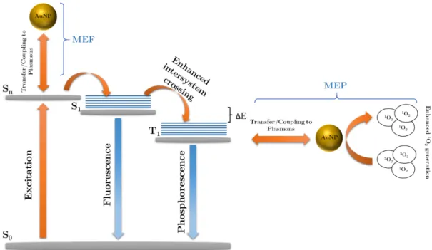
capacity for killing the bacteria [109]. In the presence of metallic nanoparticles such as gold and silver next to or inside the fluorophore, near-field interactions of fluorophores with metallic nanoparticles will occur. These interactions due to mirror dipole effect will enable both metal-enhanced fluorescence (MEF) [110] and metal-enhanced phosphorescence (MEP) [111], [112]. The higher singlet oxy-gen oxy-generation can be an outcome of an increase in the net system absorbance, enhancement in the triplet excited state yield of the sensitizer, and enhancement in the intersystem crossing. Figure 1.14 summarizes the previous statements and showing the Jablonski diagram of the photosensitizer and metal-enhanced singlet oxygen generation.
Figure 1.14: Modified Jablonski diagram of the photosensitizer and metal-enhanced singlet oxygen generation. Adapted with permission from [113].
Figure 1.15: The expected performance of Au@COL and COL nanoparticles in the singlet oxygen generation. Au@COL nanoparticles, theoretically due to ME1O
2 possess higher singlet oxygen generation capacity. Adapted with
1.8
E. coli bacteria
The oldest form of cellular life is bacteria. They can be classified into four classes according to their composition of the prokaryotic cell wall; gram-positive bacte-ria, gram-negative bactebacte-ria, bacteria with chemically different cell walls, and the bacteria with no cell wall. Gram-positive bacteria are such bacteria that take up the crystal violet stain, and their gram stain test is positive. Oppositely, gram-negative bacteria are such bacteria that retain the crystal violet color, and their gram stain test is negative. Bacillus subtilis and Escherichia coli are gram-positive and gram-negative bacteria, respectively. The gram-positive bacteria possess a single-layered cell wall, which is rigid due to the high amount of peptidoglycan. The gram-negative bacteria, however, own a bi-layered cell wall with less rigidity in comparison to gram-positive bacteria. The wall in gram-positive bacteria is porous and usually thicker than gram-negative bacteria. Gram-negative bacteria possess an outer membrane in their cell wall, which results in a low degree of permeability. This outer membrane is the main reason why the gram-negative bacteria resist many antibiotics. The same reason can also explain the higher prevalence of gram-negative infections. E. coli is a gram-negative bacterium with bacillus (rod-shaped) shape. It retains wavy and uneven walls and can be found in the gut of warm-blooded animals and humans. Most strains of E. coli are not harmful to the human body [114]. However, some strains, such as shigatoxigenic E. coli (STEC) and verotoxigenic E. coli (VTEC), can cause severe diseases. E. coli can easily be transmitted to humans, mainly by the consumption of contam-inated foods (usually raw foods). During the last decades, a rising number of resistance genes have been discovered in E. coli isolates. These resistance genes are mostly acquired by horizontal gene transfer [115]. E. coli can act as a donor and recipient of resistance genes. High capacity to accumulate resistance genes, made the E. coli to be considered as a real public health concern. Multidrug resistance (MDR) in Escherichia coli (E. coli) has become a critical problem af-fecting both the animals and humans. As described earlier, E. coli, like other gram-negative bacteria, holds an outer membrane, which allows it to resist the ordinary antibacterial agents. PDT can be a solution, but it is reported that E.
PS is needed for the PDT-killing of gram-negative bacteria. To execute antimi-crobial PDT, the PS has to breach into the cell walls of the bacteria. Considering this, the membrane barriers in the gram-negative bacteria, limit the PS pene-tration, especially if the PS is anionic (negatively charged). Hence, PDT-killing of gram-negative bacteria is much harder than the gram-positive bacteria [117]. The gram-negative bacteria enjoy negatively-charged cell wall because of teichoic acid residues [116]. Therefore, cationic PS (positively charged) can be used to bind with the cell wall of gram-negative bacteria.
1.9
Previous Works with Red-Emitting
Conju-gated Oligomer
Balkan et al. have reported the one-pot synthesis of hybrid silver-conjugated oligomer nanoparticles. This work has proven that the spontaneous reduction of silver ions by COL is possible, and by modifying the reaction conditions, nanopar-ticles in different structures such as core-shell and raspberry and different sizes can be produced. For instance, different concentration ratios such as 1:1, 1:2, 1:4 (Ag:COL) have resulted in different optical and morphological properties. The resulting nanoparticles further characterized by UV-Vis and fluorescence spec-troscopy, SEM, TEM, and DLS. These analyses showed that with increasing the concentration of silver ions, the fluorescence intensity quenches. The hydrody-namic diameter measured by DLS for the hybrid core-shell nanoparticles with the configuration of the silver core with conjugated oligomer shell (Ag@COL) was 50 nm. Possible applications for such hybrid core-shell nanoparticles are claimed to be in photocatalysis, plasmonic sensing, and theranostics [118]. Successfully spontaneous reduction of silver ions indicates the reduction potential of COL is at least 0.8 V. It means that it can theoretically reduce the metal ions possessing the reduction potential of 0.8 V and higher. With this in mind, the spontaneous reduction of gold ions would be possible with this oligomer since the reduction potential of Au3+/Au is 1.52 V. Considering this, the one-pot synthesis of hybrid
Chapter 2
Introduction to measurement
techniques
2.1
Dynamic Light Scattering and Zeta
Poten-tial
Dynamic light scattering (DLS), also known as photon correlation spectroscopy and sometimes as quasi-elastic light scattering is a non-invasive technique for measuring the size of particles and molecules in suspensions.
DLS measures the speed at which these particles undergo this Brownian mo-tion. Brownian motion is a random movement of particles and molecules. The origin of this random movement is that particles are constantly being bombarded by the solvent molecules that surround them. Small particles diffuse rapidly while large particles diffuse slowly. The velocity of this Brownian motion is called the translational diffusion coefficient (D). The size of particles can be calculated by the Stokes-Einstein equation:
d(H) = kT
3πµD (2.1)
where,
d(H) = hydrodynamic diameter D = translational diffusion coefficient k = Boltzmann’s constant
T = absolute temperature µ = viscosity
Hydrodynamic size is the diameter of a hard-sphere that diffuses at the same speed as the particle and molecule being measured. It depends on various pa-rameters, such as ionic strength, surface structure, and shape of particles. Ionic strength will be effective on Debye length. Debye length is the thickness of the electrical double layer formed by the cloud of ions that exists around the surface of the particle and the molecule. Debye length is inversely proportional to ionic strength, so as the ionic strength goes higher, it compresses the Debye length; therefore, the recorded size from DLS for any particle suspended in a salt solution will be smaller than the same particle in deionized water. The surface structure can influence hydrodynamic diameter because it affects the diffusion speed. If the shape of particles is irregular, they undergo a random diffusion. During a measurement, the instrument will measure different diffusion coefficients depend-ing on the orientation of the particles; therefore, the reported average size might not be reliable. Small changes in the length of rod-shaped particles will change the rod’s diameter; however, because it hardly affects the diffusion speed, DLS cannot detect the size change. The sample holder can be a disposable plastic
(polystyrene), glass, or quartz cuvette. The disposable holder cannot be used for most organic solvents such as THF. For organic solvents, usually, the glass cuvette is being used. In the reported results, the intercept in the correlation function diagram is the signal to noise ratio. The values higher than 0.9 deter-mine a high-quality signal. The amount of time it takes the correlation function to begin the decay indicates the mean size of particles. Faster decays, usually mean smaller particles. The slope of the correlation function shows the polydis-persity of the sample. The higher slope (more vertical) means less polydispolydis-persity in the sample. The baseline exposes whether there are aggregations (big parti-cles) or not. The flat and smooth baseline shows there are no big particles. For analyzing the correlation function, two different analyses are performed: First, the cumulants analysis and second, the distribution analysis. Cumulants analysis provides mean size (z-average), and polydispersity index (PDI) and distribution analysis provides the distribution of sizes. For cumulants analysis, only the dis-persant refractive index and viscosity are required. If the z-average is much higher than the reported size distributions in the results, big particles are present in the sample. The z-average diameter and PDI are tightly bonded in the way that reported z-average diameter of particles with PDI of 0.08 or less are more likely to be the same as average sizes reported by TEM images. However, in the PDI of 0.2 or higher, the z-average diameter is greater than the reported size in dis-tribution analysis. Number, volume, and intensity disdis-tributions can be found in the software report. Each of them can be useful for specific purposes. As it is mentioned, the larger particles scatter the light more than the smaller particles so, in intensity distribution, the reported sizes are based on the particles, which scattered the light more efficiently. So the reported sizes in intensity distribu-tion are larger than average sizes reported by TEM. The intensity distribudistribu-tion diagram is the best source to investigate the presence of large particles inside the sample. In volume distribution, the reported size is smaller than the inten-sity distribution reported size, and it is based on the volume of the particles. In number distribution, the number of particles having the same size determines the reported size. The reported size by number distribution is smaller than the sizes reported by intensity distribution and volume distribution, and it is much closer to reported size by TEM. Although reporting the number distribution is
usually preferred, but it is more accurate to report the sizes by all three distri-bution in the articles. Zeta potential is the overall charge a particle acquired in a particular medium. Zeta potential depends on both the chemistry of the surface of particles and the dispersant. Zeta potential can be calculated with the help of electrophoretic mobility. The sample is inserted into a capillary cell with electrodes. As the instrument applies the voltage across two electrodes since the distance of two electrodes is known, the electric field strength can be calculated by instrument. The charged particles can gain velocity, and the instrument can measure the velocity of these particles by Doppler shifts. Small changes in pH and concentration of ions can lead to dramatic changes in the zeta potential value. For electrostatically stabilized dispersions, the higher the value of zeta potential, the more stable the dispersion is likely to be. The effect of the pH on the value of the zeta potential can determine the isoelectric point location and how much acidic or basic the surface of particles are. If a charged particle has been dropped into the water, oppositely charged ions (counterion) will associate right around that particle and create a layer called the stern layer. Right after the stern layer and up to a particular distance mixture of counterions and coions form another layer named the diffuse layer. These two layers together are called the electrical double layer. Zeta potential indicates a potential that belongs to an arbitrary plane named slipping plane, which is located close to the stern layer (Figure 2.2). Electrical double layer width is reversely proportional to ionic strength. The va-lency of the ions will also effect double layer thickness. For instance, Al3+ will
shrink the electrical double layer more effectively in comparison with Na+. Zeta potential does not indicate the actual charge of the surface of particles, so it determines how much effective is the surface charge. The zeta potential can be calculated by Hemry’s function. In this function, depending on the polarity of the medium Huckel (non-polar) and Smoluchowski (polar) approximation can be used. The stability of colloidal systems is determined by the balance of repulsive and attractive forces. If there is mutual repulsion, then the dispersion will resist flocculation. Oppositely, if there is not repulsion, then flocculation or coagulation will eventually take place.
Figure 2.2: The Illustration of zeta potential. Reprinted with permission from [119].
2.2
Ultraviolet-visible Spectroscopy
In ultraviolet-visible spectroscopy (UV–Vis or UV/Vis) the electromagnetic wave with the wavelength in the range of 200 nm to 800 nm will be emitted to the cuvette (usually a pathlength of 1 cm) containing the sample. The interaction of the light and the chemicals in the sample will result in absorption in the spectrum. The wavelength and the magnitude of the absorption (location and intensity of peak) can reveal information about the chemicals or changes in the structure. In the UV-Vis spectrum, the Y-axis is optical density (OD), which is dimensionless, and the X-axis is the wavelength in nanometer. The instrument can calculate the optical density, by the Lambert-Beer law, which is more commonly known as Beer’s law.
OD = εcl (2.2)
where,
ε is molar attenuation coefficient of the material in L.mol−1.cm−1 c is the molar concentration of those species in L.mol−1 and
As it is demonstrated in Equation 2.2, the OD value is directly proportional to the concentration of the sample. This direct relation is only valid when there is no aggregation in the sample. UV–Vis can be used for comparing two different compounds. During the comparison, usually, the shifts in position and intensity of peaks are considered. In the bathochromic shift, the absorption peak moves towards the longer wavelength or lower energies. This can be due to the formation of different auxochromes (a group of atoms attached to a chromophore), adding conjugation and solvent effect. When a solute is dissolved in a polar solvent if the excited state of solute is more polar in comparison to its ground state, the polar solvent tries to stabilize the excited state more than the ground state. In this case, the gap between the excited state and the ground state (bandgap) decreases, which means less energy is required for the excitation, and there will be a redshift in the absorption spectrum. The hypsochromic shift, also known as the blueshift is the absorption peak move towards the shorter wavelengths or, the higher energies. It may be caused by the removal of conjugation or by the change in the polarity of the solvent. On the contrary of redshift, when a solute is dissolved in a polar solvent if the excited state of solute is less polar in comparison to its ground state, the polar solvent tries to stabilize the ground state more that excited state. In this case, the gap between excited and the ground states (bandgap) increases, which means higher energy is required for the excitation, and there will be a blueshift in the absorption spectrum. In addition to these two shifts, there are other possibilities related to the change in the intensity of peaks. The hyperchromic effect is an effect due to which the intensity of absorption maximum increases. This can be caused by changes in the absorption coefficient (chemical structure) or concentration. An excellent example of this effect is the conversion of the pyridine to 2-methylpyridine in the same concentration, which causes a redshift from 257 nm to 262 nm and an increase in the absorption coefficient from 2,750 to 3,560 L.mol−1.cm−1. Another effect is hypochromic. Hypochromic is an effect due to which the intensity of an absorption maximum peak decreases. The best example of this effect is the conversion of the biphenyl to 2-methyl biphenyl in the same concentration which causes a blueshift from 250 nm to 237 nm and a decrease in the absorption coefficient from 19,000 to 10,500 L.mol−1.cm−1. In the case of gold nanoparticles, UV-Vis spectroscopy can


![Figure 2.2: The Illustration of zeta potential. Reprinted with permission from [119].](https://thumb-eu.123doks.com/thumbv2/9libnet/5925218.123087/48.918.274.694.170.465/figure-illustration-zeta-potential-reprinted-permission.webp)
![Figure 2.4: Schematic diagram of the main components of TEM. Reprinted with permission from [123].](https://thumb-eu.123doks.com/thumbv2/9libnet/5925218.123087/59.918.298.661.435.1001/figure-schematic-diagram-main-components-tem-reprinted-permission.webp)
![Figure 2.5: Schematic diagram of the main components of SEM. Reprinted with permission from [123].](https://thumb-eu.123doks.com/thumbv2/9libnet/5925218.123087/61.918.265.692.353.853/figure-schematic-diagram-main-components-sem-reprinted-permission.webp)