International Journal of
Intelligent Systems and
Applications in Engineering
Advanced Technology and ScienceISSN:2147-67992147-6799 www.atscience.org/IJISAE Original Research Paper
The Effects of Speed and Flow Rate on Power in Thermoelectric
Generators
Abdullah Cem AGACAYAK
1, Hakan TERZIOGLU*
1,
Hasan CIMEN
2, Suleyman NESELI
3, Gokhan YALCIN
3Accepted : 12/02/2018 Published: 30/03/2018 x
Abstract: Geothermal energy is a kind of clean energy which has existed since the world existed. Every passing year new geotermal fields
are invented and their area of usage is increasing rapidly. In our day, where there is tendency of rising in the energy costs; the geothermal energy rise in importance as an alternative resource. Therefore, in this study the design of the thermoelectric generator which directly transforms the geothermal energy that is one of the renewable energy sources to electrical energy and the execution of the system is carried out. In the system, two different types of TEC1-12706 and TEC1-12710 thermoelectric moduls which are made up of thermoelectric semi-conductors that can be easily acquired in the markets are used in the energy transition. In the experimental studies that are performed, the power rating which thermalelectric generators produce in 3 different pressure and 3 different flow rate of hot and cold water are compared. Consequently, it is seen that the speed and the flow rate of the water is efficacious on the power which thermoelectric generators generate.
Keywords: Electricity Generation; Renewable Energy; Thermoelectric Generator; Thermoelectric Modul; Termal Performance.
1. Introduction
Energy needs and demands are increasing constantly in many countries around the world, especially in the developing countries like Turkey. While the development of technology and industry increases energy consumption on one side, it increases the damage to the environment on the other side. With the increase in environmental and energy problems, there has also been an increase in the studies carried out in recent years on energy production and its impacts on the environment around the world. With the developing technology, efforts are being made to obtain efficient, cheap and clean energy from alternative energy sources. When these studies and the environmental and economic effects of the global electricity generation systems are taken into consideration, renewable energy sources from alternative energy sources come to the forefront. Resources used as renewable energy resources in the world include geothermal energy, solar energy, wind energy, biomass energy, hydrogen energy, tidal energy generated by sea waves. Renewable energy sources other than geothermal energy have some disadvantages. These sources have negative environmental impacts though not as much as fossil sources. They can only be used at certain times of the year and therefore they cannot produce energy constantly. Their technologies are not fully developed, and their costs are expensive [1;2;3;5]. Therefore, scientists are looking for alternative energy sources such as geothermal energy etc. that do not have negative impacts on the environment, that can be used at any time of the year and that are cost-effective.
With the increasing interest in geothermal energy in recent years, the importance of thermoelectric (TE) semiconductors and related technologies has also increased. Thermoelectric modules (TEM)
have many advantages. They are long lasting, do not need maintenance, quiet, they do not have moving parts, they are reliable and have simple structures. Due to these advantages, interest in the TEMs is increasing day by day [16]. If DC voltages are applied to the ends of the TEMs, the electrons in the P-N semiconductors in their structures will move. As a result of this movement of the electrons, one surface of the TEMs is heated while the other surface is cooled. If we run this module reversed to create a temperature difference between the surfaces, modules operate as a thermoelectric generator (TEG) and we obtain DC voltage from their terminals. The more the temperature difference between the surfaces, the more electrical energy production increases. It is difficult to obtain a constant voltage because the temperature difference on the TEM surfaces depends on the sources used and these temperatures can vary over time. Therefore, for constant voltage, DC voltage needs to be stored and regulated [16].
The studies that have been carried out on this subject so far are: Kinsella et al. produced electricity using the heat of the liquid flowing with a single thermoelectric generator (TEG) that produces low electrical current and also developed a prototype electric generator to store this energy produced. They charged a 3.3 V lithium-iron-phosphate battery, which can be charged with TEG-generated electricity [13].
Atik et al. heated one surface of 8 thermoelectric modules with hot water and cooled the other surface with tap water. With the temperature difference of 70 °C, they obtained; they obtained 6V electric power and 2.5W power [6].
Fettah used the waste heat generated during operation of the solid oxide fuel battery in his work. In this study, by demonstrating the operability of a system that generates electricity using thermoelectric modules, he intended to set an example for future work. In practice, he compared water-cooled and air-cooled systems. When the Seebeck effect and the flow relation are examined, he stated that the heat convection coefficient of the air increases with the turbulent flow when the flow increases [10].
_______________________________________________________________________________________________________________________________________________________________________________________________________________________________________________________________________________________________________________________________
1 Electrical Prog., Selcuk University, Konya – 42002, Turkey
2 Elec./Electronic Engg., Selcuk University, Konya – 42002, Turkey
3 Mechanical Engg., Selcuk University, Konya – 42002, Turkey
Temizer et al. studied the technical properties of thermoelectric generators and determined the methods of electricity generation together with heating and cooling systems. They also recommended the use of thermoelectric cooling in the cooling system of automobiles. They proposed that thermoelectric cooling systems could be developed with cooling to be applied to areas close to the driver and passengers [19].
The study of Woo et al. conducted with 32 thermoelectric modules is concerned with energy generation and TEG characterization as thermoelectric generators (TEG). The TEG work consisted of the water heater, pump, 32 thermoelectric module, aluminum and hot and cold water circulated through the aluminum container. It was found that the temperature generated by TEG increases in the range of 20-50 K as the temperature increases. It is stated that the electric efficiency reaches 1.04% by reaching the maximum value at a temperature difference of T = 50 K [20].
Kim and Lai wanted to charge the car battery using a DC-DC converter, which provides voltage increase and voltage drop functions for thermoelectric generators with output voltages that vary widely [12].
Cho et al. proposed a maximum power point tracking method for thermoelectric generators without a digital control unit. The advantage of the proposed method is the half-VOC-level sampling analog monitoring cycle without DSP or microcontroller unit for calculation of peak power by sequential methods [18].
Octavian et al proposed a special DC-DC Ćuk converter developed to charge batteries with series-connected thermoelectric generators (TEG) [7].
Lertsatitthanakorn performed a cost analysis of the system by obtaining 2.4 W power and 3.2% efficiency at a maximum temperature difference of 150 °C from the waste heat of the stoves used in houses [15].
Eakburanawat obtained 7.99 W with TE element TEP1 -1264-1.5 module that converts heat energy to direct electric energy and created a system that charges the battery [9].
Kushch et al. formed 8 series groups from 9 thermoelectric generators series-connected to the 550hp diesel truck motor exhaust and mounted them parallel to each other. Thus, they determined that the output power of 72 HZ-14 Thermoelectric modules depends on the motor speed (hp) rather than the motor rotation speed (rpm) [14].
In another study, Maneewan et al. increased the temperature of one surface of the thermoelectric modules placed on the roof of the building with the temperature of the sun's rays and tried to reduce the temperature of the other surface by means of a fan. They simulated this system through a computer program. They did the design and cost analysis of the system and concluded that the system will amortize itself in about 4.36 years [17].
This study is based on geothermal energy from renewable energy sources and the model is simulated with a thermoelectric generator which transforms the heat directly into electricity for the application of the system. In the laboratory environment, at three different hot and cold water flows and pressures, system design with temperature difference is made with the copper material. Two different types of TEM were used in the system and the TEMs were also compared to each other besides the production of electric energy in a clean, easy and inexpensive manner. The impacts of the speed and flow of water on the power of the system were determined. With the experiment set up in the laboratory, electricity production was realized with the temperature difference. In this energy conversion, TEMs composed of TE semi-conductive were used. In the experimental system set, the heat required to create the temperature difference on the surface of the
thermoelectric modules was provided by the hot water flow heated from the outside and the cooling was provided by the air-supported cold water flow of the normal city water. Since the amount of energy produced by the temperature difference varied, the output voltage was fixed by connecting the DA-DA reducing-increasing converter to the TEG outputs in the most efficient test conditions in the system. This study showed that the electric power and the power obtained from the sources in the geothermal regions can vary according to the temperatures, flow rates, and water pressures. 1.1. Thermoelectric Modules
In TEM, P and N-type semi-conductive materials are electrically connected in series and thermally parallel between two insulating plates. Figure 1 shows the TEM's section [4].
Fig. 1. Thermoelectric module section appearance [11].
In order to provide thermal conductivity together besides electrical insulation, the upper and lower surfaces of the module were covered with ceramic material. TEMs can be operated in two ways. If DC voltage is applied to the +/- terminals, they can be used as a thermoelectric cooler (TEC) by Peltier effect. On the other hand, they can also be used as a thermoelectric generator (TEG) by the effect of Seebeck if the temperature difference between the surfaces is created by the influence of an external source. 1.1.1. Use of Thermoelectric Module as a Generator
As shown in Figure 2, when one terminal of each of two different types of conductive metals are connected to each other and temperature difference is applied to these two terminals, a proportional voltage difference arises in the system, which is called the Seebeck effect.
Fig. 2. Simple thermal double circuit
As seen in Figure 3, if the high temperature is applied to one of the two ceramic surfaces of the same module used as TES, and low heat is applied to the other, there is a temperature difference between the two surfaces. If a load is connected instead of the DC current that is applied to the terminals of the modules in TES, the TEM can be operated as TEG. Thus, DC current electricity will be generated at the terminals of the TEM [8].
Fig. 3. Thermoelectric module in generator mode
2. Material and Method
In this study, a portable generator was designed to generate direct electric energy by utilizing the heat of geothermal energy, one of the renewable energy sources.
2.1. Thermoelectric Module
Two different thermoelectric modules, 12706 and TEC1-12710, were used as shown in Fig. 4 to generate energy from the temperature difference. These modules were placed between copper plates used for heat transfer and were compared at various pressures and temperatures (Table 1, 2).
Fig. 4. TEC1-12706 and TEC1-12710 Peltier modules Table 1. Performance properties of TEC1-12706 peltier module
TEC1-12706 Performans Characteristics
Hot Side Temp. (℃) 25℃ 50℃ Qmax (Watt) 50 57
∆Tmax (℃) 66 75
Imax (Ampere) 6,4 6,4 Vmax (Voltage) 14,4 16,4 Modul Resistance (Ohm) 1,98 2,30
Table 1. Performance properties of TEC1-12710 peltier module
TEC1-12710 Performans Characteristics
Hot Side Temp. (℃) 25℃ 50℃ Qmax (Watt) 85 96
∆Tmax (℃) 66 75
Imax (Ampere) 10,5 10,5 Vmax (Voltage) 15,2 17,4 Modul Resistance (Ohm) 1,08 1,24
Two types of 40 mm x 40 mm x 3.8 mm 12710 and TEC1-12706 TEMs were placed on copper plates of 100 mm x 100 mm x 20 mm. In order to measure the temperature of these copper plates, the thermocouple temperature sensor was placed on the surface of each as shown in Figure 5.
2.2. Insertion of Thermoelectric Modules
Two types of 40 mm x 40 mm x 3.8 mm 12710 and TEC1-12706 TEMs were placed on copper plates of 100 mm x 100 mm x 20 mm. In order to measure the temperature of these copper plates, the thermocouple temperature sensor was placed on the surface of each as shown in Fig. 5.
Fig. 5. Image of TEC modules and thermocouple temperature sensor
placed on top of the copper material.
Then, the two copper plates were joined in pairs to form blocks as shown in Fig. 6.
Fig. 6. Image of the blocks formed by copper materials.
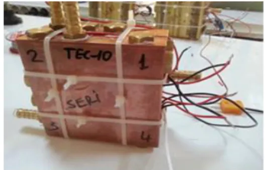
The connection of the 8 TEMs formed in the 2 of the blocks shown in Fig. 6 was performed as in Fig. 87. This connection method was preferred according to the current and voltage value of the load to be fed by the system.
Fig. 7. TEC1-12706 and TEC1-12710 parallel-connected image of
thermoelectric modules in the same block and serially connected image of thermoelectric module groups in two blocks.
2.3. Creation of Experimental Setup
In the experiments, hot water was passed through one of the plates in the blocks we formed with the two plates and cold water was passed through the other. TEMs were used as TEG and energy was obtained. The system was set up to work in 3 different flows with hot and cold closed water system Wilo brand RSL 15 / 5-3 ku-p model 80W combi motor.
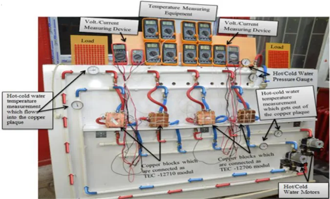
Fig. 8. The general structure of the designed system, the circulation of the water in the closed system and the appearance of the coper
In addition, both the temperatures of the hot and cold water circulating in the system before and after entering the copper material and the pressure of the system was measured by analog gauges mounted on the system. Figure 8 shows the general structure of the system, the circulation of water in the closed system and copper blocks connected to the system.
In the experiments, MY-64 digital-multimeter measuring instruments were used both in the heat-coldness measurements of the TEMs' surfaces and in the measurements of the voltages and currents it produces. In addition, 121 red wires of 10 mm loads were connected parallel to each other at the exit of the thermoelectric modules.
System's hot water: The water passing through the heat exchanger was heated by the heater source and circulated throughout the system. On the other hand, city water of an average of 19 °C temperature was pumped to the cold water system. However, the temperature of the hot water affected the temperature of the cold water and caused its temperature to increase due to the fact that the TEMs used were as thin as 3.8 mm and due to the closeness of the two plates through which hot and cold water pass. To prevent this situation, a propeller heat exchanger was used, and the temperature of the cold water could be kept at a certain level through the air. Thanks to the propeller heat exchanger, the temperature of the cold water was observed to fall even below the temperature of the city water in some experiments. The system is a closed system and connections were made so that the city water could be pumped from outside before each experiment. Thus, it became possible to adjust the pressure of the closed system as desired. Heat exchangers were used in the heating and cooling of the city water pumped to the closed system. The values were recorded every minute during the experiment. Experiments were carried out at 3 different pressures and at 3 different pressures and the energy and power produced by TEGs were observed. The duration of the experiment changed between 30 and 70 min. During this time, the temperatures on the plates reached about 100°C. In the experiments
conducted, the fact that about 83% of the geothermal energy in Turkey is at a low and medium temperature (30-100°C) and attention was paid not to exceed 100 °C. In the experiments (TH)
the module hot surface, (TC) the module cold surface, the voltage
(V) and current (A) values obtained from the geothermal energy were measured.
3. Findings
In this study, 9 experiments were conducted at 1-2.5 and 3.5 bars with the revolving speed motors in the 1st-2nd-3rd stages. The two types were observed by comparing the energy and the power they produce as the result of the operation of TEM as TEG. In the first three experiments, the hot/cold water pressure was kept constant at 1 bar and the motor speed was changed in 1st-2nd-3rd stages. Figure 9 shows the graphs of the powers produced by TEC1-12710 and TEC1-12706 TEMs as TEG in these three experiments.
(a) Graph (b) TEC1-12706 Bar 2.5 Motor (1st-2nd-3rd) Stage Power (W)
(b)
Fig. 9. (a) TEC1-12710 Bar 1 Motor (1st-2nd-3rd) Stage Power (W)
Graph (b) TEC1-12706 Bar 1 Motor (1st-2nd-3rd) Stage Power (W) Graph
As shown in Figure 10, in these operating conditions, while TEC1-12706 started to produce power at 300 °C, TEC1-12710 started to produce power at 450 °C. The highest power in the TEC1-12710 was achieved in the 2nd stage of the motor, while the highest power in the TEC1-12706 modules was obtained in the 3rd stage of the motor.
In the next 3 experiments, the hot/cold water pressure was kept constant at 2.5 bpm and the motor speed was changed at 1st-2nd-3rd stages. Figure 10 shows the comparison of the power produced by TEGs in these experiments. In these experiments, the highest power in both TEGs was obtained at motor speed 3.
(a)
(b)
Fig. 10. (a) TEC1-12710 Bar 2.5 Motor (1st-2nd-3rd) Stage Power (W)
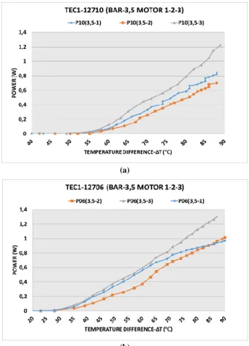
In the last 3 experiments, the motor speed was changed in 1-2-3 stages by keeping the hot/cold water pressure at 3,5 bars. Figure
11 shows the graphical results of power comparisons produced by TEGs in these experiments.
(a)
(b)
Fig. 11. (a) TEC1-12710 Bar 3.5 Motor (1st-2nd-3rd) Stage Power (W)
Graph (b) TEC1-12706 Bar 3.5 Motor (1st-2nd-3rd) Stage Power (W) Graph
In all the 9 tests conducted, the highest power from both TEGs was 2.5 at the motor speed of 3.
4. Discussion and Conclusion
This study is based on geothermal energy from renewable energy sources and the model is simulated with a thermoelectric generator which transforms the heat directly into electricity for the application of the system. Unlike the previous studies, this study compared the power generated at a temperature change from 10 °C to 90 °C by two different thermoelectric modules with an electrical connection type in water at different flow and pressure. So, many factors were combined, and the results were examined. The temperature range was determined considering that 83% of the geothermal resources in Turkey have a low and average temperature range. The experimental setup was established in the laboratory environment and a total of 9 experiments were carried out in hot/cold water pressure at 1-2,5 and 3,5 bar and motor speeds in the 1st, 2nd and 3rd stages. In the experimental setup, the heat required to create a temperature difference on the surface of the TEMs was obtained from an external source, while cooling was obtained by air cooling through a propeller-connected heat exchanger. The data was recorded every minute in the experiment and the currents and voltages produced by 12710 and TEC1-12706 thermoelectric modules as a result of temperature difference increasing every minute were also recorded. The temperatures of both hot and cold water circulating in the system were measured
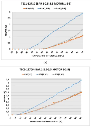
separately by analog meters before and after the water entered the copper plates. These measurements showed that there was a 1-2 °C difference between hot water entry and exit. So, the heat loss of the system on the plates was quite low. The highest powers produced by TEGs in the 3 experimental groups conducted in each of the 3 bars are compared in Fig. 12.
(a)
(b)
Fig. 12. (a) TEC1-12710 Bar (1-2,5-3,5) Motor (1st-2nd-3rd) Stage
Power (W) Graph (b) TEC1-12706 Bar 3.5 Motor (1st-2nd-3rd) Stage Power (W) Graph
Experiments conducted showed that the energy and power generated by the TEGs increased as the water pressure increased. At low pressure and flow, on the other hand, energy production fell considerably. It is seen that the hot/cold water flow has more effect on the system than the water pressure.
When two different TEMs are compared, it is observed that the TEC1-12706 thermoelectric module produces faster current and voltage at low temperatures. The LEDs which are connected as load started to draw current and light between 1,6 and 1,7 V. TEC1-12706 thermoelectric modules produced this current when the temperature difference on their surfaces was about 27-28 °C while TEC1-12710 thermoelectric modules were capable of producing this current when the temperature difference on their surfaces was about 33-36 °C. However, when the surface temperature differences in both thermoelectric modules rose above 50 °C, TEC1-12710 thermoelectric module is more powerful than TEC1-12706 thermoelectric module due to the voltage-current it generates. Thus, it is observed that TEC1-12706 TEM is better than 12710 TEM at low temperature differences, and TEC1-12710 TEM is better than TEC1-12706 TEM at high temperature differences. The experiments conducted shows that the temperature, the pressure and the flow of the thermal water source must be considered when choosing the type of TEMs.
ACKNOWLEDGMENT
This study was supported by Selçuk University Scientific Research Projects Unit with project number: 15401127.
References
[1] A.C. Ağaçayak, H. Çimen, S. Neşeli, and G. Yalçın. (2017, December). Two Different Peltier Run as Thermoelectic Generator and Comparison of Current, Voltage, Power Generation at Different Temperature. In Paper presented at the IRSEC17 5th International Renewable and Sustainable Energy Conference. Tangier, Morocco [Online]. Available: http://www.med-space.org/docs/IRSEC17-program.pdf
[2] A.C. Ağaçayak, H. Çimen, S. Neşeli, and G. Yalçın. Electricity Generation by Thermoelectric Generator. In Paper presented at the UMYOS 6th Internation Vocational School Symposium. Saray Bosna. 2017, pp. 541-548.
[3] R. Ahıska, H. Mamur, F. Korkmaz, İ. Topaloğlu, M.A. İçyer, A. Dönertaş and U. Şahin. (2012). "Comparison of Thermoelectric Generator Systems and Photovoltaic Systems in Energy Production. Project Based Mechatronics Training Workshop, MKT2012: 6. [4] R. Ahıska, H. Mamur, and M. Uliş. (2012). Low Power DC-DC Boost
Converter Application for Thermoelectric Generators. Project Based Mechatronics Training Workshop, MKT2012: 6.
[5] R. Ahiska, L.I. Nykyruy, G. Omer, and G.D. Mateik. “The Thermoelectric Solar Panels.” Journal of Vasyl Stefanyk Precarpathian National University, vo. 3, pp. 9-14, 2016.
[6] K. Atik, and R. Kayabaşı. “Generation of Electric Energy with Thermoelectric Generator by Using Geothermal Energy.” Machinery Technology Electronics Magazine, vol. 6, pp. 59-64. 2009.
[7] M.O. Cernaianu, C. Cirstea, and A. Gontean. "Ćuk converter employing indirect current control loop for TEG energy harvesting devices". In Design and Technology in Electronic Packaging (SIITME), 2012 IEEE 18th International Symposium. 2012. pp. 193-96.
[8] S. Dikilitaş. "Microcontroller Controlled Geothermal Thermoelectric Generator Design and Application," M.S. thesis, Gazi Univ., Ankara, Turkey, 2002.
[9] J. Eakburanawat. "Development of a thermoelectric battery-charger with microcontroller-based maximum power point tracking technique", Elsevier, vol.83, pp. 687-704. 2009.
[10] S. Fettah. "Experimental Analysis of Electric Energy Generation System of Waste Heat of Solid Oxide Fuel Cell", Başkent Univ., Ankara, Turkey, 2010.
[11] A.Y. Kaya. "Experimental Investigation of Heat - Operated Thermoelectric System in Exhaust Gas", Süleyman Demirel Univ., Isparta, Turkey, 2010.
[12] R.Y. Kim and J.S. Lai. (2008). "Aggregated modeling and control of a boost-buck cascade converter for maximum power point tracking of a thermoelectric generator." In Applied Power Electronics Conference and Exposition, APEC 2008. Twenty-Third Annual IEEE, pp.1754-60. [13] C.E. Kinsella, S.M. O’Shaughnessy, M.J. Deasy, Ma. Duffy, and A.J. Robinson. (2014). 'Battery charging considerations in small scale electricity generation from a thermoelectric module', Applied Energy, vol. 114, pp. 80-90.
[14] A.S. Kushch, J.C. Bass, S. Ghamaty, and N.B. Elsner. (2001). "Thermoelectric Development at Hi-Z Technology." In 20th International Conference on Thermoelectrics, pp. 422-30.
[15] C. Lertsatitthanakorn. (2007). "Electrical performance analysis and economic evaluation of combined biomass cook stove thermoelectric (BITE) generator", Bioresource Technology, vol.98, no. 8, pp. 1670-74.
Testing System for the Refinement of Electrical, Thermoelectrical and Thermal Parameters of Thermoelectric Generator", Gazi Univ., Ankara, Turkey, 2013.
[17] S. Maneewan, J. Hirunlabh, J. Khedari, B. Zeghmati, and S. Teekasap. (2005). 'Heat gain reduction by means of thermoelectric roof solar collector, Solar Energy', Elze, vol.78, pp. 495-503.
[18] C. Sungkyu, K. Nmajae, P. Soonseo, and K. Shiho."A coreless maximum power point tracking circuit of thermoelectric generators for battery charging systems." In Solid State Circuits Conference (A-SSCC), 2010 IEEE Asian, pp.1-4.
[19] İ. Temizer, C. İlkılıç, B. Tanyeri, and M. Cihan. " Effects of Thermoelectric Technology on Vehicle Systems", In Journal of Life Sciences, Batman Univ. International participated Science and Culture Symposium. vol. 1, no.1 Batman Univ., Batman, Turkey, 2012 [20] B.C. Woo, D.Y. Lee, H.W. Lee, and I.J. Kim. "Characteristic of
maximum power with temperature difference for thermoelectric generator." In Thermoelectrics, 2001. Proceedings ICT 2001. XX International Conference on, 2001. pp. 431-34. IEEE.
![Fig. 1. Thermoelectric module section appearance [11].](https://thumb-eu.123doks.com/thumbv2/9libnet/4885910.97064/2.892.466.804.329.558/fig-thermoelectric-module-section-appearance.webp)