Numerical investigation for convective heat transfer and
friction factor under pulsating flow conditions
Erman Aslan1,*, Mert Ozsaban2, Guven Ozcelik3, and Hasan Riza Guven1
1Mechanical Engineering Department, Istanbul University-Cerrahpasa, Avcilar Campus, 34320 Avcilar, Istanbul, Turkey 2Mechanical Engineering Department, Recep Tayyip Erdogan University, Zihni Derin Campus, 53100 Merkez, Rize, Turkey 3Mechanical Engineering Department, Istanbul Arel University, Tepekent Campus, 34537 Buyukcekmece, Istanbul, Turkey
Abstract. For pulsating flow, the behaviours of the convective heat transfer and friction factor for a
periodic corrugated channel are investigated numerically. The finite volume method is used in the numerical study. Three different Reynolds Averaged Numerical Simulation based turbulence models, namely the k-ω model, the Shear Stress Transport (SST) model and the transition SST model are used and compared. The results are also compared with the previous experiments for non-pulsating flow. Analyses are conducted for air flow through a corrugated channel which has sharp corrugation peaks with an inclination angle of 30° and a 5mm minimum channel height. Reynolds number is changed in the range 6294 to 7380, while keeping the Prandtl number constant at 0.70. A sinusoidal pulsatile flow condition which is F=400 and uA*=0.5 is
used. Variations of the Nusselt number and the friction factor with the Reynolds number are studied. Non-pulsating flow results and Non-pulsating flow results are compared with each other.
Nomenclature
Dh: hydraulic diameter, m f: friction factor, frequency 1/s F: nondimensionalized frequency H: channel height, mh: cycle average heat transfer coefficient, W/(m2K)
h: axially local heat transfer coefficient, W/(m2K)
k: thermal conductivity, W/(mK) Nu: Nusselt number
p: Pressure, Pa Re: Reynolds number
S: pitch (axial length of cycle), m T: temperature, K t: time, s u: velocity, m/s x: axial coordinate, m Greek symbols θ: contact angle, ° ρ: density, kg/m3 μ: dynamic viscosity, kg/(m.s) ν: kinematic viscosity, m2/s
Sub- and Superscripts: A: amplitude min: minimum max: maximum 0: uniform inlet *: nondimensionalized
1 Introduction
Lately, because of the increasing demand by industries including power generation [1] and heat recovery [2] for more efficient and compact exchangers [3, 4], exploration of heat transfer enhancement methods has gained great momentum. To this purpose, two techniques can generally be identified, namely, the active and passive techniques. Active techniques include surface vibration, fluid vibration, electrostatic fields, boundary layer injection, boundary layer suction, electro-hydrodynamics, etc. for increasing heat transfer. Thus, active techniques require more costs and attention.
In passive techniques, besides using fluid additives, the applied approaches generally involve a modification of the channel in a way to increase the heat transfer rate. A special category of heat transfer enhancement is the use of bluff bodies that increase heat transfer coefficient by turbulence generation and vortex shedding in their wake [5, 6]. A further category is the insertion of structures that interrupt the wall boundary layer and create recirculation and turbulence near the wall [7]. Passive methods may also include categorical changes in the flow arrangement, such as the use of jet impingement techniques [8, 9] instead of wall-congruent flow, which is, however, out of the present scope. Enhancement of the radiative heat transfer [10] is also not included in the present scope. The present focus is on the enhancement of heat transfer by forced convection. In the present investigation, a combination of passive and active techniques is considered. The use of corrugated channels
and pulsatile inlet flow conditions belong to the passive and active categories, respectively.
Experimental investigations of forced convection in corrugated channels were performed by Sparrow and Hossfeld [11], Snyder et al. [12], Bilen et al. [13] and Nilpueng and Wongwises [14], who investigated the velocity and temperature fields experimentally. Computational investigation of force forced convection in corrugated channel in turbulent regimes were also performed to get convective heat transfer coefficient and pressure drop by Ciafalo et al. [15], Mirzaei et al. [16].
Pulsating flows are encountered in many engineering applications and also in nature and biological systems. One of the engineering applications is pulsating flow in pipe and channels. Ray et al. [17] studied analytically and numerically to find development length of sinusoidally pulsating laminar pipe flows in moderate and high Reynolds number regimes. Hydrodynamics of piston-driven laminar pulsating flow for developing flow was studied numerically at Re=1000 by Aygun and Aydin [18]. Five different values of the frequencies were considered. They found that the friction coefficient increases with frequency. In second paper of Aygun and Aydın, hydrodynamics of piston-driven laminar pulsating flow for fully developed flow was investigated numerically, analytically and experimentally [19]. Again five different frequency values were determined like in first paper [18]. The near/off-wall flow reversals are at F=105, 226 and 402, where F is the non-dimensional frequency. Numerical studies of flow and heat transfer in circular tube under pulsating flow condition were carried out in the laminar regime by Chattopadhyay et al [20]. The frequency interval was taken from 0 to 20Hz, and amplitude was determined to be greater than one. It was observed that pulsation has no positive effect in augmenting heat transfer within the investigated range of pulsation frequency and amplitude. A computational investigation of the pulsating flow and heat transfer in a straight circular tube, for the turbulent flow regime was presented by Benim et al. [21], where no significant enhancement of the time-averaged heat transfer rate by pulsations was observed for the considered conditions.
A perturbation approach was used to obtain analytical analytical expression for the velocity and temperature distribution and transient Nusselt number for the problem of forced convection, in a parallel plates or a circular tube by Nield and Kuznetsov [22]. Pulsating flow conditions were formed via applied pressure gradient that fluctuates with small amplitude harmonically in time. It was observed that, Nusselt number alters with frequency. In another investigation, performance of closed-loop pulsating heat pipes with uniform and altering tube diameter was studied experimentally by Tseng et al. [23]. Metha and Khandekar [24] investigated heat transfer of single-phase pulsating laminar flow in a square mini-channel, experimentally. According to the results, heat transfer enhancement due to periodic pulsating flow depends on frequency. With increasing frequency, heat transfer rate increases. The effect on flow and heat transfer characteristics for pulsating laminar flow in a heated square cylinder was investigated numerically by Yu et al.
[25], where pulsation amplitude and frequency were changing in the range 0.2 - 0.8[-] and 0 - 20Hz, respectively. It was found [24] that when the pulsating frequency was about the natural vortex shedding frequency, heat transfer was also substantially enhanced. Convection heat transfer in a corrugated channel was investigated by Jafari et al. [26] for pulsating flow conditions using the Lattice Boltzmann Method. The dimensionless frequency of pulsating velocity and oscillating amplitude were studied at a wide range (Strouhal number, from 0.05 to 1, and amplitude, from 0 to 0.25, where amplitude is equal to “0” represents the steady flow). It was found that the best effect of flow pulsation on convection rate was achieved for a special value of the oscillation frequency, which was depending on the Reynolds number. Pulsating flows also occur in biological systems, such as the blood flow in human aorta under physiological, or surgery conditions, and have been investigated by different researchers [27].
In the present study, convective heat transfer and friction factor characteristics in a corrugated channel with pulsating flow conditions are investigated numerically using the finite volume method. Only one type corrugation geometry is used which has sharp corrugation peak. One sinusoidal flow condition is considered. Three different RANS based turbulence models, namely the k-ω, the Shear Stress Transport (SST) and the transition SST, are used.
2 Problem definition
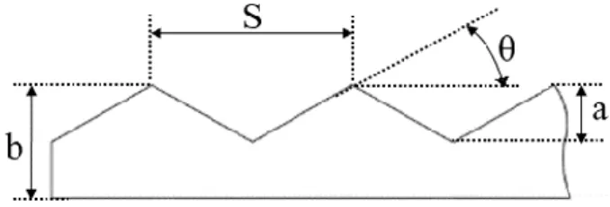
A symmetrically corrugated channel with sharp corrugation peaks is considered. The schematic of channel with the geometry parameters is shown in Figure 1. Contact angle (θ) is 30°, pitch or axial length of cycle (S) is 17.32mm, channel half height (b) is 7.5mm and height of corrugation (a) is 5mm.
Fig. 1. Schematic figure of corrugation channel with the
representative parameters.
According to these parameters maximum channel height is defined as;
max 2
H b (1)
while the minimum channel height is given by;
min 2
H b a (2)
The hydraulic diameter is defined as;
min max
h
In the numerical study, Reynolds number (Re) is varied from 6294 to 7380, and Prandtl number is 0.7.
In the numerical calculatios, the flow and heat transfer were assumed to be two-dimensional. Material properties of air are assumed to be constant. Figure 2 shows a schematic of typical solution domain with boundary types. At the inlet, a sinuosidial velocity profile in time is applied for getting pulsating flow conditions. Sinusodial velocity profile is defined as;
*
0 1 Asin 2
u t u u
ft (4) where u is the uniform inlet velocity, f is frequency, 0t is time and *
A
u is nondimensionalized amplitude. The nondimensionalized amplitude is defined as;
* 0 A A u u u (5)
where u is amplitude. Nondimensionalized frequency A F is defined as; 2 h D f F
(6)where
is the kinematic viscosity. The Reynolds number is defined as0
Re
u Dh
(7)
where is density and is dynamic viscosity. One sinusoidal pulsating flow condition which is F=400, uA*=0.5 solved numerically.
An outflow boundary condition is imposed at the outlet for the momentum equations. No-slip boundary condition is applied at walls. For the energy equation, constant temperature (300K) is imposed at the inlet. A constant heat flux (616 W/m2) is applied at the walls.
Zero temperature gradient is used at the outlet.
3 Modelling and Assumptions
The time-dependent incompressible Navier-Stokes equations coupled with the continuity equation, the energy equation and the turbulence model equations are solved using the finite volume based commercial CFD code Ansys-Fluent [28]. For turbulence modelling, three models, namely the k-ω model [29], the SST model [30] and the transition SST model [31] are employed. For modelling, the near-wall turbulence model, no wall functions approach [32] is used. The applied turbulence equations are capable of representing the near-wall turbulence, provided that the grid resolution is sufficiently fine.
For discretizing convective terms a second-order upwinding procedure is used [28]. A second-order implicit scheme is used for integration in time [28]. For pressure velocity coupling PISO algorithm is used [28].
Default under-relaxation factors (pressure: 0.3, momentum: 0.7, turbulence quantities: 0.8 and energy: 1.0) are used [28]. As the converge criteria, a residual value 10-6 is required for all equations except energy
equations. For energy equation, residual value 10-8 is
used. At the inlet boundary, the turbulence intensity is kept at 4% and the length scale was assumed to be one third of the hydraulic diameter.
A structured meshing strategy based on quadrilateral finite volumes is used. A grid independence study is performed for finding an adequate grid resolution for all turbulence models. The Nusselt number and the friction factor are taken as the quantities to be monitored. The grid independence study was performed for steady-state flow conditions. Doing so, the maximum temporal flow rate of the pulsating flow is assumed to be the flow rate in the steady-state. This means that the velocity
max 0 A
u u u , is prescribed at the inlet, where u0 is
taken from the maximum Reynolds number. In order to cope with the requirements of turbulence models for modelling the near-wall turbulence, without using wall-functions, an all grids, it is ensured that the distance of first near-wall cell fulfill the condition of y1 and at least three cells are contained in the region for y5. For all turbulence models, and four cases, the grid independence mesh number is 192000. In the unsteady calculation, time step size has been chosen in such a way that the cell Courant number takes a value about unity.
Two parameters of interest for the present study are (1) Nusselt number, (2) friction factor. In numerical calculations, cycle averaged Nusselt number is calculated as h hD Nu k (8)
where h is the cycle averaged heat transfer coefficient and k is the thermal conductivity. In numerical calculations, firstly, local heat transfer coefficients (h ) x at the previous three cycles are calculated with using the wall and fluid time-averaged temperatures. Finally, the cycle averaged heat transfer coefficient is obtained using the local heat transfer coefficients.
3 0 1 3 S x h h dx S
(9)In numerical simulations, two sections are specified for calculating the pressure gradient (dP dx). The first section is placed at the beginning of the previous three cycles from the last cycle. Second section is located on the end of the previous cycle from the last cycle. Friction factor is calculated using pressure gradient as.
2 0 1 2 h dP f D u dx
(10)4 Results
Figure 2 shows the axial velocity distribution predicted by (a) k-ω, (b) SST and (c) transition SST turbulence model. These predictions are obtained for the highest Reynolds number (Re=7380), for F=400 and uA*=0.5
The flow develops through the channel and the flow characteristics are observed to reach a certain periodicity for the last cycles of the corrugated channels for three turbulence models. Therefore, one can say that the flow is rather fully developed, in this sense, for the last cycles of the channel. For the lower Reynolds number, the flow is observed to reach the fully-developed state earlier.
The displayed plots show the velocity distribution in the cycle before the last, where the velocity field can be assumed to be fully developed. In all predictions, a jet-like forward flow in the central region can be observed, which is surrounded by a recirculation zone.
The predictions of the three turbulence models are qualitatively almost the same. Still, some differences can be observed. One can see that the positive axial velocities in the central region are predicted to be larger by the k-ω model, in comparison to the predictions of the other turbulence models. The transition SST model predicts the lowest values of the axial velocity in the central region, whereas the prediction of the SST model is in between (Fig. 2).
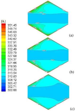
The predicted time-averaged temperature distribution by (a) k-ω, (b) SST and (c) transition SST turbulence model is shown in Figure 3 for the highest Reynolds number (Re=7380) for F=400 and uA*=0.5. The
displayed cycle in Figure 3 is the same as the one in Figure 2, i.e. the second form the last.
The flow is gradually and continuously heated up through the channel by the applied constant heat flux at the wall. It is clearly seen in Figure 2, that the onset and the growth of the circulation zones promote the mixing of cold fluid from the core with the hot fluid near to the boundary layer. This induces higher temperature gradients near the corrugated walls. Thus, the net heat transfer rate from the corrugated wall to the fluids get enhanced. The k-ω turbulence model produce higher temperature is than the other turbulence models, where the temperature increase is smallest for the transitional SST model.
Figure 4 shows the relationship between the Nusselt and Reynolds numbers for the F=400 and uA*=0.5. The
curves predicted by the three turbulence models are compared with each other and with the experimental results for the non-pulsating conditions [33]. One can see that Nu increases for increasing Re, In SST and transition SST turbulence models, the experimental steady-state Nu is lower than for pulsating case. In a previous study [33], the SST model, was found to perform better than other turbulence models. A superior performance of the SST model in predicting convective heat transfer was also observed by other authors [34, 35]. Therefore, we can say that pulsating flow enhances the convective heat transfer.
(a)
(b)
(c)
Fig. 2. Time-averaged axial velocity [m/s] contours for (a) k-ω,
(b) SST, (c) transition SST.
(a)
(b)
(c)
Fig. 3. Time-averaged temperature [K] contours for (a) k-ω,
Fig. 4. Nusselt number as function of Re, for F=400, uA*=0.5.
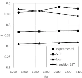
Figure 5 shows the relationship between the friction factor and Reynolds number for the F=400 and uA*=0.5.
One can see that f has an increasing trend with increasing Re, except for the transition SST model. Again, SST model was predicting the best results than the other turbulence models, according to previous study [33]. Friction factor prediction of the SST model is lower than experimental results which is get from non-pulsating flow. Thus, we can say that, with using pulsating flow conditions friction factor decreases.
Fig. 5. Friction factor as function of Re, for F=400, uA*=0.5.
5 Conclusions
The present paper presents a computational study for a corrugated channel under pulsating flow conditions. One pulsating flow condition, which is F=400 and uA*=0.5, is
applied. The pulsating numerical results are compared with each other, and the non-pulsating experimental results [33]. Three turbulence modes are used, namely, the k-ω model, the SST model and the transition SST model. The major conclusions to be drawn are:
Pulsating flow condition have a positive effect to enhance heat transfer.
Nusselt number increases with increasing Reynolds number.
The SST and transition SST turbulence models produce the highest Nusselt numbers, which are also higher than the non-pulsating experimental results. However, the k-ω turbulence model produces the lowest Nusselt numbers that are also lower than the non-pulsating experimental results Pulsation decreases the friction factor.
Friction factor increases with increasing Reynolds number for the k-ω and SST turbulence models. However, for the transitional SST turbulence model friction factor decreases with increasing Reynolds number.
In the future work, the new pulsating cases will be investigated for understanding the amplitude and frequency effects of Nusselt number and friction factor, and for validating the numerical results.
References
1. P. Oclon, S. Lopata, M. Nowak, A.C. Benim, Progress in Computational Fluid Dynamics 15, 5, pp. 290-306 (2015)
2. D.G. Ebling, A. Krumm, B. Pfeiffelmann, J. Gottschald, J. Bruchmann, A.C. Benim, M. Adam, R. Labs, R. R. Herberz, A. Stunz, Journal of Electric Materials 45, 7, pp. 3433-3439 (2016)
3. A. Jokar, S.J. Eckels, M.H. Hosni, Heat Transfer Engineering 31, 1, pp. 3-16 (2010)
4. A.M. Maqableh, A.F. Khadrawi, M.A. Al-Nimr,, S.A. Ammourah, A.C. Benim, Progress in Computational Fluid Dynamics 11, 5, pp. 318-328 (2011)
5. A.C. Benim, H. Chattopadhyay, A. Nahavandi, International Journal of Thermal Sciences 50, 10, pp. 1973-1983 (2011)
6. I. Taymaz, E. Aslan, A.C. Benim, Thermal Science 19, 2, pp. 537-547 (2015)
7. S. Bhattacharyya, H. Chattopadhyay, A. Guin, A.C. Benim, Heat Transfer Engineering, published online, doi: 10.1080/01457632.2018.1474593 (2018) 8. H. Chattopadhyay, A.C. Benim, Journal of Heat
Transfer – Transactions of the ASME 133, 10, Article No: 104502, doi:10.1115/1.4004075 (2011) 9. S.D. Farahani, F. Kowsary, Heat Transfer
Engineering 39, 10, pp. 901-913 (2018)
10. A.C. Benim, Computer Methods in Applied Mechanics and Engineering 67, 1, pp. 1-14 (1988) 11. E.M. Sparrow, L.M. Hossfeld, Int. J. Heat Mass
Trans. 27, pp. 1715-1723 (1984)
12. B. Snyder, K.T. Li, R.A. Wirtz, Int. J. Heat Mass Trans., 36, pp. 2965-2976 (1993)
13. K. Bilen, M. Cetin, H. Gul, T. Balta, Appl. Thermal Eng. 29, pp. 753-761 (2009)
14. K. Nilpueng, S. Wongwises, Exp. Thermal Fluid Sci. 15, pp. 290-306 (2006)
15. M. Ciofalo, J. Stasiek, M.W. Collins, In: Proc. 2nd Int. Symp. Eng. Turbulence Modelling and Measurements (Florence, Italy, pp. 293-292, 1993) 16. M. Mirzaei, A. Sohankar, L. Davidson, F. Innings,
Int. J. Heat Mass Trans. 76, pp. 432-446 (2014) 17. S. Ray, B. Unsal, F. Durst, Int. J. Heat Fluid Flow
37, pp. 167-176 (2012)
18. C. Aygun, O. Aydin, Nucl. Eng. Design 274, pp. 164-171 (2014)
19. C. Aygun, O. Aydin, Nucl. Eng. Design 274, pp. 172-180 (2014)
20. H. Chattopadhyay, F. Durst, S. Ray, Int. Com. Heat Mass Transfer 33, pp. 475-481 (2006)
21. A.C. Benim, M. Cagan, D. Gunes, Int. J. of Thermal Sciences 43, 8, pp. 725-732 (2004)
22. D.A. Nield, A.V. Kuznetsov, Int. J. Thermal Sciences 46, pp. 551-560 (2007)
23. C.Y. Tseng, K.S. Yang, K.H. Chien, M.S. Jeng, C.C. Wang, Exp. Therm. Fluid Sciences 54, pp. 85-92 (2014)
24. B. Metha, S. Khandekar, Int. J. Thermal Sci. 91, pp. 157-166 (2015)
25. J.Y. Yu, W. Lin, X.T. Zhen, Heat Mass Trans. 50, pp. 849-864 (2014)
26. M. Jafari, M. Farhadi, K. Sedighi, Int. Commun. Heat Mass. Trans. 45, pp. 146-154 (2013)
27. A. Assmann, A.C. Benim, F. Gül, P. Lux, P. Akhyari, U. Boeken, F. Joos, P. Feindt, A. Lichtenberg, Journal of Biomechanics 45, 1, pp. 156-163 (2012) 28. Ansys Fluent 14.5 User’s Guide (Ansys Inc.,
Canonsburg, PA , 2012)
29. D.C. Wilcox, Turbulence Modelling for CFD (DCW Industries, Inc., La Canada, California, 1988) 30. F.R. Menter, AIAA Journal 32, pp. 1598-1605
(1994)
31. F.R. Menter, R. Langtry, S. Volker, Flow Turbulence Combustion 77, pp. 277-303 (2006)
32. P.A. Durbin, B.A. P. Reif, Statistical Theory and Modelling for Turbulent Flows, 2nd ed. (Wiley,
Chichester, 2011)
33. E. Aslan, I. Taymaz, Y. Islamoglu, M. Engin, I. Colpan, G. Karabas, G. Ozcelik, Progress in Computational Fluid Dynamics 18, 1, pp. 33-45 (2018)
34. A.C. Benim, D. Brillert, M. Cagan, ASME Paper No. GT2004-54151, in: Proc. ASME Turbo Expo 2004, Vienna, Austria, June 14-17, 2004, Vol. 4, pp. 453-460, doi:10.1115/GT2004-54151 (2004) 35. A.C. Benim, K. Ozkan, M. Cagan, D. Gunes,
International Journal of Numerical Methods for Heat & Fluid Flow, 17, 3, pp. 284-301 (2007)