Journal of Micromechanics and Microengineering
PAPER
Rapid fabrication of microfluidic PDMS devices
from reusable PDMS molds using laser ablation
To cite this article: Ziya Isiksacan et al 2016 J. Micromech. Microeng. 26 035008
View the article online for updates and enhancements.
Related content
Rapid cell-patterning and microfluidic chip fabrication on glass
Meng-Hua Yen, Ji-Yen Cheng, Cheng-Wey Wei et al.
-Rapid fabrication of microfluidic chips based on the simplest LED lithography
Yue Li, Ping Wu, Zhaofeng Luo et al.
-Printing-based fabrication method using sacrificial paper substrates for flexible and wearable microfluidic devices
Daehan Chung and Bonnie L Gray
-Recent citations
Rapid prototyping of flexible multilayer microfluidic devices using polyester sealing film
Yiqiang Fan et al
-A fast and low-cost microfabrication approach for six types of thermoplastic substrates with reduced feature size and minimized bulges using sacrificial layer assisted laser engraving
Longjun Gu et al
-Hybrid polymer composite membrane for an electromagnetic (EM) valveless micropump
Muzalifah Mohd Said et al
1. Introduction
Microfluidics, the study and manipulation of fluids in micrometer scale structures, provides promising platforms for chemical and biological experimentation for lab-on-a-chip applications [1]. Polydimethylsiloxane (PDMS) is com-monly used for microfluidic devices because it is optically transparent and biocompatible. Soft lithography is the most preferred method for the fabrication of PDMS devices [2]. This method employs a mold that can be used multiple times for device fabrication. In order to get the desired device pat-terns on the PDMS layer, one should fabricate the mold, cast
PDMS onto the mold, cure PDMS, and peel off the PDMS layer. Then, the device fabrication is completed by punching the inlet/outlet holes and bonding to another surface.
UV photolithography provides down to 1 μm feature
resolution for molds used for soft lithography [3]. However, fabrication of the mold requires cleanroom processes that are expensive, time-consuming, and labour intensive. Also, commonly used SU-8/silicon molds are fragile and prone to delamination [4]. It is therefore of critical importance to develop alternative rapid prototyping methods. Direct writing of PMMA and PDMS via laser ablation has been previously demonstrated [5–9]. In these studies, bulges, splashes, and
Ziya Isiksacan , M Tahsin Guler , Berkan Aydogdu , Ismail Bilican and Caglar Elbuken1
1 UNAM—National Nanotechnology Research Center, Institute of Materials Science and Nanotechnology, Bilkent University, 06800 Ankara, Turkey
2 Department of Physics, Kirikkale University, 71450 Kirikkale, Turkey
3 Science and Technology Application and Research Center, Aksaray University, 68100 Aksaray, Turkey E-mail: [email protected]
Received 15 November 2015, revised 28 December 2015 Accepted for publication 7 January 2016
Published 3 February 2016 Abstract
The conventional fabrication methods for microfluidic devices require cleanroom processes that are costly and time-consuming. We present a novel, facile, and low-cost method for rapid fabrication of polydimethylsiloxane (PDMS) molds and devices. The method consists of three main fabrication steps: female mold (FM), male mold (MM), and chip fabrication. We use a CO2 laser cutter to pattern a thin, spin-coated PDMS layer for FM fabrication. We then obtain
reusable PDMS MM from the FM using PDMS/PDMS casting. Finally, a second casting step is used to replicate PDMS devices from the MM. Demolding of one PDMS layer from another is carried out without any potentially hazardous chemical surface treatment. We have successfully demonstrated that this novel method allows fabrication of microfluidic molds and devices with precise dimensions (thickness, width, length) using a single material, PDMS, which is very common across microfluidic laboratories. The whole process, from idea to device testing, can be completed in 1.5 h in a standard laboratory.
Keywords: microfabrication, microfluidics, rapid prototyping, laser ablation, microdroplet generation
S Online supplementary data available from stacks.iop.org/JMM/26/035008/mmedia
(Some figures may appear in colour only in the online journal) Z Isiksacan et al Printed in the UK 035008 JMM 0960-1317 10.1088/0960-1317/26/3/035008
Paper
3Z Isiksacan et al
2
resolidification of ablated material cause distorted sidewalls and bonding issues. Also, the channel height is dependent on laser parameters that are prone to change over long runs. Additionally, in direct writing, the whole process must be repeated each time from scratch to get a new device. To address the shortcomings of direct writing and fragility of silicon molds, elastomer (PDMS) and plastic molds have been fabricated using replica molding [4, 10]. However, these molds require cleanroom-fabricated silicon molds to start with. Also, for PDMS molds, adhesion occurs during PDMS/ PDMS casting [11, 12]. To prevent adhesion, several chemical surface treatments have been demonstrated with potentially hazardous chemicals [13–16].
In this study, we introduce a novel rapid fabrication method to fabricate PDMS microfluidic molds and devices. We can obtain channels with precise dimensions and vertical side walls, which enables this method to be an alternative for clean-room-dependent fabrication methods. This method provides significant time and cost savings especially when several design iterations are required. The method has three main steps. In the first step, we fabricate the female mold (FM) by patterning a thin spin-coated PDMS layer using a CO2 laser cutter. We can
precisely control the thickness of the PDMS layer through spin coating settings, which in turn determines the channel height. In the second step, we obtain the reusable PDMS male mold (MM) from the FM by replica molding. This MM replaces the silicon mold in soft lithography. Finally, we obtain PDMS devices from the reusable MM by PDMS/PDMS casting.
We have demonstrated that demolding of PDMS devices from a PDMS mold can simply be performed by applying a drop of silicone oil between the PDMS layers and by carefully setting the curing time and temperature. To demonstrate the longevity of the reusable PDMS MM, we compared the first and the tenth replicas obtained from the same mold. Also, in order to demonstrate the versatility of the method, we fabri-cated a T-junction microfluidic device and showed formation of monodisperse water-in-oil microdroplets.
2. Materials and methods
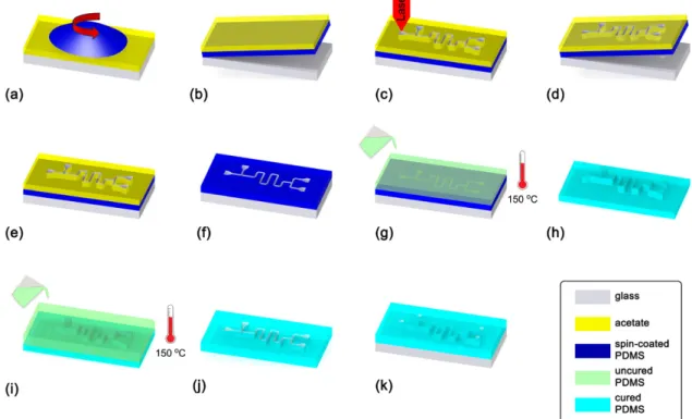
The rapid fabrication process of PDMS microfluidic devices is schematically summarized in figure 1. One of the key benefits of this method is that both the FM and the MM are fabricated from PDMS (Sylgard 184, Dow Corning), which is a standard material used in microfluidic laboratories. The fabrication process consists of three main steps: (i) FM fabri-cation using laser ablation, (ii) MM fabrifabri-cation using PDMS/ PDMS casting, and (iii) device fabrication using PDMS/ PDMS casting.
2.1. Fabrication of the female mold
For the fabrication of the FM, firstly, a 150 μm thick acetate
sheet is taped on a glass slide. Then, PDMS (prepared at 10 : 1 ratio, debubbled) is spin-coated on the acetate sheet (figure 1(a)). The thickness of the PDMS layer can be precisely controlled
Figure 1. Rapid fabrication process flow for PDMS microfluidic devices. (a) PDMS is spin-coated on a 150 μm thick acetate sheet. (b) The PDMS/acetate layers are flipped over on the glass slide. (c) The PDMS/acetate layers are patterned by laser ablation. (d) The glass slide is discarded, and the PDMS/acetate layers are washed with DI. (e) The PDMS/acetate layers are plasma-bonded on a glass slide. (f ) The acetate layer is peeled off to form the female mold. (g) PDMS is cast on the female mold and cured for 2 min at 150 °C. (h) The top PDMS layer is peeled off to form the male mold. (i) PDMS is cast on the male mold and cured for 2 min at 150 °C. ( j) The top PDMS layer is peeled off to form the chip. (k) The inlet/outlet holes are punched, and the chip is plasma-bonded on a glass slide to form the microfluidic device.
18, 19]. These leftover pieces deteriorate the molding process in the subsequent steps. To avoid such issues, it is important to protect the surface of the spin-coated PDMS layer. Hence, we form the glass/PDMS/acetate structure before laser abla-tion. The acetate layer protects the PDMS surface whereas the glass slide provides the structural support. A comparison of the laser ablation results with and without the acetate layer is provided in the supplementary data file.
We use a 30 W CO2 laser (Epilog, Zing) to transfer the
desired patterns onto the FM. Most laser cutters have two operation modes: raster and vector. We have found that the vector mode results in less debris formation and smoother channel sidewalls, thus provides better ablation performance for PDMS. The power, frequency, and speed of the laser cutter are set as 6 W, 1000 Hz, and 2.5 cm s−1, respectively. During
the optimization of the laser parameters, we have scanned a range of values for these parameters and evaluated the out-come in terms of the channel sidewall profile, the precision of channel width, and the amount of debris formed. We have seen that laser power less than 4.5 W does not ablate the PDMS/ acetate layers. If the laser power is above 6.5 W, it burns the PDMS layer and leaves ash on the surface. The device pat-terns are designed in 2D using a CAD software (Autodesk, AutoCAD 2015). The channel width is defined by both the 2D drawing and the laser spot size. The focused spot size of the laser beam for our system is 120 μm. If the desired channel
width is smaller than 120 μm, the spot size can be reduced by
additional commercial or custom-made optical comp onents [20, 21]. In case the desired channel width is larger than 120 μm, the laser can be traced along the channel walls.
During channel fabrication by laser ablation, the laser beam ablates the channel intersection points more than once. In con-ventional laser writing techniques, this causes over ablation and results in a deeper channel at the channel junction as seen in several studies in the literature [9, 22]. On the other hand, we are making a through cut on the thin, spin-coated PDMS layer by laser ablation. Therefore, even though the same loca-tion is traced by the laser beam multiple times, the ablated thickness does not vary. This method allows very precise control of channel dimensions as opposed to the previously demonstrated laser-ablated devices.
The formation of glass/PDMS/acetate structure is also of importance to provide the draft angle required during the
subsequent casting steps. The side view of the laser ablation step (figure 1(c)) is shown in figure 2(a). The laser beam is focused on the glass slide so that the enlarging beam waist provides the draft angle. This tapered laser cut is the signature for laser ablation [7, 9]. When the laser-ablated PDMS layer is bonded to a separate glass slide (figures 1(e) and 2(b)), the orientation of the PDMS layer should be kept the same to have a positive draft angle. This ensures high replication fidelity for micrometer size channel designs.
Following the laser ablation step, the PDMS/acetate structure is peeled off from the glass slide and washed with deionized water to remove the debris originated from the laser-cutting step figure 1(d). Then, the laser-ablated PDMS layer is bonded to another glass slide with plasma activation figure 1(e). After plasma bonding, the acetate sheet is peeled off from the PDMS layer to form the FM figure 1(f). This FM is to be used for PDMS/PDMS casting to form the MM.
2.2. Fabrication of the reusable male mold
The second step in the fabrication process is the casting of the reusable PDMS MM. PDMS/PDMS double casting has been previously demonstrated in the literature [14, 23, 24]. However, for successful demolding, these studies require sur-face treatment using various chemicals [12, 14, 15, 25, 26]. Instead, we demonstrate that PDMS layers can simply be demolded from the bottom PDMS layer by applying silicone oil between the layers and suitably setting the curing time and temperature. Oil is absorbed by the bottom PDMS layer and prevents the adhesion of the PDMS layers, allowing facile release of one from the other without any deformation.
We start off by putting the FM in an aluminum pan with the laser-ablated PDMS layer facing up. Then, 100 μl silicone
oil was dispensed over the PDMS using a pipette. 100 μl was
enough for all the designs that we have used during this study.
Figure 2. Schematic representation of the formation of the draft angle with laser ablation. (a) The PDMS/acetate layers are patterned by laser ablation figure 1(c). (b) The patterned layers are plasma-bonded on a glass slide figure 1(e), which forms a positive draft angle. (c) PDMS is cast on the FM figure 1(g). (d) The cured PDMS layer is peeled off figure 1(h). The draft allows easier peeling-off.
Z Isiksacan et al
4
If the footprint of the chip is larger, more silicone oil can be dispensed so that all the recessed part in the FM is wet by oil. The excess amount of silicone oil spreads throughout the top layer. It is advised to cover the whole surface of the mold by oil. We wait for 1 min for the PDMS layer to absorb the silicone oil. Upon absorption, the excess oil is cleaned off the channels and the surface using an air gun. Then, the pan is placed on the hotplate for 5 min at 150 °C. While the pan is on the hotplate, PDMS (prepared at 10 : 1 ratio, debubbled) is poured on the FM figure 1(g). After 2 min, the pan is taken off the hotplate and cooled down to room temperature. It is crit-ical to ensure that PDMS is hardened before taking the pan off the hotplate. Our experiments have demonstrated that it takes 2 min to harden 1-cm thick PDMS at 150 °C. Then, the PDMS MM is gently peeled off from the FM, and the negative copy of the desired device pattern is obtained as MM figure 1(h).
2.3. Fabrication of the chip
The MM obtained in the previous step can be used multiple times for chip fabrication. In order to fabricate the chip, we put the MM in an aluminum pan. Then, the pan is placed on the hotplate for 5 min at 150 °C. While the pan is on the hot-plate, PDMS (prepared at 10 : 1 ratio, debubbled) is poured on the MM figure 1(i). After 2 min, the pan is taken off the hot-plate and cooled down to room temperature. Then, the PDMS chip is gently peeled off from the MM figure 1(j). Finally, the inlet/outlet holes are punched, and the PDMS chip is bonded to a glass slide with plasma activation figure 1(k).
3. Results and discussion 3.1. Fabrication of a model device
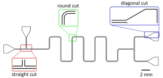
To demonstrate the functionality of this method, we have designed a model T-junction droplet generator and sorter microfluidic device as shown in figure 3. The channel width was drawn as 300 μm. First, FM has been fabricated using the
parameters given in the experimental section. It is important to note that when the vector laser-cutting mode is used, the laser
beam traces the channel walls throughout the design. Since the focused laser beam has a diameter of 120 μm, the final
channel width obtained on the FM is higher than the designed width. In our case, we have measured the channel width as 450 μm. On the other hand, the channel depth is solely
con-trolled by the spin-coating parameters of the PDMS layer that is patterned by the laser. When 10 : 1 mixed PDMS is spin-coated at a rate of 2000 rpm for 30 s, the PDMS thickness is 35 μm. After we fabricate the FM, we have obtained a
reus-able MM from the FM, and a chip from the MM, respectively. We have defined three regions of interest on the model device to investigate the channel wall profile and the replica-tion fidelity. The selected regions are composed of a straight, round, and diagonal cut channel segments. Figure 4 shows the final fabricated device.
Figure 5 shows the SEM images of these three regions of interest in the FM, MM, and chip. It should be noted that the laser cutter moves in stepwise motion in 2D plane. For this reason, round and diagonal patterns cannot be obtained as smooth as straight patterns. This results in around 5 μm
roughness at the sidewalls. It should also be noted that the roughness of the channel sidewalls depends on the resolution
Figure 3. Schematic representation of the model microfluidic device designed on a CAD software (Autodesk, AutoCAD 2015). Three selected regions of interest are straight cut, round cut, and diagonal cut channel segments.
Figure 4. Image of the microfluidic device fabricated with the presented rapid fabrication method. The device is a T-junction droplet generator and sorter.
Figure 5. SEM images of the selected regions of the fabricated FM, MM, and chip. The first, second, and third rows give the images of the straight, round and diagonal cut regions, respectively. The left, middle, and right columns are the images of the FM, MM, and chip, respectively. The SEM images of the MM (a2, b2, c2) are mirrored for ease of comparison.
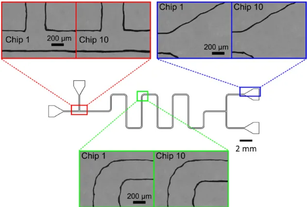
Figure 6. Optical microscope images of the selected regions of the first and tenth chips obtained from the same PDMS reusable MM. The comparison demonstrates that the fidelity performance of the method is very good.
Z Isiksacan et al
6
of the laser cutter. For the laser parameters (speed and fre-quency) that we set, the roughness at the straight channel is around 1 μm. Two critical observations are made here. First,
SEM images of the FM (figures 5(a1), (b1) and (c1)) prove that we can successfully obtain the desired vertical channel sidewalls throughout the device. We are able to ablate a thin PDMS layer without facing any of the laser ablation issues mentioned in the literature [9, 18]. Second, it is clear that both the MM and the chip replicate very well from the FM and the MM, respectively. These results show that PDMS/PDMS casting and demolding using silicone oil work successfully.
3.2. PDMS/PDMS replication fidelity
The main benefit of the SU-8 master molds fabricated using UV photolithography is their reusability. Therefore, it is important to evaluate the reusability of the molds produced by alternative fabrication methods. To demonstrate the rep-lication fidelity of our method, we have obtained ten chips using the same PDMS MM. Figure 6 shows the optical micro-scope images of the previously discussed straight, round and diagonal sections of the first and the tenth chips. When we compare the channel dimensions for these two chips, we can see that the channel width varies less than 1%. This demon-strates that the very same MM can be used many times to get PDMS chips without any deformation.
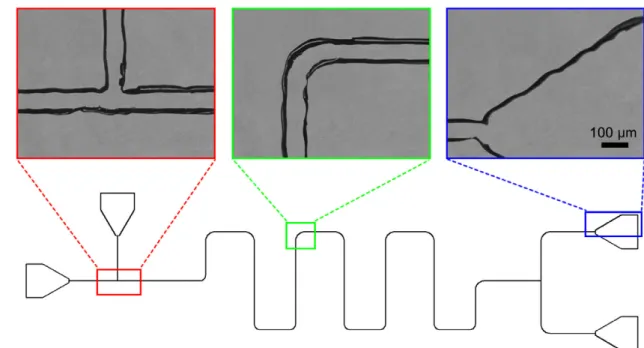
Using the same fabrication method, we have also fabricated the same channel geometry with the smallest possible channel width, which is 120 μm for our system. In this case, the CAD
drawing of the design is modified, and the FM was formed by a single trace of laser beam. The 2D CAD drawing and the optical images of the chip are shown in figure 7. As seen, the channel width is approximately 120 μm; straight, round and
diagonal cuts can be formed successfully. More importantly, the channel depth is the same throughout the design, since it
is dictated solely by the thickness of the PDMS spin-coated at the beginning of the fabrication. For the other laser abla-tion based methods, the juncabla-tion regions, where two channels meet, have a higher depth since it is traced twice by the laser beam [9, 22]. On the other hand, our fabrication method com-pletely alleviates this problem.
3.3. Microdroplet generation using the model device
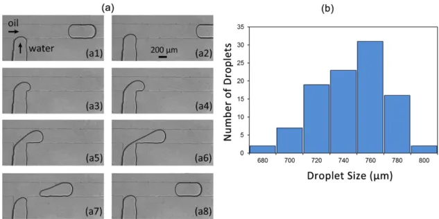
To show the versatility of our fabrication method, we have generated monodisperse water droplets in silicone oil (μ = 100 mPa s, Ultrakim) using a T-junction microfluidic
device with the design shown in figure 3. The inlet pressures for the oil and water were controlled using a pressure pump system (Elveflow OB1, 2 bar). Figure 8(a) shows the succes-sive images of the formation of a water droplet, when the inlet pressures were set to 15 mbar for oil and 12 mbar for water inlets. At these pressures, the flow rates for oil and water were 0.0165 μl min−1 and 0.006 μl min−1, respectively. The droplet
formation takes place in the squeezing regime [27, 28]. To analyze the size distribution of the generated water drop-lets, the length (front to end) of 100 subsequently generated droplets were measured using image processing (MathWorks, Matlab R2014). Figure 8(b) shows the histogram of the droplet sizes that yield a Gaussian distribution. The coefficient of variation for droplet size, which is defined as the ratio of standard deviation to mean, is calculated as 0.0346. This value is in accordance with the droplet monodispersity values for T-junction droplet generators in the literature [29, 30].
A wide range of microfluidic devices can be fabricated using our rapid fabrication method. We would like to empha-size that for any microfluidic device fabrication, the whole process, from idea to device testing, can be completed in 1.5 h as summarized in figure 9. In addition, the process does not require any complicated equipment and can be easily
Figure 7. Optical microscope images of the selected regions of the chip with the smallest possible channel width, 120 μm. The chip is obtained from a FM formed by a single trace of laser beam.
performed by a non-expert. The only limitation of this method is that the smallest channel width that can be obtained is deter-mined by the spot size of the laser beam. Therefore, if the required channel width is smaller than the laser spot size of commercial laser cutter systems, additional optical comp-onents may be needed.
4. Conclusion
In this study, we have presented a facile and low-cost method for rapid fabrication of PDMS devices. We have used a laser cutter to pattern the channel design on a spin-coated PDMS
layer. Then, using two successive PDMS/PDMS casting steps, we have obtained the microfluidic devices. PDMS/PDMS casting can be performed without any chemical surface treat-ment. Once the MM is fabricated, it can be reused for chip fabrication similar to the silicon/SU-8 molds used in conven-tional soft lithography. To demonstrate the funcconven-tionality of the method, we fabricated a model T-junction microdroplet generator device. The entire fabrication process was com-pleted in a standard laboratory, and the time required from idea to device testing was 1.5 h. We believe this method will be especially useful when researchers need multiple channel design iterations for their studies.
Figure 8. Monodisperse microdroplet generation using the fabricated model device. (a) Optical microscopy images (Omano OMFL600) of the generation of a water droplet in silicone oil in a time sequence. (b) Histogram showing the size distribution of 100 subsequently generated water droplets.
Figure 9. Workflow of the rapid fabrication method. From idea to device testing, the whole process can be completed in 1.5 h in a standard laboratory.
Z Isiksacan et al
8 Acknowledgments
This project was partially supported by European Union FP7 Marie Curie Career Integration Grant (no. 322019).
References
[1] Whitesides G M 2006 The origins and the future of microfluidics Nature 442 368–73
[2] Duffy D C, McDonald J C, Schueller O J and Whitesides G M 1998 Rapid prototyping of microfluidic systems in poly (dimethylsiloxane) Anal. Chem. 70 4974–84
[3] Xia Y and Whitesides G 1998 Soft lithography Angew. Chem. 37 550–75
[4] Desai S P, Freeman D M and Voldman J 2009 Plastic masters—rigid templates for soft lithography Lab Chip 9 1631–7
[5] Fu L-M, Ju W-J, Yang R-J and Wang Y-N 2013 Rapid prototyping of glass-based microfluidic chips utilizing two-pass defocused CO2 laser beam method Microfluid. Nanofluidics 14 479–87
[6] Hong T-F, Ju W-J, Wu M-C, Tai C-H, Tsai C-H and Fu L-M 2010 Rapid prototyping of PMMA microfluidic chips utilizing a CO2 laser Microfluid. Nanofluidics 9 1125–33
[7] Klank H, Kutter J P and Geschke O 2002 CO2 laser micromachining and back-end processing for rapid production of PMMA-based microfluidic systems Lab Chip 2 242–6
[8] Li M, Li S, Wu J, Wen W, Li W and Alici G 2012 A simple and cost-effective method for fabrication of integrated electronic-microfluidic devices using a laser-patterned PDMS layer Microfluid. Nanofluidics 12 751–60 [9] Liu H-B and Gong H-Q 2009 Templateless prototyping
of polydimethylsiloxane microfluidic structures using a pulsed CO2 laser J. Micromech. Microeng. 19 037002
[10] Hassanin H, Mohammadkhani A and Jiang K 2012 Fabrication of hybrid nanostructured arrays using a PDMS/PDMS replication process Lab Chip 12 4160–7
[11] Chen Y, Pei W, Tang R, Chen S and Chen H 2013 Conformal coating of parylene for surface anti-adhesion in
polydimethylsiloxane (PDMS) double casting technique Sensors Actuators A 189 143–50
[12] Shao G, Wu J, Cai Z and Wang W 2012 Fabrication of elastomeric high-aspect-ratio microstructures using polydimethylsiloxane (PDMS) double casting technique Sensors Actuators A 178 230–6
[13] Gitlin L, Schulze P and Belder D 2009 Rapid replication of master structures by double casting with PDMS Lab Chip 9 3000–2
[14] Liu C 2010 Rapid fabrication of microfluidic chip with 3D structures using natural lotus leaf template Microfluid. Nanofluidics 9 923–31
[15] Wong I and Ho C-M 2009 Surface molecular property modifications for poly (dimethylsiloxane)(PDMS) based microfluidic devices Microfluid. Nanofluidics 7 291–306 [16] Zhuang G and Kutter J P 2011 Anti-stiction coating of PDMS
moulds for rapid microchannel fabrication by double replica moulding J. Micromech. Microeng. 21 105020
[17] Isgor P K, Marcali M, Keser M and Elbuken C 2015 Microfluidic droplet content detection using integrated capacitive sensors Sensors Actuators B 210 669–75 [18] Nayak N C, Lam Y, Yue C and Sinha A T 2008 CO2-laser
micromachining of PMMA: the effect of polymer molecular weight J. Micromech. Microeng. 18 095020
[19] Snakenborg D, Klank H and Kutter J P 2004 Microstructure fabrication with a CO2 laser system J. Micromech. Microeng. 14 182
[20] Huft J, Da Costa D J, Walker D and Hansen C L 2010 3D large-scale microfluidic integration by laser ablation of interlayer connections Lab Chip 10 2358–65
[21] LaFratta C N, Simoska O, Pelse I, Weng S and Ingram M 2015 A convenient direct laser writing system for the creation of microfluidic masters Microfluid. Nanofluidics 19 419–26 [22] Li H, Fan Y, Kodzius R and Foulds I G 2012 Fabrication of polystyrene microfluidic devices using a pulsed CO2 laser system Microsyst. Technol. 18 373–9
[23] Chen X, Zhang L-L, Sun J-H, Li H and Cui D-F 2014 A facile and simple high-performance polydimethylsiloxane casting based on self-polymerization dopamine J. Micromech. Microeng. 24 095006
[24] Yu H, Zhou G, Chau F S and Sinha S K 2011 Soft lithography replication based on PDMS partial curing Microsyst. Technol. 17 443–9
[25] Sun M, Luo C, Xu L, Ji H, Ouyang Q, Yu D and Chen Y 2005 Artificial lotus leaf by nanocasting Langmuir 21 8978–81 [26] Yu H and Zhou G 2013 Deformable mold based on-demand microchannel fabrication technology Sensors Actuators B 183 40–5
[27] Glawdel T, Elbuken C and Ren C L 2012 Droplet formation in microfluidic T-junction generators operating in the transitional regime. II. Modeling Phys. Rev. E 85 016323 [28] Glawdel T, Elbuken C and Ren C L 2012 Droplet formation
in microfluidic T-junction generators operating in the transitional regime. I. Experimental observations Phys. Rev. E 85 016322
[29] Bauer W-A C, Kotar J, Cicuta P, Woodward R T, Weaver J V and Huck W T 2011 Microfluidic production of monodisperse functional o/w droplets and study of their reversible pH dependent aggregation behavior Soft Matter 7 4214–20 [30] Beer N R, Rose K A and Kennedy I M 2009 Observed
velocity fluctuations in monodisperse droplet generators Lab Chip 9 838–40