Capacitor-loaded split ring resonators as tunable metamaterial components
K. Aydin, and E. Ozbay
Citation: Journal of Applied Physics 101, 024911 (2007); doi: 10.1063/1.2427110 View online: http://dx.doi.org/10.1063/1.2427110
View Table of Contents: http://aip.scitation.org/toc/jap/101/2
Published by the American Institute of Physics
Articles you may be interested in
Electromagnetic resonances in individual and coupled split-ring resonators
Journal of Applied Physics 92, 2929 (2002); 10.1063/1.1497452
Frequency tunable electromagnetic metamaterial using ferroelectric loaded split rings
Journal of Applied Physics 103, 066105 (2008); 10.1063/1.2898575
Electric coupling to the magnetic resonance of split ring resonators
Applied Physics Letters 84, 2943 (2004); 10.1063/1.1695439
Electric-field-coupled resonators for negative permittivity metamaterials
Applied Physics Letters 88, 041109 (2006); 10.1063/1.2166681
Electrically small split ring resonator antennas
Journal of Applied Physics 101, 083104 (2007); 10.1063/1.2722232
Split ring resonator sensors for infrared detection of single molecular monolayers
Capacitor-loaded split ring resonators as tunable metamaterial components
K. Aydina兲 and E. OzbayNanotechnology Research Center, Bilkent University, Bilkent, Ankara 06800, Turkey; Department of Physics, Bilkent University, Bilkent, Ankara 06800, Turkey;
and Department of Electrical and Electronics Engineering, Bilkent University, Bilkent, Ankara 06800, Turkey
共Received 3 August 2006; accepted 9 November 2006; published online 22 January 2007兲 Transmission through split ring resonator共SRR兲 structures loaded with capacitors is investigated both experimentally and numerically. Magnetic resonance frequency 共m兲 is observed to shift to
lower frequencies when capacitors are mounted to the various capacitive regions of the SRR structure. The amount of change in m depends strongly on the place where the capacitors are
loaded. The magnetic resonance is obtained at 0.99 GHz with subwavelength SRR size of/42 when the capacitor共C=2.2 pF兲 is integrated at the split region of the outer ring. © 2007 American Institute of Physics.关DOI:10.1063/1.2427110兴
I. INTRODUCTION
Artificially constructed materials may have properties that are not available in naturally occurring materials. As such an exciting composite material, split ring resonators 共SRRs兲 received growing interest in recent years. Exotic electromagnetic 共EM兲 properties emerge from SRR struc-tures such as negative permeability and left-handed 共LH兲 electromagnetism. Pendry et al. verified that SRRs built from nonmagnetic thin sheets of metal possess a wide range of effective magnetic permeability values including the nega-tive ones.1The scale of SRR is much less than the incident EM radiation, so that the effective medium theory is appli-cable. It has been shown that SRR array, when combined with proper thin wire array, exhibits left-handed properties.2–5Since SRRs play an important role for the con-struction of left-handed metamaterials共LHMs兲 with negative refractive index, considerable amount of effort has been given to understand the underlying physics of these negative permeability materials in the literature.6–14 Numerical simu-lations and analytical models are employed to calculate ca-pacitance values and resonance frequencies of various SRR designs.9–12
The LH passband frequency is essentially determined by the magnetic resonance frequency 共m兲 of periodic SRR
structures. Controlling mof SRRs will open ways for
op-eration of negative refractive media at the desired range of frequencies. Changing the m of SRR structure can be
achieved by changing the capacitance or inductance of the split ring resonators. Recently Gil et al. loaded varactor di-odes on SRR-based notch filters for tuning the frequency of operation.13 In this study, we present experimental results of transmission through the unit cell of SRRs loaded with ca-pacitors at different capacitive regions.
II. STRUCTURES AND EXPERIMENTAL SETUP
Split ring resonator structures are built from nonmag-netic concentric copper rings with splits oriented at the
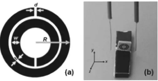
op-posite sides. Figure 1共a兲 shows a schematic drawing of a single SRR. The structural parameters, as provided in Fig.
1共a兲, are d = t = 0.2 mm, w = 0.9 mm, and R = 3.6 mm. Planar SRR array is fabricated on FR4 printed circuit boards, and unit cells of SRRs are extracted from the array. Surface mount capacitors with various capacitance values are placed at three different capacitive regions of SRRs. Namely,共i兲 the gap region between inner and outer rings, 共ii兲 outer ring’s split region, and 共iii兲 inner ring’s split region. The photo-graphs of the SRRs loaded with capacitors are given in the insets of Figs.2共a兲–2共c兲, respectively.
The resonance behavior could be observed from the fre-quency response of single SRR. Two monopole antennas are used to transmit and detect the EM waves through the single SRR unit cell. The monopole antenna was constructed by removing the shield around one end of a microwave coaxial cable. The exposed center conductor which also acted as the transmitter and receiver was on the order of/2, arranged to work at the frequency range covering the m of the SRR
structures. A single SRR is placed between the monopole antennas as shown in Fig. 1共b兲. The distance between the monopole and SRR unit cell is 6 mm. Monopole antennas are then connected to the HP-8510C network analyzer to measure the transmission coefficients. First, we measured the transmission spectra in free space 共i.e., without SRR unit cell兲, which is used as the calibration data for the network analyzer. Then, SRR unit cell was inserted between the monopole antennas, and we performed the transmission mea-surements by maintaining the distance between the transmit-ter and receiver monopole antennas fixed.
a兲Electronic mail: [email protected] FIG. 1.of experimental setup for measuring transmission coefficients.共a兲 Schematic picture of a single split ring resonator. 共b兲 Photograph
III. RESULTS
Split ring resonators consist of two concentric rings separated by a gap, both having splits oriented at opposite sides. Magnetic resonance is induced by the splits at the rings and the gap between the concentric rings. Current can-not flow around any one ring because of the splits, but the capacitance at the gap between the two rings enables current to flow.1 SRRs can be modeled as LC circuits where the inductance arises from the rings.9,10 Total capacitance of the SRR system has mainly two contributions. The first one is the capacitance at the split regions and the second contribu-tion is from the gap between the concentric rings. These capacitances together with the inductances from the rings determine the m of the resonator structure. Changing the
capacitance and inductance values results in a change inm
of SRRs, as expected from an LC circuit. Recently Aydin et al. studied the effects of several SRR parameters such as split width, gap distance, and metal width on magnetic reso-nance frequency of SRRs.6
Magnetic resonance frequency of SRR without any ad-ditional capacitance is measured at 3.82 GHz 共data not shown here兲.5
Firstly, we mounted capacitors at the gap re-gion between the inner and outer rings 关see Fig. 2共a兲兴. The capacitance at the gap region is therefore changed, which affects the total capacitance of the system. Measured trans-mission coefficients of SRRs loaded with different capaci-tances are provided in Fig. 3共a兲. The magnetic resonance frequency is reduced down to 3.44 GHz for SRR loaded with C = 0.2 pF and to 2.86 GHz for C = 3.3 pF.
We also performed simulations to check the experimen-tal results. Simulations are performed by using commercial software CST MICROWAVE STUDIO, which is a three-dimensional共3D兲 full-wave solver employing the finite inte-gration technique 共FIT兲.14 In order to determine the reso-nance frequencies of the structures under consideration, we have included one layer of the SRR structures along the propagation direction. In the simulation setup, the structures are subjected to an incident plane wave. Open boundary con-ditions are employed along the propagation direction. Peri-odic boundary conditions are used along the directions other than the propagation direction. Hence, the structure is as-sumed to be periodic and infinite along the directions that are perpendicular to the propagation direction. The transmission amplitudes are obtained by using the fields at a distant point from the structures. This point was chosen such that beyond this point the transmission coefficients do not change with increasing distance. Such a choice was made to exclude the near-field effects due to the highly resonant nature of the structures under consideration. The simulation software
en-ables us to insert lumped elements into the structure. We inserted capacitors and assigned capacitance values by using this tool. Figure3共b兲shows the simulated transmission spec-tra, and there is a good agreement between experimental re-sults and numerical simulations.
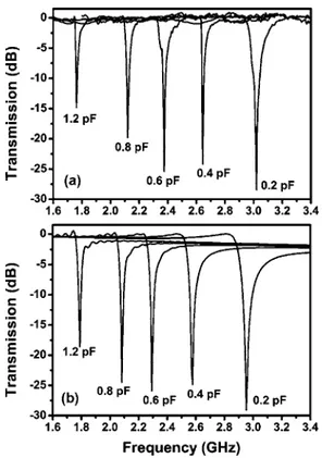
Secondly, we integrated capacitors at the split region of the outer ring关see Fig.2共b兲兴. Measured transmission coeffi-cients of SRRs with different capacitors are provided in Fig.
4共a兲. Resonance frequency significantly shifts to 2.87 GHz when C = 0.1 pF is mounted to the outer ring’s split region. Magnetic resonance frequency can further be reduced down to 0.99 GHz by using a C = 2.2 pF capacitor. The tuning range is higher for a capacitance loaded at the split region than a capacitance loaded at the gap region. Numerical re-sults that are provided in Fig.4共b兲agree quite well with the experimental data. A similar experiment was performed in an earlier study of our group.6We included experimental results with different capacitance values in this letter to make a comparison for the cases where the capacitances are loaded at the inner split and gap regions. We also decreased the magnetic resonance frequency furthermore in this study.
Finally, we loaded capacitances at the split region of the inner ring关see Fig.2共c兲兴. Figures5共a兲and5共b兲display mea-sured and calculated transmission coefficients for different capacitance values, respectively. For C = 0.2 pF and C = 1.2 pF the resonances are observed at 3.24 and 1.76 GHz, respectively.
The magnetic resonance frequencies of SRRs as a func-tion of capacitances loaded at different capacitive regions are shown in Fig. 6 with corresponding data points. It is clear from Fig. 6 that the highest amount of tuning can be achieved by loading capacitances at the outer split region. FIG. 2. 共Color online兲 SRR with capacitor loaded 共a兲 in the gap region
between concentric rings,共b兲 in the outer split region, and 共c兲 in the inner split region.
FIG. 3. Transmission coefficients of SRR structures with capacitors loaded at the gap region between inner and outer rings:共a兲 experimental data, and 共b兲 numerical simulations.
We also checked the experimental results with the numerical models in the literature. The capacitances due to the splits were ignored and only gap capacitance is taken into account when modeling SRR structure in Ref.9and10.
In general, the split capacitances are relatively small and can be ignored. However, if a capacitor is loaded in the split region, the split capacitance becomes important and affects resonance frequency as observed in our study. In Refs. 11
and 12, the capacitances due to the splits were taken into account; therefore we will use this model to compare our experimental results. The approximate formula for the lowest magnetic resonance frequency is given in Ref.12as
m=
冑
2Lav关共Cg/2兲 + Cs1+ Cs2兴, 共1兲where Lavis the average inductance of the two rings, Cg is
the capacitance due to the gap, and Cs1and Cs2are capaci-tances due to the outer and inner splits, respectively. By us-ing the formula provided in Ref. 10, we calculated the gap capacitance as Cg= 0.14 pF. The capacitances due to the
splits are calculated to be Cs1= Cs2= 1.2 fF. Since the mag-netic resonance frequency of our SRR structure is at m
= 3.82 GHz, by substituting the known parameters in共1兲the average inductance is found to be Lav= 76.7 nH. The capaci-tors inserted at the split region is connected in parallel to the split capacitance, therefore we can insert Cs1= C in 共1兲 and
plot the corresponding curve for the outer split. Note that C is the capacitance value of the surface mount capacitor. The results obtained from the model are plotted with a blue line in Fig. 6 and the results extremely agree well with experi-mental data. It is clear from the experiexperi-mental observations that the effect of the capacitance in the inner split region is
less than that of the outer split region. Therefore we can introduce a phenomenological factor in the model to obtain the best fit with the experimental data. In共1兲if we put 0.4Cs2
instead of Cs2, the red line in Fig.6 is obtained. As clearly
seen, the match between the model and the experimental results is quite good.
To obtain the results for the capacitor loaded at the gap region, we can use the model by Marques et al.9In the model the rings are divided into two parts as right and left halves. These two halves are connected in series. When we insert the capacitor at the gap region, we connect it in parallel to one half. It is clear that the amount of increase in the gap capaci-tance will not be as high as in the cases in the outer and inner splits since two halves are connected in series. By using the FIG. 5. Transmission coefficients of SRR structures with capacitors loaded at the inner split region: 共a兲 experimental data and 共b兲 numerical simulations.
FIG. 6.共Color online兲 Magnetic resonance frequency of a split ring resona-tor as a function of loaded capacitances at different capacitive regions. The solid lines are the results obtained from the numerical models.
FIG. 4. Transmission coefficients of SRR structures with capacitors loaded at the outer split region: 共a兲 experimental data and 共b兲 numerical simulations.
model proposed in, Ref.9, we plotted the green curve for the capacitors loaded at the gap region, which also agrees well with the experimental results. The model in Ref. 11 also gives the same result, since it is the special case of the model9with the split capacitances taken into account.
As a comparison,m shifted down to 2.86 GHz with a
3.3 pF capacitor loaded at the gap region. But the same amount of tuning has been achieved with a 0.1 pF capacitor at the split region of the outer ring. To reduce m down to
2.86 GHz, a capacitor with capacitance value between 0.2 and 0.4 pF is required to be loaded at the inner ring’s split region. Instead of mounting varactors at the gap region, put-ting them at the split regions should result in higher tunabil-ity ranges for SRR structures.13The highest tunability range is achieved with capacitors at the outer ring’s split region. Pendry et al. argued that the energy is concentrated at the very small volumes of the SRRs.1Therefore by loading ca-pacitors at small volumes of SRR, such as gaps or splits, one can achieve high EM response from the SRR structures de-pending on the position of the loading.
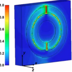
We have simulated the electric field intensity at the reso-nance frequency of SRR by usingCST MICROWAVE STUDIO.14 An electric field monitor is placed at the resonance frequency and the resulting intensity profile is plotted in Fig. 7. The intensities are normalized with respect to the maximum in-tensity value. It is clear that the electric field is mostly con-centrated at the outer ring’s split region. The E field is also localized at the inner split region and gap region, but local-ization is not as strong as the case in the outer split region. Therefore one should consider using a split region to achieve tunability or nonlinearity from SRR structures instead of the gap region. By loading capacitances, we not only change the magnetic resonance frequency but also change the effective permeability values of SRR. Lee et al. studied the effect of tunable components on the effective parameters of SRR structure.15
It is worth mentioning at this point that by loading the capacitor at the split region of the outer ring with a value of C = 2.2 pF, we managed to obtain m at 0.99 GHz. This is
the highest reduction of resonance frequency of a SRR. The
diameter of the SRR structure is 7.2 mm and the free-space wavelength at 0.99 GHz is 303 mm. Therefore magnetic resonance is achieved by using a subwavelength structure with a size of/42. It is worth mentioning at this point that it is possible to obtain magnetic resonances with lower fre-quencies by making use of other resonator systems. The size of a capacitively loaded loop is/500,16a wide capacitively loaded ring is /320,17 and a capacitively loaded double-sided spiral is /250,18 where corresponds to the wave-length at the magnetic resonance. Another prominent struc-ture is a Swiss roll with a relative diameter of /700.19
IV. CONCLUSION
We used several capacitors with varying values of ca-pacitances to load the capacitive regions of SRR. Experimen-tal and numerical results show that the position of the capaci-tor affectsmconsiderably. We also validated the results by
using the numerical models given in Refs. 9 and 11. The highest reduction of m is achieved when capacitors are
loaded at the outer ring’s split region. By using SRRs with subwavelength sizes共/42兲, it is possible to obtain magnetic resonance. We believe that our study will shed light on fur-ther numerical models of the SRR structures. Capacitor-loaded SRRs can be used as tunable metamaterial compo-nents, where one can change the magnetic resonance frequency, negative refractive index region, and effective pa-rameters of SRRs.
ACKNOWLEDGMENTS
This work is supported by the European Union under the projects DALHM, NOE-METAMORPHOSE, EU-NOE-PHOREMOST, and TUBITAK under Project Nos. 104E090, 105E066, and 105A005. One of the authors共E. O.兲 also acknowledges partial support from the Turkish Academy of Sciences. Another author 共K. A.兲 thanks M. D. Caliskan for his help in mounting the capacitors.
1J. B. Pendry, A. J. Holden, D. J. Robbins, and W. J. Stewart, IEEE Trans.
Microwave Theory Tech. 47, 2075共1999兲.
2D. R. Smith, W. J. Padilla, D. C. Vier, S. C. Nemat-Nasser, and S. Schultz,
Phys. Rev. Lett. 84, 4184共2000兲.
3K. Aydin, K. Guven, M. Kafesaki, L. Zhang, C. M. Soukoulis, and E.
Ozbay, Opt. Lett. 29, 2623共2004兲.
4K. Aydin, K. Guven, C. M. Soukoulis, and E. Ozbay, Appl. Phys. Lett. 86,
124102共2005兲.
5K. Aydin, K. Guven, N. Katsarakis, C. M. Soukoulis, and E. Ozbay, Opt.
Express 12, 5896共2004兲.
6K. Aydin, I. Bulu, K. Guven, M. Kafesaki, C. M. Soukoulis, and E. Ozbay,
New J. Phys. 7, 168共2005兲.
7T. Weiland, R. Schuhmann, R. B. Greegor, C. G. Parazzoli, A. M. Vetter,
D. R. Smith, D. C. Vier, and S. Schultz, J. Appl. Phys. 90, 5419共2001兲.
8P. Gay-Balmaz and O. J. F. Martin, J. Appl. Phys. 92, 2929共2002兲. 9R. Marques, F. Mesa, J. Martel, and F. Medina, IEEE Trans. Antennas
Propag. 51, 2572共2003兲.
10B. Sauviac, C. R. Simovski, and S. Tretyakov, Electromagnetics 24, 317
共2004兲.
11M. Shamonin, E. Shamonina, V. Kalinin, and L. Solymar, Microwave Opt.
Technol. Lett. 44, 133共2005兲.
12A. Radkovskaya, M. Shamonin, C. J. Stevensm, G. Faulkner, D. J.
Ed-wards, E. Shamonina, and L. Solymar, Microwave Opt. Technol. Lett. 46, 473共2005兲.
FIG. 7. 共Color online兲 Simulated electric field intensity profile at the mag-netic resonance frequency of the split ring resonator.
13I. Gil, J. Garcia-Garcia, J. Bonache, F. Martin, M. Sorolla, and R.
Marques, Electron. Lett. 40, 1347共2004兲.
14User Manual, Version 5.0, CST GmbH, Darmstadt, Germany, 2005,
http://www.cst. de
15S.-W. Lee, Y. Kuga, and A. Ishimaru, Electromagn. Waves 51, 219
共2005兲.
16M. C. K. Wiltshire, E. Shamonina, I. R. Young, and L. Solymar, Electron.
Lett. 39, 215共2003兲.
17O. Sydoruk et al., Phys. Rev. B 73, 224406共2006兲.
18R. R. A. Syms, I. R. Young, and L. Solymar, J. Phys. D 39, 3945共2006兲. 19M. C. K. Wiltshire, J. B. Pendry, I. R. Young, D. J. Larkman, D. J.