Machine Vision based Defect Detection Approach
using Image Processing
Mehmet BAYGIN
1, Mehmet KARAKOSE
2Computer Engineering Department 1Ardahan University, 75000
Ardahan, Turkey
[email protected], [email protected]
Alisan SARIMADEN
3, Erhan AKIN
2Computer Engineering Department 2Firat University, 23119
Elazig, Turkey
[email protected], [email protected] Abstract— Machine vision systems are used in industrial
production areas to produce products with fast, perfect and high precision. These systems allow users to make highly accurate and non-contact measurements and can detect deficiencies in the production process. In this work, a machine vision based non-contact defect detection algorithm for printed circuit boards (PCBs) has been developed. In this approach, which detects and controls the holes on the PCB, first a reference image is taken from the system and feature extraction process is applied to this image. In this real-time working approach, the reference image is matched with the incoming test images and the missing holes on the PCB are precisely detected. Furthermore, it has been determined that the error amount is less than 2 ȝM in experimental studies. This approach, which works independently of color, position and direction, enables the defect detection process to be done very quickly and precisely.
Index Terms—Machine vision, image processing, defect
detection, PCB, counting.
I. INTRODUCTION
Machine vision systems include observations made on industrial production lines, usually through a camera [1]. In this approach, without requiring any specialist control, processes such as the counting of products, the detection of defects or the measurement of their dimensions are carried out [2, 3]. With these systems, very fast, smooth and perfect measurements can be made. In this way, the production capacity is increased and complete products can be delivered to the end user. Depending on the developing technology, camera and machine vision systems are continuously improving [4]. Thanks to the development of equipment capable of measuring at very high speeds, these systems have become available in almost all production facilities. In addition, machine vision systems are often preferred on production lines in order to provide complete contactless control without requiring any specialist supervision and consequently reduce costs in the area of quality control [5, 6].
In industrial areas, measurement of production facilities is usually done in two ways, contact and contactless [7]. In the contact measurement approach, the operations are done entirely visually and the amount of error is quite large. The performance of this method is very low, especially in areas requiring precise measurement. In the non-contact
measurement approach, these operations are accomplished through one or more cameras and a machine vision software. The different features of the products can be easily detected in this approach which provides fast solutions according to the performance of the computer system used [8, 9]. In one of the studies performed on the subject, the final stage of the production of electric chips was controlled by the tape and reel packaging process. An approach that can control 200 chips per minute using multiple threads and parallel programming techniques has been developed in the study. Experimental studies have shown that the proposed approach can complete operations with high accuracy and speed. [10]. Wang et al. [11], have developed a machine vision based automated inspection approach. This approach, which controls the holes on the PCBs, determines the properties such as the number of holes and the defect. According to the results obtained in the study, the proposed approach can work with a 5um error rate. In this approach, a CCD camera, 3-axis positioning system, light source and computer are used. A block diagram of the experimental setup implemented and used in this paper is shown in Fig. 1. In a study performed by Karakose et al. [12], a process of counting products in an industrial production line running at high speed was performed. The proposed approach is basically a background extraction process and the boundaries of the products passing through the conveyor have been determined. The process of counting over-the-top products has also been carried out. In experimental studies, it has been observed that the proposed approach gives fast and accurate results.
PC
Fig. 1. An example study of literature [11]
In another study on the subject, a vision-based robotic approach was developed to collect and control small pieces of automotive components. The study is divided into parts as part identification, machine learning based classification, analysis of circular objects, and segmentation of objects. The approach suggested in the study was tested in real time and the results verified [13]. Yang et al. [14] studied the defects occurring on the conveyor. Conveyor images obtained through a linear CCD camera were transmitted to the main machine and defects on the conveyor were detected by image processing. In another study, the classification of coins was carried out. The coins passing through a moving conveyor have been detected and counted. The accuracy and performance of the proposed approach are achieved using particle classification, pattern matching and geometric matching methods. In the study, a rate of 1000 coins per minute was reached and an accuracy of about 95% was achieved [15]. Machine vision applications are frequently used in many different areas. In one of the studies conducted at this point, Yaman et al. [16] developed a particle-based optimization approach for railways. In the study, the railway is taken with four different cameras and various image processing algorithms are applied to these images. As a result, railway components and surface defects are detected. In another work carried out, automatic object counting has been introduced. In this proposed approach, the steps of image acquisition, preprocessing, segmentation and counting are basically used. As a result of experimental studies, it is determined that the proposed approach works with high success rate and a block diagram summarizing this study is given in Fig. 2. [17].
In this study, a machine vision based quality control application for PCBs was developed. With the proposed approach, the holes on the PCBs are detected, counted and the deficiencies are determined. In the study, images of PCBs are taken through a camera and examined with specific image processing algorithms. Basically, this approach, which uses the Otsu and Hough transformations, performs detection and inspections independently of position, direction and color conditions. For this purpose, the steps and details of the proposed approach are presented in the second section of the study. In the third section of the study, the results obtained from experimental studies are given. In the last section, the results are examined.
Input Image RGB to HSV Split HSV Image S Channel V Channel Threshold Combine Morphological Operation Calculate Size of Components Counting Fig. 2. An example flowchart of literature [17]
II. PROPOSED APPROACH
At the beginning of the fields where machine vision applications are used, there is a defect detection. It is aimed to determine the deficiencies of the products passing through a conveyor and deliver perfect and complete products to the end user. In this process, which usually covers the final stages of machine vision applications, defective products are detected and separated from the conveyor. In this work, object detection, counting and defect detection processes are mainly developed for machine vision applications. The proposed approach works in real time and identifies holes in the PCB to determine if there are any defects on these products. A sample image for the PCBs used in the study is presented in Fig. 3.
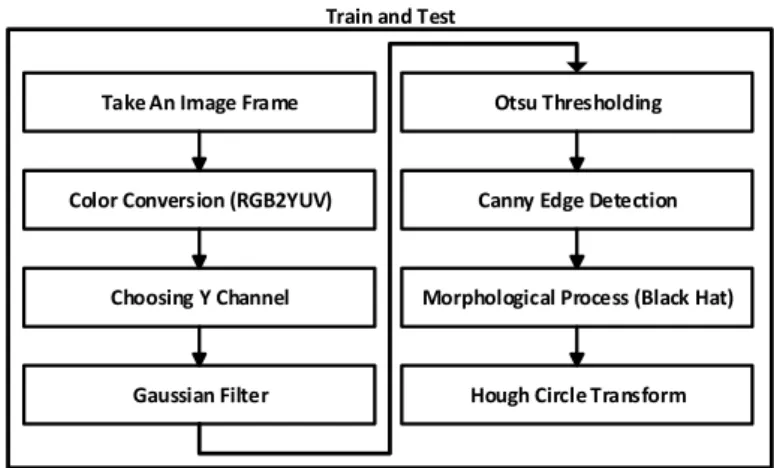
The proposed approach basically uses feature extraction and feature matching operations. Otsu thresholding and Hough transformation methods are used in the feature extraction process. For a reference image, the results obtained from this process are saved for later use. At this point, the number of holes, position and center information on the PCB are obtained. The same process is applied to the test images that follow this process and finally the defects on the PCB are detected together with the feature matching process. A block diagram summarizing the steps of the proposed approach is given in Fig. 4.
Fig. 3. Sample image for PCB
Take An Image Frame
Color Conversion (RGB2YUV)
Choosing Y Channel
Gaussian Filter
Otsu Thresholding
Canny Edge Detection
Morphological Process (Black Hat)
Hough Circle Transform Train and Test
In the proposed approach, the image of the PCB is taken firstly through a camera. This image is transmitted to the main machine and the image processing algorithm is executed. In the first step of the algorithm, the RGB image is converted into the YUV color space by converting the color space. Following this conversion, the processes from which the image is obtained are performed on this channel. The conversion from RGB color space to YUV color space is given in Equation 1.
xB
xG
xR
Y
=
0
.
299
+
0
.
587
+
0
.
114
xB
xG
xR
U
=
−
0
.
147
−
0
.
289
+
0
.
436
(1)xB
xG
xR
V
=
0
.
615
−
0
.
515
−
0
.
100
In the next step of the proposed approach, the noise in the image is eliminated by using the Gauss filter. The mathematical expression that performs this operation is presented in Equation 2.
(
)
( )
2 2 2 2 2 2 1 ) ( σπσ
r N e r G = − (2) In the next step of the algorithm, the image is converted to a binary image by using Otsu threshold method. In this method, the optimal threshold value of the image is adaptively determined. The reason for using the thresholding method is to be able to clearly show all the details in the image. The Canny edge extraction method is applied to the image obtained using the Otsu method. At this point, all the edges in the image are precisely defined [18]. After this process, a morphological process is applied to the image. This process thickens the edges of the resulting image. This process, referred to as Black Hat in the literature and it is presented in Equation 3.In the last step of the proposed approach, Hough transformation is applied to the image. The holes in image are precisely identified and marked with Hough transformation. In addition, the number of holes, positions and diameters in the image are determined by this transformation. This information is used for feature matching in test images. In this point, missing holes in each new image can be detected and defective products can be identified. A pseudo code for Hough transform used in the study is presented in Fig. 5 [19, 20].
For each pixel (x,y)
For each radius r=10 to r=60
For each theta t=0 to 360
a=x – r * cos(t * PI/180);
a=x – r * cos(t * PI/180);
A[a, b, r] + = 1;
end
end
end
Fig. 5. A pseudo code for Hough circle transform
src
element
src
close
element
src
blackhat
dst
=
(
,
)
=
(
,
)
−
(3)))
,
(
(
)
,
(
src
element
dilate
erode
src
element
close
=
The proposed approach is basically composed of 8 steps. However, after this process, the feature matching method is used for the test phase. In this way, not only the number of holes on the PCB, but also their position can be controlled. Accordingly, defective products are separated in the system.
III. EXPERIMENTAL RESULTS
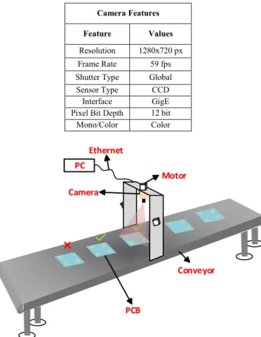
The results obtained in the study were obtained from an experimental setup capable of real-time operation and measurement. One camera is integrated in the system which has a motorized structure and which can move with three axes. The camera constantly monitors the surface and collects the image. With this camera, which can take up to 60 frames at a time, the image of the PCBs is instantly transmitted to the main machine. The connection between the camera and the main machine is provided via Ethernet. Details of this camera are presented in Table 1. On the main machine, the machine vision application which can detect and measure for PCBs is running. The proposed approach is implemented using OpenCV and a block diagram summarizing the experimental setup used in the study is given in Fig. 6.
TABLEI.CAMERA FEATURES USED STUDY
Camera Features
Feature Values Resolution 1280x720 px Frame Rate 59 fps Shutter Type Global Sensor Type CCD
Interface GigE Pixel Bit Depth 12 bit
Mono/Color Color Ethernet Motor PC Camera Conveyor PCB
In the proposed approach, the test procedures were performed for different conditions. This algorithm, which can work independently of direction and position, can perfectly detect the holes on the PCB. Example image processing results of the training data is given in Fig. 7.
a) Source Image b) Gauss Filter c) Y Channel
d) Otsu Threshold e) Canny Edge Detection f) Black Hat
g) Hough Transform Fig. 7. Training process for PCB board
As can be seen from Fig. 7, the proposed approach consists essentially of 8 steps. First, the process starting with image capture ends with the detection of the holes on the PCB. The number of holes detected, coordinates and center information are recorded for use in test operations. The results given in Fig. 7 show the results of the training process.
In the testing process of the machine vision application for PCBs, the feature matching process is applied. The steps given in Fig. 7 are applied to the test images. The features obtained after this process are compared with those obtained from the training data and the defects of the products are determined. A sample test results for this step of the proposed approach are presented in Fig. 8.
a) Source Image b) Gauss Filter c) Y Channel
d) Otsu Threshold e) Canny Edge Detection f) Black Hat
g) Hough Transform Fig. 8. Test process for PCB board
The test procedures performed for the proposed approach as mentioned at the beginning section is applied to different conditions. In particular, test operations were carried out for images from different locations and successful results were obtained. The sample results of these tests are presented in Fig. 9.
a) Fail Sample b) True Sample Fig. 9. An example results of test process
IV. CONCLUSIONS
Today machine vision applications are frequently used in many industrial production lines. These applications, which are used for various purposes such as object counting, defect detection and measurement, increase the capacity of production lines and produce products that are close to zero defects.
In this paper, a defect detection method based on machine vision has been developed. With this proposed approach, the number and position of the holes on the PCBs were determined, and the number and positions of the missing holes were detected. Images taken via a real-time camera were analyzed with the image processing algorithm designed within the scope of the study and feature extraction was performed. After performing the same operations on the test images, feature matching method was used and defects on the products were detected. In the proposed approach, the images were taken with a camera integrated in a system capable of operating in three axes. Basically, Otsu thresholding and Hough transformations have been used and a system with adaptive structure has been established. The experimental results obtained in real-time have shown that the proposed method provides very fast and effective results.
ACKNOWLEDGMENT
This study has been supported by The Scientific and Technological Research Council of Turkey (SANTEZ Programme) under Research Project No: 0743.STZ.2014 (TUBITAK Grant No:112D021).
REFERENCES
[1] S. Nashat, A. Abdullah, and M. Z. Abdullah, “Machine vision for crack inspection of biscuits featuring pyramid detection scheme,” Journal of Food Engineering, vol. 120, pp. 233-247, 2014.
[2] J. Molleda, R. Usamentiaga, D. F. Garcia, F. G. Bulnes, and L. Ema, “Shape measurement of steel strips using a laser-based three-dimensional reconstruction technique,” IEEE Transactions on Industry Applications, vol. 47, no. 4, pp. 1536-1544, 2011. [3] P. S. Khude, and S. S. Pawar, “Object detection, tracking and
counting using enhanced BMA on static background videos,” IEEE International Conference on Computational Intelligence and Computing Research (ICCIC), Tamilnadu, India, 2013. [4] M. Baygin, and M. Karakose, “A new image stitching approach
for resolution enhancement in camera arrays,” 9th International Conference on Electrical and Electronics Engineering (ELECO), pp. 1186-1190, 2015, Bursa, Turkey.
[5] P. Thammasorn, S. Boonchu, and A. Kawewong, “Real-time method for counting unseen stacked objects in mobile,” 20th IEEE International Conference on Image Processing (ICIP), pp. 4103-4107, 2013, Melbourne, Australia.
[6] B. Zhang, W. Huang, J. Li, C. Zhao, S. Fan, J. Wu, and C. Liu, “Principles, developments and applications of computer vision for external quality inspection of fruits and vegetables: A review,” Food Research International, vol. 62, pp. 326-343, 2014.
[7] M. S. Raman, and M. Sukanya, “A novel labelling algorithm for object counting,” Third International Conference on Computing
Communication & Networking Technologies (ICCCNT), 2012, Coimbatore, India.
[8] O. Yaman, M. Baygin, and M. Karakose, “A New Approach Based on Image Processing for Detection of Wear of Guide-Rail Surface in Elevator Systems,” International Journal of Applied Mathematics, Electronics and Computers, vol. 4, pp. 296-300, 2016.
[9] E. S. Gadelmawla, “Computer vision algorithms for measurement and inspection of spur gears,” Measurement, vol. 44, no. 9, pp. 1669-1678, 2011.
[10] J. Y. Lee, C. H. Han, K. W. Ko, and S. Lee, “Development of vision system for defect inspection of electric parts in the tape and reel package,” 16th IEEE International Conference on Control, Automation and Systems (ICCAS), pp. 437-439, Gyeongju, South Korea, 2016.
[11] W. C. Wang, L. B. Chen, W. J. Chang, S. L. Chen, and K. S. M. Li, “A Machine Vision Based Automatic Optical Inspection System for Measuring Drilling Quality of Printed Circuit Boards,” IEEE Access, 2016.
[12] M. Karakose, M. Baygin, I. Aydin, A. Sarimaden, and E. Akin, “Endüstriyel Sistemlerde Arkaplan ÇÕkarÕmÕ TabanlÕ Hareketli Nesne Tespiti ve SayÕlmasÕ için Yeni Bir YaklaúÕm,” Mus Alparslan Universitesi Fen Bilimleri Dergisi, vol. 4, no. 2, pp. 373-381, 2016.
[13] O. Semeniuta, S. Dransfeld, and P. Falkman, “Vision-based robotic system for picking and inspection of small automotive components,” IEEE International Conference on Automation Science and Engineering (CASE), pp. 549-554, Fort Worth, TX, USA, 2016.
[14] Y. Yang, C. Miao, X. Li, and X. Mei, “On-line conveyor belts inspection based on machine vision,” Optik-International Journal for Light and Electron Optics, vol. 125, no. 19, pp. 5803-5807, 2014.
[15] K. D. Joshi, B. W. Surgenor, and V. D. Chauhan, “Analysis of methods for the recognition of Indian coins: A challenging application of machine vision to automated inspection,” 23rd IEEE International Conference on In Mechatronics and Machine Vision in Practice (M2VIP), pp. 1-6, Nanjing, China, 2016. [16] O. Yaman, M. Karakose, and E. Akin, “PSO Based Diagnosis
Approach for Surface and Components Faults in Railways,” International Journal of Computer Science and Software Engineering (IJCSSE), vol. 5, no. 5, pp. 89-96, 2016.
[17] A. A. Khule, M. S. Nagmode, and R. D. Komati, “Automated object counting for visual inspection applications,” International Conference on Information Processing (ICIP), pp. 801-806, Quebec City, Canada, 2015.
[18] G. T. Shrivakshan, and C. Chandrasekar, “A comparison of various edge detection techniques used in image processing,” IJCSI International Journal of Computer Science Issues, 2012, vol. 9, no. 5, pp. 272-276.
[19] O. Yaman, M. Karakose, I. Aydin, and E. Akin, “Detection of pantograph geometric model based on fuzzy logic and image processing,” 22nd Signal Processing and Communications Applications Conference (SIU), pp. 686-689, Trabzon, Turkey, 2014.
[20] Y. J. Cha, K. You, and W. Choi, “Vision-based detection of loosened bolts using the Hough transform and support vector machines,” Automation in Construction, vol. 71, pp. 181-188, 2016.
![Fig. 1. An example study of literature [11]](https://thumb-eu.123doks.com/thumbv2/9libnet/3909693.45009/1.892.489.801.868.1049/fig-an-example-study-of-literature.webp)