Torque Ripple Minimization of
a
Switched
Reluctance
Motor
Bilgig
M. 0
. ,
Ozbulur
V.
,
Tiibitak, Marmara Research Center CAD/CAM Robotics Department
Gebze, Kocaeli, Turkey 41470
Sabanovic A .
ABSTRACT
-
This paper presents a sintple technique to minimize torque ripple of a Switched Reluctance Motor. The technique is based on the control of the sum of the square of the phase currents by using only two current sensors and analog multipliers. The simulation results and a proposed circuit are given. The advantages and its limitations of the proposed circua are explained.1. INTRODUCTION
Switched Reluctance Motor
(SRM)
becomes an attractive alternative in adjustable speed drive due to its simplicity in both motor constructions and power converter. Excessive torque ripple, especially at low speeds is still one of the important reasons for Switched Reluctance Motor not to be acceptable in variable speed drive market. This torque ripple comes from motor’s stepping nature and has undesirable effects to the bearing system and produces acoustic noise. It does not allow to use SR motor in servo applications.Several efforts to reduce or eliminate the torque ripple of Switched Reluctance Motor are presented in literature. In [1,2 ] phase current shape is modulated to counteract the torque ripple. This technique requires a special motor geometry and pole shape design. A balanced commutator which works for accurate current tracking to reduce torque pulsations is reported in [ 3 1. This technique needs computations and is based on measured motor data. The method described in [ 4 ] optimizes the conmutation angle for torque ripple reduction. This work needs excessive memory to use recalculated optimal position
-
phase current values which are obtained from the nonlinear T=T ( 8, i ) torque curves. Torque ripple minimization method given in [ 53
is based on the estimation of the instantaneous Switched Reluctance Motor torque from the flux linkage versus current and rotor position charecteristic curve via bi-cubic spline interpolation. The estimation is achieved by a simulation model using a DSP.The application of a variable structure system theory to the speed control of Switched Reluctance Motor given in [ 6 ]
results that this control is also effective in reducing the torque ripple of the motor, compensating for the nonlinear torque charecteristics. Only simulation results are given in that paper. Its practical implementation needs accurate dynamic speed measurements. Some small torque ripple exibited in simulation are explained by temporary outgoing of the drive from sliding regime.
In this paper a simple technique is proposed to modulate phase currents to eliminate torque ripple by using only two current sensors. Simulation results are given, the advantages and limitations of the technique are explained.
The paper is organized as follows. In section two the mathematical model is given. Section three and four give simulation results with conventional and proposed methods. Experimental results are given in section five. Finally, section six concludes the work.
2. THE MATHEMATICAL MODEL
The Switched Reluctance Motor used in the simulation is a 816 SRM with C
-
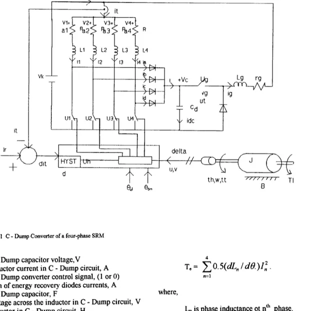
Dump converter. Figure 1 shows the motor, the converter and the control.The state equations of this system are
dL,,/dt = V , , - R . 1 , ( n = 1 , 2 , 3 , 4 ) dV, / dt = (-Ig
.
U, + I ) / C d dI,/dt = ( V g - $ . I , ) / L g dw /dt = ( T,-
TL-
B . w ) /J
de / d t = w flux of n* phase, Wb phase voltage of n* phase, V per phase coil resistance, Clphase current of n* phase, A
where, L,, t time, s V,, R I,]
ik
I
\I ,', it
I I
Fig. 1 C
-
Dump Converter of a four-phase SRMC - Dump capacitor voltage,V
inductor current in C
-
Dump circuit, A C-
Dump converter control signal, (1 or 0 )s u m of energy recovery diodes currents, A C
-
Dump capacitor, Fvoltage across the inductor in C
-
Dump circuit, V inductor in C-
Dump circuit, Hresistance of
Lg,
!2 angularspeed,
rad/s rotor position (angle), rad electrical torque,Nm
load torque, Nmcoefficient of viscous friction, Nm shad moment of inertia, kg m2
4
T,=
~ 0 . 5 ( d L n l d 6 . ) I ~
n=l
where,
L,,
is phase inductance ot n* phase.Following assumptions are made in the above model.
a ) The mutual inductances between phases are
zero.
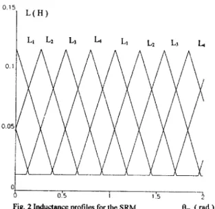
b ) The motor works in the linear region of its magnetic characteristics. The inductance profiles of phases are given in figure 2. The currents I,, can be calculated from fluxes by,
( 3 )
Electrical torque is,
0'15] L ( H )
-0.2
0
0.'5 1 I .5 -3
Fig. 2 Inductance profiles for the SRM
em
(rad 1V, and V, in equation ( 1 ) are defined according to the control strategy.
Om (rad) 3. SIMULATION
0.2
The simulation is achieved with Simnon Version 3.10 by using the mathematical model given in the equations
( 1 ). Simnon is a simulation program for non-linear systems
[ 7 1 . Runga
-
Kutta method is chosen to solve the state equations.d L i d0 (Hirad) /
In practice, voltage source is used to drive the motor and current is controlled. This can be done by controlling the total current as
i,
+
i2+
i3+
i4 = I,f ( 4 )with only one current transducer.
The torque variation, corresponding currents, inductances and their slopes which were obtained trough simulation are given in Figure 3 and 4.
The torque dip in figure 3.a can be explained by equation
( 2 )
.
The tail of phase current isnot
controlled. During commutation the rising edge of phase current is modulated to satisfy ( 3 ). However, this does not make the torque constant.Some data for the above simulation results are as follows Reference current..
...
.: Irrf = 3.4 ASpeed
...
: o = 30 radlsLoad
torque. ... : TL = 1.2 N.niSource voltage ... : V, = 300 V C-Dump voltage.
...
: Vc = 600 V 1.5 1 0.5 0.025 0.03 0.035 0 O AFig. 3 Simulation results
a) Torque variation
b) Phase currents L, 11 and 12 variation
dL1 I d 0 (Hkad) 0:4 0.'6 0l8 i -0.4
I
I I I 0, (rad )'
014 016Fig.4. Phase inductance LI ,L and their slopes dL1 /dB , dL, id0
Phase voltage on time.. .... .:
e,,,
= 0' Phase voltage width.. ... .: QC = 15'4. THE PROPOSED METHOD
Note
that the commutation from I4 to 1, occurs inpositive torque production period of both
L4
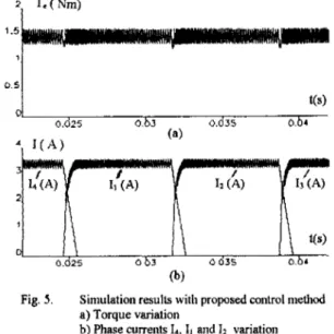
and L1 in figure3 and 4. Therefore the following control is more logical according to the equation ( 2 ) where the torque is proportional with the square of the currents.The proposed method based on the equation ( 5 ). This control is simulated with the same data used in the above section and the results are shown in Figure 5 . It is seen that the torque dip is appreciably eliminated. The ripple shown in the figure comes from the hysteresis current control and can be made as small as possible by reducing hysteresis band and increasing switching frequency.
0 . 5
1
1
* ' , ' b t ( s ) 0. 25 0 3 0.035 0. 4 (a) d I \ I \ 0.d25 0 b3 0 635 o.br (b)Fig. 5 . Simulation results with proposed control method a) Torque variation
b) Phase currents 14, 11 and 11 variation
5. EXPERIMENTAL RESULTS
We assume that only two phases can conduct current simultaneously. Therefore
Then,
Equation 7 shows that the proposed control can be done by using only two current sensors. A circuit to implement this control is given in Figure 6. The freewheeling diodes and C- dump converter is not shown in that circuit for simplification. The multiplier circuits shown in the figure are not necessarily high accuracy one. In
our
circuit Analog Devices AD633 multipliersare
used for squaring.(il +i312 Mult. Mult I2+14 L,
e
From positionFig.6. Proposed control circuit
Figure 7a and 7b shows the phase current waveforms taken from the oscilloscope without and with the proposed control
is
operated under the same conditions we used in simulation. Since we have no dynamic torque measurement system at this moment. The torque reductionis
justified in
two
ways.a
) The experimental and simulated current b ) Audible noise was reduced.waveforms were in close agreement
Fig. 7a Experimental phase current without the proposed control method
Proceeding of Intemational Confkrence on Electrical Machines, R. S. WALLACE,. D. G. TAYLOR,. " A Balanced Commutator for
Switched Reluctance Motors to Reduce Toque Ripple" IEEE Transactions on Power Eledronics. Vo1.7, No.4 p.617- 626,
October 1992.
SCHRAM D.S., WILLIAMS B.W., GREEN T.C., " Torque Ripple
Reduction of Switched Reluctance Motor by Phase Current Optimal Pmfiling " , EEE Power Electronics Specialists Conference Recod,
MOREIRA, J.C., cI Toque Ripple Minimization in Switched
Reluctance MdoR Via Bi-cubic Spline Interpolation "JEEE Power
Electronics Specialists
BUJAG.S., MENIS R., VALLA M.I., " Variable Structure Control
of a SRh4 Drive " , IEEE Transactions on Industrial Electronics,
Vol. 40, No:l, s. 56-63, February 1993
Simnon User's Guide for MS-DOS Computers, Version 3.10, March 1990.
ICEM'94 p.559-564, &IP 1994.
S. 857- 860,1992
Fig. 7b Experimental phase current with the proposed control method
Vertical 0.7 Ndiv Horizontal Zms/div
6. CONCL USIONS
A simple technique is given to minimize torque ripple
of
Switched Reluctance Motor. The proposed technique has the following advantages:1 ) Only two current sensors are required to apply 2 ) Accurate angle estimation or measurement is not 3 ) It is simple. No look-up table or digital
4 ) No modification on motor or pole geometry is the method,
needed,
calculation is necessary, required.
But, there are some limitations for the proposed method to apply. These are:
1 ) Inductance versus angle variation is assumed 2 ) In any time only one or two phases have to linear in the positive torque production period ,
conduct current.
However these limitations are easy to achieve especially at low speed. Therefore the technique given is very simple and helps to reduce torque ripple.
REFERENCES
[ 1 ] EGAN, M.G. et. aL. " A High Perfonllance
Drive : Achieving Servomotor Con. 1985
J. LECHENADEC., M. GEOFFROY., B. MULTON., J.
MOUCHOUX., '' Torque Ripple hlininiisation in Switched Relctance Motors by Optimisatioii of Current Wave-Fonns and of
Tooth Shape with Copper Losses and "V.A Silicon" Constraints. Variable Reluctance Control *' Proceedings of hlotor