OPTIMIZING AND INVESTIGATION IN TIG
WELDING PARAMETRIC INFLUENCE ON
TENSILE STRENGTH OF DISSIMILAR METALS
SS-304 AND LOW CARBON STEEL
2020
M. Sc. Thesis
Mechanical Engineering
Abduladim Abdulmagid BOGHDADI
OPTIMIZING AND INVESTIGATION IN TIG WELDING PARAMETRIC INFLUENCE ON TENSILE STRENGTH OF DISSIMILAR METALS SS-304
AND LOW CARBON STEEL
Abduladim Abdulmagid BOGHDADI
T.C.
Karabuk University Institute of Graduate Programs Department of Mechanical Engineering
Prepared as M. Sc. Thesis
Assoc. Prof. Dr. İsmail ESEN
KARABUK June 2020
“I declare that all the information within this thesis has been gathered and presented in accordance with academic regulations and ethical principles and I have according to the requirements of these regulations and principles cited all those which do not originate in this work as well.”
ABSTRACT
M. Sc. Thesis
OPTIMIZING AND INVESTIGATION IN TIG WELDING PARAMETRIC INFLUENCE ON TENSILE STRENGTH OF DISSIMILAR METALS SS-314
AND LOW CARBON STEEL
Abduladim Abdulmagid BOGHDADI
Karabük University Institute of Graduate Programs Department of Mechanical Engineering
Thesis Advisor: Assoc.Prof.Dr. İsmail ESEN
June 2020, 51 pages
This study aims to optimizing and investigation in TIG welding parametric influence on tensile strength of dissimilar metals SS-304 and low carbon steel. The literature survey and experimental work has been done. The welding process has been designed using Minitab software. The best tensile test results recorded by sample No. 3, which welded by (8 lt/min gas flow rate and 120 A current). The best hardness results recorded by sample No. 9 by 116 in weld metal and HAZ with (12 Gas flow rate and 120 welding current ampere).
The mean, Signal to Noise Ratios (S/N), and ANOVA Test have been utilizing to find out the highly effective welding parameter (current and gas flow rate).
Key Word : Tungsten Inert Gas Welding (TIG), S/N, ANOVA, Gas flow rate,
welding current, Dissimilar Metals.
ÖZET Yüksek Lisans Tezi
DÜŞÜK KARBONLU ÇELİK VE SS-314 BENZEMEZ METALLERİN TİG KAYNAĞI PARAMETRELERİNİN ÇEKME DAYANIMINA ETKİSİNİN
ARAŞTIRILMASI VE OPTİMİZASYONU
Abduladim Abdulmagid BOGHDADI
Karabük Üniversitesi Lisansüstü Eğitim Enstitüsü Makina Mühendisliği Anabilim Dalı
Tez Danışmanı: Doç.Dr. İsmail ESEN Haziran 2020, 51 Sayfa
Bu çalışma, düşük karbonlu çelik ve SS-314 benzemez metallerin TİG kaynağı parametrelerinin çekme dayanımına etkisinin araştırılması ve optimizasyonunu amaçlamaktadır. Çalışmada literatür taramasının ardından deneysel çalışmalar gerçekleştirilmiştir. Deneylerde kullanılacak kaynak işlem parametreleri Minitab yazılımı kullanılarak tasarlanmıştır. En iyi çekme test sonucu 8 lt/dk. gaz akış oranı ve 120 A akım ile elde edilmiştir. En iyi sertlik sonucu ise kaynak metalinde ve İTAB’da 12 lt/dk. gaz akış oranı ve 120 A akımı kullanılarak 9. deneyde 116 A sertlik değeri elde edilmiştir.
Etkili TİG kaynağı parametrelerinin tespiti için (akım ve gaz akış oranı) Sinyal Gürültü Oranları ve ANOVA testi kullanılmıştır.
Anahtar Sözcükler : Tungsten İnert Gaz Kaynak (TİG Kaynağı), S/N, ANOVA, Gaz Akış Oranı, Kaynak Akımı, Benzemez Metaller.
ACKNOWLEDGMENTS
Alhamdulillah, first I would like to thanks Allah Almighty, as finally I am able to finish my thesis.
First, I would thank my supervisor, my professors and teachers who have enlightened with all the knowledge that I possess and who have given me the confidence to strive to make myself better in every way on a daily basis.
I would also thank my parents, family, and friends whose blessings and support was the key to help me extend my reach and achieve new heights.
CONTENTS Page APPROVAL ... ii ABSTRACT ... iv ÖZET ... vi ACKNOWLEDGMENTS ... viii CONTENTS ... ix
LIST OF FIGURES ... xii
LIST OF TABLES ... xiii
SYMBOLS AND ABBREVIATIONS INDEX... xiv
PART 1 ... 1 INTRODUCTION ... 1 1.1 BACKGROUND ... 1 1.2 OBJECTIVES: ... 3 1.3 RESEARCH IMPORTANCE ... 4 1.4 EXPECTED CONTRIBUTION ... 4 1.5 METHODOLOGY ... 5 1.6 SCOPE OF WORK ... 6 PART 2 ... 8 LITERATURE REVIEW... 8 2.1 WELDING ... 8
2.1.1 Classification of Welding Types ... 8
2.1.2. Some Welding Methods ... 11
2.1.2.2 Frictional Welding ... 11
2.1.2.3 Cold Welding ... 12
Page
2.1.2.7 Ultrasonic Welding ... 14
2.1.2.8 Thermite Welding ... 15
2.1.2.9 Gas-Smelting Welding (Gas Welding) ... 15
2.1.2.10 ARC Welding ... 16
2.1.2.11 Electron Beam Welding ... 16
2.1.2.12 Laser Welding ... 17
2.1.2.13 Atomic Hydrogen Welding ... 18
2.1.2.14 Underwater Welding ... 18 2.2 TIG WELDING... 18 2.2.1 Process Discretion ... 18 2.2.2 Equipment ... 19 2.2.2.1 Power ... 19 2.2.2.2 Welding Gun ... 21 2.2.2.3 Control Equipment ... 21 PART 3 ... 23 EXPERIMENTAL ... 23 3.1 MATERIAL SELECTION ... 23 3.1.1 Stainless Steel ... 23 3.1.1.1 SS 304 ... 23 3.1.1.2 Chemicals Composition of SS 304 ... 25 3.1.1.3 Application of SS 304 ... 25 3.1.1.4 Mechanical Properties of SS 304 ... 26 3.1.2 Carbon Steel ... 26
3.1.2.1 Low Carbon Steel ... 26
3.1.2.2 Chemical Composition of Low Carbon Steel ... 27
3.1.2.4 Mechanical Properties of Low Carbon Steel ... 27
3.2 EQUIPMENT AND TOOLS ... 28
3.2.1 TIG Welding Machine ... 28
3.2.3 Testing Equipment ... 29
Page
3.2.3.2 Tensile Test Machine ... 30
PART 4 ... 33
RESULTS AND DISCUSSION ... 33
4.1 OVERVIEW... 33
4.2 WELDING PROCESS ... 33
4.2.1 The Preparation of Samples ... 33
4.2.1.1 Samples Geometry ... 33
4.2.2 Welding ... 34
4.2.2.1 Welding Process Design ... 34
4.3 TESTING ... 39 4.3.1 Tensile Test ... 39 4.3.1.1 Taguchi Analysis ... 40 4.3.2 Hardness Test ... 44 4.3.2.1 Taguchi Analysis ... 45 PART 5 ... 49 CONCLUSIONS ... 49 5.1 CONCLUSIONS ... 49 5.2 FUTURE RECOMMENDATIONS ... 50 REFERENCES ... 51
LIST OF FIGURES
Page
Figure 1.1. The weld bead metal of TIG welding process [9]. ... 2
Figure 1.2. The research methodology. ... 6
Figure 2.1. The most common welding methods [14]. ... 10
Figure 2.2. The motor driving of friction welding [14]. ... 12
Figure 2.3. Resistance butt welding [14]. ... 13
Figure 2.4. Applying plating to a billet by explosion welding [14]. ... 14
Figure 2.5. Mold set for thermite welding [14]. ... 15
Figure 2.8. Penetration of a laser beam welding [14]. ... 17
Figure 2.9. Gas tungsten ARC welding equipment [14]. ... 18
Figure 2.10. The TIG welding balance control and square wave [14]. ... 20
Figure 2.11. The pulse TIG requires principle that the weld pool be solidify in between pulses [14]. ... 20
Figure 2.12. TIG welding gun example [14]... 21
Figure 2.13. The Welding sequence example [14]. ... 22
Figure 3.1. Alpha-TIG200X TIG welding machine. ... 28
Figure 3.4. Servo-hydraulic load frames – HB series, 2-column tensile test machine ... 31
Figure 4.1. Welding specimen’s geometry. ... 33
Figure 4.2. First step opening Minitab. ... 34
Figure 4.3. Select Stat/DOE/Factorial/Create Factorial Design. ... 35
Figure 4.4. Second step Taguchi design. ... 36
Figure 4.5. Fourth step, setting up the Taguchi design factors. ... 37
Figure 4.6. Welding parameters design... 38
Figure 4.7. The main effects of means. ... 42
Figure 4.8. The main effects of SN ratios. ... 43
Figure 4.9. The main effects of means. ... 46
LIST OF TABLES
Page
Table 3.1. The chemical composition of SS-304. ... 25
Table 3.2. The mechanical properties of SS-304. ... 26
Table 3.3. The chemical composition of low carbon steel. ... 27
Table 3.4. The mechanical properties of Low Carbon Steel. ... 27
Table 3.5. Alpha-TIG200X specifications ... 29
Table 3.5. tensile test machine specification. ... 31
Table 4.1. Welding process parameters ... 39
Table 4.2. welding process parameters. ... 39
Table 4.3. The tensile test results. ... 40
Table 4.4. The tensile test results ... 40
Table 4.5. Response Table for Signal to Noise Ratios ... 41
Table 4.6. Response Table for Means ... 41
Table 4.7. Response Table for Signal to Noise Ratios ... 42
Table 4.9. The Factor Information of tensile test. ... 44
Table 4.10. Analysis of Variance of tensile test by ANOVA Test. ... 44
Table 4.11. The hardness test results ... 44
Table 4.12. The Hardness Signal to Noise Ratio. ... 45
Table 4.13. Response Table for Signal to Noise Ratios ... 45
Table 4.14. Response Table for Means ... 46
Table 4.15. Response Table for Signal to Noise Ratios ... 47
Table 4.16. The Factor Information of hardness test. ... 48
SYMBOLS AND ABBREVIATIONS INDEX
HAZ : Heat Affected Zone TIG : Tungsten Inert Gas S/N : Signal to Noise Ratios
PART 1 INTRODUCTION 1.1 BACKGROUND
Nowadays, welding, casting, forming, machining are the most common methods that used in industry, which most of the materials are fabricated into the desired shape. Where, the shape and size of the component, cost, material, precision required and its availability are the most important factors affecting selection of a particular techniques. In some cases, it can be used one specific process to achieve the desired object. For making the end product, It is often possible to choose between the available operations. In making the final choice, different available options economy plays the decisive role [1, 2].
welding is primarily utilized for joining metal parts in manufacturing processes. Specially, when there are needs to joined pieces together or when larger lengths of standard sections are required in fabricate a desired structure. Generally, the welding is the technique of joining metals and plastics without uses adhesives or fasteners. In fact, welding is Appling the heat and pressure on the surface of join different materials like plastics, metals, and its alloys with control the permanent joining process. The joint can be achieved using welding, the working parts that are joined during welding are incorporated into the interface and then the hardening is performed. During welding, the filling material can be used to form a welding group of magma. After solidification, a strong bond between the substances., the metallurgical changes that occur are highly affected the weldability of a material. As well as, its affected on the hardness in weld zone by rapid solidification, that may happen by oxidation, it is during the interaction of substances with oxygen in the atmosphere and the tendency to form cracks in a common position [3-6].
product. In different application areas, product quality depends on the requirements obtained in the product that meet your functional requirements. The mechanical properties of welded metals and the heat affected region (HAZ) are highly influenced by the welding quality, in the welding field. In addition to welding chemical compositions and mineral properties. On the other hand, the quality of the weld depends on the parameters of the welding process, as these mechanical properties of the weld also depend on the welding bead's geometry [7, 8].
In today's world, inert tungsten gas welding (TIG) is a very important welding process, as is TIG welding, a metal fabrication technology that has multiple goals and multiple factors in the industrial sector. The mechanical properties, weld bead geometry, the weld chemistry, and metallurgical features of produced weld can be controlled by interact by many process parameters in a complex manner, which may lead to direct or indirect effects [9]. The quality of inert tungsten gas is strong in engineering the welding bead. Figure 1.1 shows the basic geometry of the welding bead.
Figure 1.1. The weld bead metal of TIG welding process [9].
To weld the thin metals and its alloys, the Tungsten Inert Gas (TIG) welding classifying as a high quality welding process [10, 11]. Tungsten Inert Gas (TIG) welding is a such welding process that utilizing an electric arc to generated the heat between a non-consumable tungsten electrode and the metal, which needs to producing a high quality welding of a variety of materials [12]. In TIG welding process the argon and helium are used as shielding gases, because they does not chemically react, where to form a weld results in the formation of fumes and gases during the process of melting the work piece and filler rod [13].
In general, the bead geometry variables are greatly influenced by welding process parameters, it also plays an important role in determining the mechanical properties of a welder, such as a tensile load. The bead geometry variables can be list as following [9]:
Bead width
Heat affected zone,
Bead height,
Area of penetration
Penetration
While the welding process parameters are following:
Welding current,
Welding speed
Gap distance
Shielding gas flow rate
In fact, to producing desired weld quality, It is needed to finding out the optimum practical condition. Such an optimize process should fulfill simultaneously all objectives that needs. This an optimization process ntechnique is called multi-response optimization.
This research aims to optimizing and investigation in TIG welding parametric influence on tensile strength of dissımilar metals SS-304 and low carbon steel. Threugh theoritical and exprimental research. This research includes the litrature review and survey about Tungsten inert gas (TIG) and its parametrizes to find out the best welding parameterizes. All welding operations are mainly used in order to obtain the welding bead and weld with required parameter, and it has excellent mechanical properties with quality surface. In order to find the parameters, leading to the required mechanical properties, the application of design techniques to experiment.
1.2 OBJECTIVES:
The research aims to study dissimilar metal joint using a filler metal process. In general, dissimilar welding is utilizing to fabricate the thermal power plants, pressure vessels and piping in nuclear reactors, and heat exchangers, therefore the failures occurs frequently due to low tensile strength. During the welding process, the welding parameters are the most affected of tensile strength of weld specimen. This research has some sub-objectives such as:
Find out and evaluate the TIG Welding Process Parameters for Dissimilar metals weld of SS-304 and low carbon steel.
Spotting light on the impact of Process Parameter such as Gas flow rate and Welding Current.
Spotting light of the important of Tensile strength and Hardness of weld.
Trying to find out Optimum Gas flow rate parameters
Trying to find out Optimum Welding Current parameters.
1.3 RESEARCH IMPORTANCE
In fact, the research taken its importance from title itself, which focusing on the optimizing and investigation TIG welding parametric influence on tensile strength of dissimilar metals ss-304 and low carbon steel. In addition, there are some sub-importance for this study, which can be listed as following:
This study adding a new reference for the researchers those study welding process.
This study classifying as experimental work in field of welding.
This work can be applying on other metals.
This work can be used for other welding processes.
This work can be extended to study the effect of parameter on other responses such as heat affected zone (HAZ) and mechanical properties.
1.4 EXPECTED CONTRIBUTION
Generally, the optimization process to TIG welding parameters to get best welding joint is the mean contribution. While, study the effect of TIG welding parameters on
tensile strength, in additional contribution is using dissimilar metals in this study, which are ss-304 and low carbon steel, where in most of previous studies they work with one metal or alloy. Moreover, this study has some sub-contributions such as following:
This study could be applied on other metals.
This study could be applied on other welding processes.
This study could be used as references on study the effect of welding parameters on the heat affected zone, hardness and distortion.
1.5 METHODOLOGY
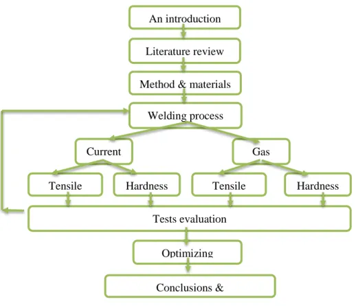
This study aims to optimizing and investigation in TIG welding parametric influence on tensile strength of dissimilar metals SS-304 and low carbon steel. This process will be done utilizing theoretical and experimental work. The theoretical study focuses on the Tungsten Inert Gas (TIG) welding process with dissimilar metals that done includes a literature review and survey. Which study the effect of the tungsten inert gas (TIG) welding parameters. Where, this research focuses on current and welding speed parameters. In addition, study the effect of this parameters on the tensile strength property. The experimental work divided to welding process with different welding parameters, then study the effect of this change in the produced welded. Figure 1.2 shows the research methodology with details.
Figure 1.2. The research methodology.
1.6 SCOPE OF WORK
This study is an experimental study aims to optimizing and investigation in TIG welding parametric influence on tensile strength of dissimilar metals SS-304 and low carbon steel. The study divided to two parts, which are theoretical part represented by first and second chapters. In addition, the experimental part, which represented by third and fourth chapters, and finally fifth chapters which includes the study conclusions and recommendations. The details of all parts are following:
Part One is an introduction, which includes the research overview, research aims,
importance, expected contributions, research methodology, and research scope.
Part Two is literature review, which includes welding classification, methods. TIG
welding process discretion, and equipment.
Part Three is research methodology, which includes experimental started with
material selection as SS 304 chemicals composition and mechanical properties. then Tests evaluation
Optimizing
Conclusions &
Tensile Hardness Tensile Hardness
An introduction
Literature review
Method & materials
Welding process
low carbon steel chemical composition and mechanical properties. followed by equipment and tools of welding and testing equipment.
Part Four is results and discussions, which includes overview, then welding process
and testing.
Part Five is conclusions and recommendations, which includes the research finding
and future recommendations.
PART 2
LITERATURE REVIEW 2.1 WELDING
The welding is a technical process that aims to connect two pieces in an unbreakable manner by creating a link between the two surface to be connected. This is done either with or without fusion of the edges of the two pieces, by causing spastic reactions without heating, or with heating of the two pieces and by causing spastic reactions in the two adjacent surfaces to be combined [14].
2.1.1 Classification of Welding Types
There are different characteristics of the classification of welding types, but the most common are: the type of power used in welding, and the condition of the metal in its area during the course of the work. Welding types are classified according to the type of energy used in the following groups [15, 16]:
1. Mechanical welding methods:
It uses mechanical energy that causes spastic reactions in the welding zone, which are sufficient to obtain the welded link. The mechanical welding methods are:
Cold welding
Explosion welding
Frictional welding
2. Chemical Welding Methods
In which the chemical energy is converted to heat in which the metal reaches fusion without any external pressure. One of these methods are:
Fusion welding
In which the electrical energy turns to heat to melt the edges of the pieces to be soldered. The electrical welding methods include the following [17, 18]:
Manual or semiautomatic welding
Electrostatic welding by spreading high heat when passing Electric current [19].
Electronic welding
Welding with high frequency electric current
Laser welding
4. Electromechanical welding methods
In which the electric energy is converted to heat that using to heat the metal below the fusion state, followed by the shedding of external pressure forces to cause sparks in the surfaces of the two pieces to connect them, the electromechanical welding methods including the following:
The method of electrically soldering (resistance welding)
5. Chemical-mechanical welding methods
In which the chemical energy is converted to heat that utilizing to heat the edges of the two pieces to be reached to the desired degree of welding without melting point also followed by the effect of spandex in the heated metal by putting external pressure forces on the two pieces to be connected, the chemical-mechanical welding methods includes [20]:
Gas welding and compression
On other hand, if the classification is according to the condition of the metal in the weld area during the welding process, all welding types are classified into two large groups:
Figure 2.1 shows the most common classification of welding according to (Welding processes handbook) [14].
Figure 2.1. The most common welding methods [14].
1. Pressure Welding Methods
The welding process takes place at a temperature below the melting point of the metal to be welded. By external pressure, the two pieces can be welded in solid state, provided that these pressures are sufficient to cause spindle reactions in the surfaces of the two parts to be connected [21, 22].
Friction welding
Cold Welding,
Gas welding and pressing,
Welding electrodes,
Welding spread,
Explosion welding,
Ultrasonic welding
2. Fusion welding method
Welding is applied by smelting the edges of the pieces to be soldered, and the welding is done without external pressure. This group includes [23-25]:
Gas smelting welding,
Thermite welding,
Welding in the middle of protective gases,
ARC welding,
Plasma welding,
Electron beam welding,
Laser welding,
Atomic hydrogen welding,
Underwater welding.
2.1.2. Some Welding Methods 2.1.2.2 Frictional Welding
Friction welding is a method of pressure welding, the edges of the two pieces to be connected to the heat that heated by the surface friction of these two pieces, when one rotates in contact with the other, which is fixed with an increased axial pressure force, as well as a certain speed of rotation and pressure is reached, the welding process is done. Friction welding is widely used in welding pre-combustion chambers in diesel engines, rotary assemblies, coupling rods, cylinders, axial couplings, motor vehicle front axles, injection shafts, etc.
In general, friction welding is limited to circular or close sections such as hexagonal and hexagonal shapes. This cannot be sold with circular sections with more than one central axis. The pieces to be welded by the welder must withstand the wicking of the wicks and the high axial forces and resist shocks. Generally, pressing both parts together drives the part of the workpiece at a controlled speed. If the required amount of heat is generated after a preset time, the drive is disengaged and the rotation stops, which the main mechanism of friction welding as shown in Figure 2.2.
Figure 2.2. The motor driving of friction welding [14].
2.1.2.3 Cold Welding
This method is one of the methods of pressure welding, and in this way to obtain welding links by causing a large spastic reaction in the surfaces of the two pieces to be connected without any external heating of these pieces. The two plates are to be welded together and held with two handles to prevent swelling when the plates are pressed to squeeze. They are compressed by a hardened metal capsule from the metal for meat is placed.
The metal is exposed to high pressure. The metal flows in the pressure zone between the surfaces of the two plates and cracks under the influence of the metal flow. Between the points of the two surfaces, the solid bonding. The amount of elastic reactions to be generated at the two interface surfaces is related to the properties of the welded metal, the nature of the oxide crusts and the manner in which these reactions occur.
2.1.2.4 Gas and Pressing Welding
The welding principle is similar to the pressing welding, but the heating of the parts to be sold in this way is done by the flame resulting from gas combustion, the flame can be controlled and focused precisely on the points to be heated before pressing it. The heating is either done gradually by pressing the hot spot, or heating the section to be fully welded with pressure at the same time. In the second case, the section is heated only sideways or heated edges; if the heating from the side can apply pressure on the pieces during the heating of flame, but if the edges are heated only, the flame must be removed before putting pressure on the pieces. Since the flame is removed at
a short interval until the moment of pressure, the surface of the edges is oxidized by the oxygen in air. The heating of these edges must be carried out until the melting state, in order to oxidize the surface oxidized outside the welding area when the pressure is applied, the surface is completely free of oxides.
2.1.2.5 Resistance Welding
Resistance butt welding can be done with applying a pressure, as shown in Figure 2.3. The welding process is heated by the soldering material in an electrical resistance method. Very high temperature is generated when an electrical current passes through the contact surfaces between the two pieces. In the first stage, the mechanical pressure of the two pieces is raised to achieve contact between the two surfaces. In the second stage, the current is connected while the pressure remains constant. In the third phase, the current is cut off and the pressure is increased, gradually reduced and the connection is cooled. There are many methods of resistance soldering such as spot welding and others, where each of which has its own technique, features and multiple use areas [26, 27].
Figure 2.3. Resistance butt welding [14].
2.1.2.6 Explosion Welding
It is modern methods of special pressure welding. It is usually attributed to the group of mechanical methods of metal welding. The chemical energy produced by the transformation of the energy of the explosive material is converted into mechanical
tiling metal layers, leading to the formation of the welding link, and the elasticity of the effect changes to the heat of the heating of the metal to high temperatures. This causes the fluid to flow into the metal under pressure and the appearance of a speeding vehicle. The metal of the surface layers of both parts collides to distort the specified direction at high speed. The two surfaces are bounded to one another to the maximum extent [20, 28].
Figure 2.4. Applying plating to a billet by explosion welding [14].
The other surface oxides and dirt are crushed and collected in a certain area of the two surfaces. The future prospects and areas of the use of explosion welding can be used to form solid bondin9g links in their solid state, as well as the speed of the welding process and on very large surfaces. For example, weld joints with a surface area of 1-20 square meters can be made.
2.1.2.7 Ultrasonic Welding
Ultrasonic waves are used in welding for different purposes. The effect of these waves in the molten weld basin during crystallization can improve the mechanical properties of the weld link by reducing the size of the metal beads and releasing the gases better. Ultrasound can be a source of energy, with the aim of making point or point welding connections. These waves can break down natural and artificial crusts, allowing them to be used in welding metals whose surfaces are coated with oxides, paint layers or others. This method is widely used in the electronic industry, and it has developed rapidly in the plastic industry. High-quality plastic connections can be obtained. The welding of plastic materials with other welding methods is difficult or sometimes impossible. The connection resulting from ultrasonic welding is the result
of a combined effect of mechanical vibrations with high frequencies and relatively small pressure forces. The process of welding ultrasonic usually under the influence of three factors: high frequency vibrations, pressure, thermal effect that accompanies the welding process [20, 23, 29].
2.1.2.8 Thermite Welding
This method is used mainly to weld some parts of machines or installations directly at the work site. The heat diffusing reaction, the result of the reaction of iron oxide with aluminum (aluminum thermite), is the source of welding heat, because the iron oxide mixture is a highly combustible mixture. It has been observed that this reaction occurs at a very rapid rate; large amounts of up to one or more tons of magma can be obtained in one reaction in as little as 30 seconds. Figure 2.5 shows the mold set for thermite welding. The thermite welding process is widely used in railways industry [30, 31].
Figure 2.5. Mold set for thermite welding [14].
2.1.2.9 Gas-Smelting Welding (Gas Welding)
gases are regulated to produce flame. Various gases, including acetylene, domestic gas, methane, propane, hydrogen and gasoline vapor, are used.
Gas welding is especially suitable for connecting metal sheets with thicknesses between 2 and 50 mm. Its uses today are limited to welding panels with thicknesses ranging from 1 to 10 mm, and may be used in cases where the locations of the joints to be welded are not easily accessible.
2.1.2.10 ARC Welding
The electric arc welding method is superior to all other methods, up to 90% of the total use of different smelting methods. In this way, the electric energy is converted into thermal energy used in the local fusion of the two ends of the joint. Figure 2.6 shows the schematic diagram of manual ARC welding process.
Figure 2.6. Manual metal arc welding [14].
2.1.2.11 Electron Beam Welding
The main advantage of the process of electronic radiography is the use of the energy of electrons that move very fast in the middle of the vacuum, as shown in Figure 2.7. When these electrons hit the metal surface, most of their kinetic energy is converted to heat used to melt the metal. If electronic radiation is used as a heat source for welding, it is essential to obtain free electrons, then assemble them in a pack and give very high speeds to increase their kinetic energy. This energy is then transformed into heat when the electron enters the metal to be sold.
Figure 2.7. The electron gun [14].
2.1.2.12 Laser Welding
Quantum generators appeared in the second half of the 20th century. It can obtain high-intensity photovoltaic beams and focus their energies on areas no more than a thousandth of a millimeter. On this basis, in the present era, laser irradiation devices are used for welding, cutting and various heat treatments, as shown in Figure 2.8. Quantum generators convert electrical, chemical, photovoltaic, and thermal energy into ordinary photovoltaic radiation waves [31].
2.1.2.13 Atomic Hydrogen Welding
The metal is smelted in this way by the heat released as a result of the transformation of the atomic hydrogen into a molecular, and the burning heat of the arc between the two electrodes of tungsten. The amount of heat generated by arc radiation and the combustion of hydrogen particles in the outside area of the torch is very small when compared to the amount of heat released by hydrogen atoms hitting the metal and turning it into molecular hydrogen.
2.1.2.14 Underwater Welding
This method of modern and special welding methods, designed from the ability of the electric arc to ignite balanced in the bubble gas and because of the intensive cooling of the water surrounding this arch. The gas bubble is formed by evaporation of the water and dissolved into hydrogen and oxygen, as well as the gases formed by the fusion of the electrode metal and the coating layer [20, 32].
2.2 TIG WELDING 2.2.1 Process Discretion
Gas tungsten arc welding (GTAW) is another name for TIG welding, which means ARC collisions between the non-consumable tungsten electrode and the workpiece. The inert gas is protected from the welding electrode and electrodes. Usually, argon is provided by a gas cup at the end of the welding gun where the central electrodes are located. Figure 2.9 shows the schematic diagram of Gas tungsten ARC welding equipment.
In general, TIG welding can also be used for welding with manually applied fillers, similar to gas welding. TIG welding mechanical tools are used in applications such as connecting tubes and welding tubes to final plates of heat exchangers, and these automatic welding tools can incorporate many advanced features, including the mechanical supply of filler wires. This method has the following characteristics:
Stable ARC
Excellent control of weld results.
The main uses of TIG welding are light metal welding such as aluminum and magnesium alloy, copper welding and stainless steel welding. It is also suitable for welding all kinds of connections and all welding positions, except for lead and zinc. Additionally, TIG welding is more suitable for thin materials from about 0.5 nm to about 3 nm. Whereas, TIG welding cannot compete with methods such as short arc welding, in terms of productivity [14, 33].
2.2.2 Equipment
The main required equipment for TIG welding are as following:
Power
High frequency, which a generator for ARC ignition
Welding gun
Control equipment
Shielding gas
2.2.2.1 Power
usually, the TIG welding is done utilizing DC, and the cathode is connected to the electrode, so most of the heat is generated in the work piece. In aluminum welding, the oxide layer breaks only when the electrode is connected to the anode, which eventually results in an excessive temperature of the electrode. The aluminum and magnesium are typically welded to AC as a compromise.
voltage should be around 80V. The HF generator is always engaged. Otherwise, when welding with AC (sinusoidal), and at the zero crossing the arc is turned off.
Square wave AC
Based on new technologies related to square waveforms, several new power source designs emerged in the 1970s. This means that zero crossing is very fast and has the following effects:
Generally, continuous HF ignition voltage is not required for AC TIG welding.
By allowing the ratio of anode and cathode currents to be variable, it is possible to control penetration and oxide breakdown just as when aluminum is welded.
Figure 2.10 shows the current waveform for a square wave supply. The equilibrium curve (left) has very fast zero crossing as opposed to the existing sine wave. The ability to switch the balance between the two polarities means that the welding speed can increase by 50-75%. General setting for a balanced waveform has a 50% cathode on the electrode. The two curves on the right are 130% positive polarity, which are faster penetration rate or speed, of 70% sound and 155% positive, which are negative oxide breakdown, of 45% positive sound. Figure 2.11 shows the pulse TIG requires principle that the weld pool be solidify in between pulses [14].
Figure 2.10. The TIG welding balance control and square wave [14].
Figure 2.11. The pulse TIG requires principle that the weld pool be solidify in between pulses [14].
2.2.2.2 Welding Gun
The welding guns is the basic requirement for TIG welding, which must be easy to handle and well insulated through welding process. Requirements apply to manual welding, but for machine welding, its less important. There are two main types of welding guns:
1. Water cooling and 2. Air coolers.
Figure 2.12 shows the TIG welding gun example. In fact, the current welding guns of these two types can deliver the following welding currents:
Water cooling: Up to approx. 400 A
Air cooling: Up to approx. 200A.
Figure 2.12. TIG welding gun example [14].
2.2.2.3 Control Equipment
The required control equipment depends on the degree to which the welding process is mechanized. It is common that the pre-flow and post-flow of the shielding gas and the HF generator are controlled automatically. The ability to charge craters and
PART 3 EXPERIMENTAL 3.1 MATERIAL SELECTION
3.1.1 Stainless Steel
The house or kitchen is not without stainless steel utensils that are strong and resistant to rust and chemicals in foods and beverages, the high resistance of stainless steel made it an ideal material suitable for industrial, scientific and military uses. Stainless steel is called "stainless steel" and is a combination of several metals (metal alloy) consisting of: iron, chromium, nickel, molybdenum and carbon. The proportions of these metals vary to give several types of stainless steel, sometimes may be added metals or other materials such as magnesium, copper or nitrogen in order to give it special characteristics.
Types of stainless steel
Stainless steel is divided by composition into four main groups that differ from each other in their corrosion resistance and mechanical properties as well as their cost and in industrial use.
1. Duplex stainless steel 2. Martensitic stainless steel 3. Austenitic stainless steel 4. Ferritic stainless steel
3.1.1.1 SS 304
stainless steel. From a chemical point of view, 304 stainless steel containing 8% nickel
and 18% chrome. In addition, 316 stainless steel containing 2% molybdenum, 10% nickel and, 16% chrome. In fact, adding molybdenum is to arising resist corrosion and rust.
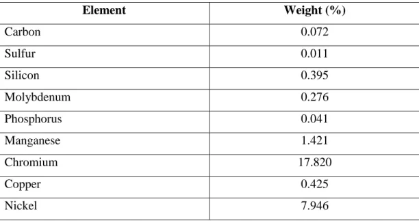
3.1.1.2 Chemicals Composition of SS 304
Table 3.1. The chemical composition of SS-304.
Element Weight (%) Carbon 0.072 Sulfur 0.011 Silicon 0.395 Molybdenum 0.276 Phosphorus 0.041 Manganese 1.421 Chromium 17.820 Copper 0.425 Nickel 7.946 3.1.1.3 Application of SS 304
Common uses for 304L stainless steel:
304 stainless steel is the most common form of stainless steel, and the strength of 304 stainless steel makes it easy to sterilize, thus it is ideal for use with food packaging machines.
It is also used in forming and cutting cars, wheel covers, hose clips and any equipment that needs to be made of stainless material such as storage tanks, pressure vessels and pipes.
One of the drawbacks of using stainless steel 304 is that it is prone to corrosion when exposed to chloride solution, so it is best to use stainless steel 316 in the packaging machinery if the product can cause a chemical reaction
3.1.1.4 Mechanical Properties of SS 304
Table 3.2. The mechanical properties of SS-304.
Property Value
Density 8.21 kg/m
Yield strength 293 MPa
Tensile strength 500-750 MPa
Elastic modulus 195-210 MPa
Hardness 84 max
Elongation 50%
3.1.2 Carbon Steel
Carbon steel is a metallic alloy consisting of two elements, iron and carbon, as well as other elements in very small quantities such as sulfur, phosphorous, manganese, nitrogen, silicon, and copper to influence mechanical properties. Carbon is a vacuum defect of iron which forms a solid solution with all forms of single-phase iron. All of these changes are visible along the left vertical axis of the diagram phase.
3.1.2.1 Low Carbon Steel
All steel is carbon steel. Carbon steel is used to denote carbon steel as the main alloy. The properties in carbon steel are determined primarily by the amount of carbon percentages. For these alloys, no other quantities of alloy elements such as chromium, manganese, cobalt and tungsten have been identified. Based on the carbon content =, there are four types of carbon steel.
Low carbon Steel (0.05–0.29% carbon)
Medium carbon Steel (0.30–0.59% carbon)
High Carbon Steel (0.6-0.99% Carbon)
Very High Carbon Steel (1.0 2.0% Carbon)
It increases hardness and increases carbon content. They can undergo successful thermal treatment. Therefore, this is usually a very strong and difficult, but the ductility can be low.
Mild steel with small amounts of carbon between 0.16 and 0.3%. It is therefore a low carbon steel that contains very little carbon. It is difficult to distinguish between mild steel or not with the naked eye, since it belongs to the errors of fine geometry. Mild steel is "soft and formable", cheap material with good weldability, portability, low temperature elongates crisp shift. They are used in cars, trucks, hull, bridges and other structures that are designed to handle large amounts of stress or anything that requires a huge amount of steel. It is usually used as rails or for beams, also called "structural steel" at times.
3.1.2.2 Chemical Composition of Low Carbon Steel
Table 3.3. The chemical composition of low carbon steel.
Element Weight % Nickel 0.021 Manganese 1.342 Carbon 0.297 Aluminum 0.031 Sulfur 0.007 Silicon 0.241 Phosphorus 0.023 Copper 0.019 Chromium 0.022 Molybdenum 0.010
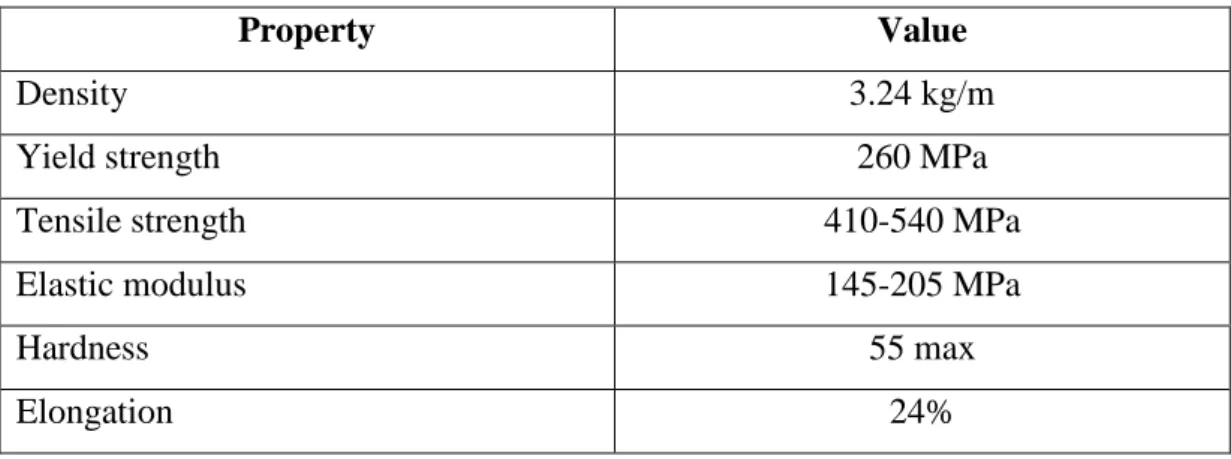
3.1.2.4 Mechanical Properties of Low Carbon Steel
Table 3.4. The mechanical properties of Low Carbon Steel.
Property Value
Density 3.24 kg/m
Yield strength 260 MPa
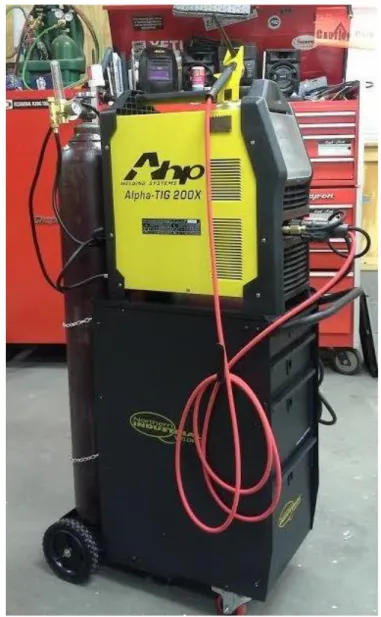
3.2 EQUIPMENT AND TOOLS 3.2.1 TIG Welding Machine
This welding machine adopts rectifiers designed with advanced inverter technology. Introduction of TIG inverter welding is derived from theory and inverter power devices. The TGB welding power of the high-power IGBT inverter is used to convert the working frequency from 50 / 60Hz to high frequency (20kHz or more). Then the current is regulated while voltage is reduced. A strong DC power source can be produced using PWM technology. The size and weight of the inverter welders are greatly reduced, while the efficiency increases by 30% compared to the old transformer-based welders.
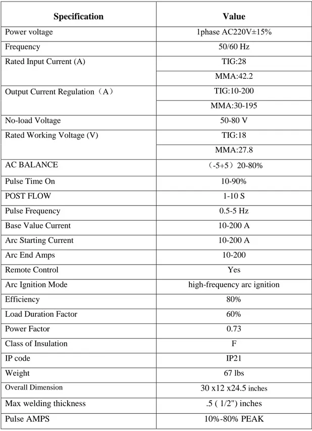
Table 3.5. Alpha-TIG200X specifications
Specification Value
Power voltage 1phase AC220V±15%
Frequency 50/60 Hz
Rated Input Current (A) TIG:28
MMA:42.2
Output Current Regulation(A) TIG:10-200
MMA:30-195
No-load Voltage 50-80 V
Rated Working Voltage (V) TIG:18
MMA:27.8
AC BALANCE (-5+5)20-80%
Pulse Time On 10-90%
POST FLOW 1-10 S
Pulse Frequency 0.5-5 Hz
Base Value Current 10-200 A
Arc Starting Current 10-200 A
Arc End Amps 10-200
Remote Control Yes
Arc Ignition Mode high-frequency arc ignition
Efficiency 80%
Load Duration Factor 60%
Power Factor 0.73
Class of Insulation F
IP code IP21
Weight 67 lbs
Overall Dimension 30 x12 x24.5 inches
Max welding thickness .5 ( 1/2") inches
3.2.3 Testing Equipment 3.2.3.1 Hardness Test Machine
Figure 3.3. ZONHOW LHRS-150 Rockwell Hardness.
3.2.3.2 Tensile Test Machine
Servo-hydraulic load frames – HB series, 2-column
In a closed force flow, Two-column load holders are designed to test materials and components under dynamic load. During normal operation, the frame is supported by vibration isolation leveling units so that no noticeable forces are sent to the ground. When environmental conditions or tests are critical in nature, it is advisable to use the available air chambers optionally; these have a normal frequency of about 3-6 Hz. Table 3.5 shows the specifications of the tensile testing machine.
Figure 3.4. Servo-hydraulic load frames – HB series, 2-column tensile test machine Table 3.5. Tensile test machine Specification.
Dynamic nominal
force 50 100 250 500 kN
Crosshead clamping
electrohydraulic electrohydraulic electrohydraulic electrohydraulic
Crosshead adjustment
electrohydraulic electrohydraulic electrohydraulic electrohydraulic
AG100 – max. test-frame height with 100mm-stroke actuator
3175 (3675)1) 3259 (3759)1) 3523 (4023)1) 4045 (4545)1) mm
AG250 – max. test-frame height with 250mm-stroke actuator
3475 (3975)1) 3559 (4059)1) 3823 (4323)1) 4345 (4845)1) mm
test-A – max. column height 2690 (3190) 1) 2690 (3190)1) 2900 (3400)1) 3250 (3750)1) mm AK - tilted dimension for installation 2820 (3320)1) 2820 (3320)1) 3060 (3560)1) 3500 (3980)1) mm B — max. width of test frame 1079 1079 1197 1525 mm C – max. depth of test frame 780 (1020) 2 780 (1020)2) 1130 (1130)2) 1130 (1370)2) mm D1 – column spacing 565 565 670 800 mm E – column diameter 80 80 100 120 mm F - height of top edge of lower crosshead3) 950 950 890 900 Mm
G – max. test area
height4) 1510 (2010)
1) 1510 (2010)1) 1705 (2205)1) 2120 (2620)1) mm
H – max. working
test area height5) 1434 (1934)
1) 1434 (1934)1) 1614 (2114)1) 2020 (2520)1) mm J - crosshead displacement range 1000 (1250) 1) 1000 (1250)1) 1150 (1400)1) 1250 (1400)1) mm Weight without T-slotted platform6) 899 (945) 1) 895 (941)1) 1361 (1430)1) 3660 (3780)1) Kg Weight with T-slotted platform6) 1137 (1182) 1) 1133 (1178)1) 2082 (2232)1) 4860 (4980)1) kg
Frame stiffness with crosshead separation 1000 mm7)
730 730 988 1529 kN/mm
Frame stiffness with crosshead separation 1000 mm2
870 870 1332 1848 kN/mm
Item No.
Standard height 077533 924779 040159 079720
Standard height with
T-slotted platform 077370 079752 040158 079728 Extra-high + 500 mm 750972 077534 079755 079721 Extra-high + 500 mm with T-slotted platform 077535 079753 079756 079733
PART 4
RESULTS AND DISCUSSION 4.1 OVERVIEW
This chapter showing the welding process of dissimilar metals with mechanical testing and evaluations.
4.2 WELDING PROCESS
The welding process has been done utilizing Alpha-TIG200X TIG welding machine, before that the welding process has been designed using Minitab software.
4.2.1 The Preparation of Samples
low carbon steel and SS-304 plates has been prepared with the dimensions of 100×25×6 mm, as well as with the bevel heights of 6 mm, and bevel angle of 45°. For welding, specimens are welded with a root gap distance 2 millimeter as shown in Figure 4.1.
4.2.1.1 Samples Geometry
4.2.2 Welding
4.2.2.1 Welding Process Design
The Minitab program is one of the most powerful statistical programs with wide applications in the analysis of scientific research data in various fields. It was originally designed by Pennsylvania State University researchers in 1972. (Barbara F. Ryan, Thomas A. Ryan, Jr., and Brian L. Joiner). This program is characterized by ease of use, accuracy of calculations, and comprehensive statistical tools provided by the basic statistics, regression and variance analysis, quality tools, experimental design, control schemes and others.
Second step choosing taguchi design method, then selecting type of design, which is 3-level design. In addition, number of factors. the welding factors are welding current and Gas flow rate. Figure 4.3 shows the select Stat/DOE/Factorial/Create Factorial Design.
Welding parameters as resulted by Minitab software shown in Table 4.1. Table 4.1. Welding process parameters
Experiment no. Gas flow Rate (Lit/min) Current (Amp)
1 8 80 2 8 100 3 8 120 4 10 80 5 10 100 6 10 120 7 12 80 8 12 100 9 12 120
Table 4.2. welding process parameters.
Parameter Range
Distance from tip to contact 4 mm
Voltage 10-15
Tungsten electrode 2.4 Diameter
Filler rod SS-304 1.6 mm Diameter
Gas flow rate Argon 8-12 L/M
4.3 TESTING 4.3.1 Tensile Test
Per ASTM standard has been used to tensile test, where size of the work piece is decided as per ASTM A370. Figure 4.7 shown welding sample prepared after machining. Table 4.3 shows tensile test results according to welding parameters. As showing, the best tensile test results recorded by sample No. 3, which welded by (8 gas flow rate and 120 current Ampere). Followed by sample No. 9 that welded by
Table 4.3. The tensile test results.
Experiment no. Gas flow Rate
Lit/min
Current Amp Tensile Strength
N/MM2 1 8 80 449.82 2 8 100 465.21 3 8 120 596.59 4 10 80 488.56 5 10 100 479.11 6 10 120 456.81 7 12 80 519.64 8 12 100 440.62 9 12 120 556.19 4.3.1.1 Taguchi Analysis
Table 4.4 shoes the S/N ratios and Mean 1 of Tensile Strength resulted by Minitab software.
Table 4.4. The tensile test results.
Experiment
no. Gas flow Rate Lit/min Current Amp Tensile Strength N/MM2 SNRA1 MEAN1 1 8 80 449.82 53.0608 449.82 2 8 100 465.21 53.3530 465.21 3 8 120 596.59 55.5135 596.59 4 10 80 488.56 53.7784 488.56 5 10 100 479.11 53.6087 479.11 6 10 120 456.81 53.1947 456.81 7 12 80 519.64 54.3141 519.64 8 12 100 440.62 52.8813 440.62 9 12 120 556.19 54.9045 556.19
Mean
Table 4.5 shows the graph of the main effects of the signal-to-noise ratios of the tensile strength, as shown in Table 4.5, while Table 4 shows the means response table. Figure 4.7 shows the main media effects according to gas and current flow.
Table 4.5. Response Table for Signal to Noise Ratios Nominal is best (10×Log10(Ybar^2/s^2))
Level Current GAS Flow Rate
1 * *
2 * *
3 * *
Delta * *
Rank 1.5 1.5
Table 4.6. Response Table for Means
Level Current GAS Flow Rate
1 503.9 486.0
2 474.8 461.6
3 505.5 536.5
Delta 30.7 74.9
Figure 4.7. The main effects of means.
From Figure 4.7, it can be note that gas flow rate is highly effective as compared to the current.
Signal to Noise Ratios
The signal-to-noise ratio was calculated using Minitab, as Table 4.7 shows the response-to-noise-response schedule. Figure 4.8 illustrates the main effects of SN ratios for a tensile test. It can be note that gas flow rate is highly effective as compared to the current.
Table 4.7. Response Table for Signal to Noise Ratios Larger is better
Level Current GAS Flow Rate
1 53.98 53.72
2 53.53 53.28
3 54.03 54.54
Delta 0.51 1.26
Rank 2 1
Figure 4.8. The main effects of SN ratios.
ANOVA Test
As same as Mean and S/n ratio, the ANOVA test has been done to carried out the highly effective factor (current or gas flow rate). Table 4.9 shows the factor information of tensile test, which is found that welding current is highly effective by
Table 4.9. The Factor Information of tensile test.
Factor Type Levels Values
Current Fixed 3 80, 100, 120
GAS Flow Rate Fixed 3 8, 10, 12
Table 4.10. Analysis of Variance of tensile test by ANOVA Test.
Source DF Adj SS Adj MS F-Value P-Value
Current 2 1786 893.1 0.30 0.754
GAS Flow Rate 2 8754 4376.8 1.49 0.329
Error 4 11770 2942.5
Total 8 22310
4.3.2 Hardness Test
The hardness test has been done on Rockwell hardness tester by pointer used 1/16”, and force applied 100 kg. the best results recorded by sample No. 9 by 116 in weld metal and HAZ with (12 Gas flow rate and 120 welding current ampere).
Table 4.11. The hardness test results
Experiment No. Gas
flow Rate Lit/min Current Amp Hardness Bas Metal HAZ Weld Metal 1 8 80 97 99 101 2 8 100 96 99 103 3 8 120 96 101 107 4 10 80 95 99 108 5 10 100 97 102 104 6 10 120 96 103 113 7 12 80 95 103 108
8 12 100 95 101 114
9 12 120 97 106 116
4.3.2.1 Taguchi Analysis
Table 4.12 shows the S/N ratios and Mean 1 of hardness test resulted by Minitab software.
Table 4.12. The Hardness Signal to Noise Ratio.
Experiment No. Gas flow Rate Lit/min Current Amp Hardness
Weld Metal SNRA1 MEAN1
1 8 80 101 40.0864 101 2 8 100 103 40.2567 103 3 8 120 107 40.5877 107 4 10 80 108 40.6685 108 5 10 100 104 40.3407 104 6 10 120 113 41.0616 113 7 12 80 108 40.6685 108 8 12 100 114 41.1381 114 9 12 120 116 41.2892 116 Mean
Table 4.13 shows the response schedule for signal to noise ratios, and Table 4.14 shows the means response table. Figure 4.9 shows the main media effects according to gas and current flow. From figure, it can be note that welding current is highly effective as compared to the gas flow rate in hardness test.
Table 4.13. Response Table for Signal to Noise Ratios Nominal is best (10×Log10(Ybar^2/s^2))
Level Current GAS Flow
Rate 1 * * 2 * * 3 * * Delta * * Rank 1.5 1.5
Table 4.14. Response Table for Means
Level Current GAS Flow Rate
1 103.7 105.7
2 108.3 107.0
3 112.7 112.0
Delta 9.0 6.3
Rank 1 2
Signal to Noise Ratios
Signal to Noise Ratios has been calculated using Minitab software, where Table 4.15 shows response Table for Signal to Noise Ratio of hardness test. Figure 4.10 shows the main effects of SN ratios of hardness test. It can be note that welding current is highly effective as compared to the gas flow rate.
Table 4.15. Response Table for Signal to Noise Ratios Larger is better.
Level Current GAS Flow Rate
1 40.31 40.47
2 40.69 40.58
3 41.03 40.98
Delta 0.72 0.51
ANOVA Test
As same as Mean and S/n ratio, the ANOVA test has been done to carried out the highly effective factor (current or gas flow rate) in hardness test. Table 4.16 shows the factor information of hardness test, which is found that welding gas flow rate is highly effective by recording 0.0.083 as P-Value, while welding current recorded 0.0.033.
Table 4.16. The Factor Information of hardness test.
Factor Type Levels Values
Current Fixed 3 80, 100, 120
GAS Flow Rate Fixed 3 8, 10, 12
Table 4.17. The Analysis of Variance of hardness test by AVOVA Test.
Source DF Adj SS Adj MS F-Value P-Value
Current 2 121.56 60.778 8.97 0.033
GAS Flow Rate 2 66.89 33.444 4.93 0.083
Error 4 27.11 6.778
PART 5 CONCLUSIONS 5.1 CONCLUSIONS
This study aims to improve and verify the parametric effect of TIG welding on the tensile strength of various metals SS-304 and low carbon steel. This process will be carried out using theoretical and experimental work. In addition, the research aims to study various metal connections using the metal filling process. In general, different welding is used to make thermal power plants, pressure vessels and tubes in nuclear reactors and heat exchangers, and therefore, failure often occurs due to low tensile strength. The process designed using Minitab software. After survey and experimental work, there are some points that can be concluded, which as following:
The best tensile test results recorded by sample No. 3, which welded by (8 gas flow rate and 120 current Ampere).
In mean and Signal to Noise Ratios of Tensile Strength, it can be note that gas flow rate is highly effective as compared to the current. while in ANOVA Test of Tensile Strength is found that welding current is highly effective by recording 0.754 as P-Value, while gas flow rate recorded 0.329.
The best hardness results recorded by sample No. 9 by 116 in weld metal and HAZ with (12 Gas flow rate and 120 welding current ampere).
In mean and Signal to Noise Ratios of hardness, the main effects of SN ratios of hardness test. It can be note that welding current is highly effective as compared to the gas flow rate. While in ANOVA Test, is found that welding
gas flow rate is highly effective by recording 0.0.083 as P-Value, while welding current recorded 0.0.033.
5.2 FUTURE RECOMMENDATIONS
As future recommendation, these are some points that can be taken in the accounts:
This work can be extended to study the effect of parameter on other responses such as heat affected zone (HAZ) and mechanical properties.
This study could be applied on other metals.
This study could be applied on other welding processes.
This study could be used as references on study the effect of welding parameters on the heat affected zone, hardness and distortion.
REFERENCES
1. C. Lonsdale and M. Engineer, "Thermite rail welding: history, process developments, current practices and outlook for the 21st century," in Proc.
AREMA 1999 Annu. Conf., 1999, p. 18.
2. X.-L. Gao, L.-J. Zhang, J. Liu, and J.-X. Zhang, "A comparative study of pulsed Nd: YAG laser welding and TIG welding of thin Ti6Al4V titanium alloy plate," Materials Science and Engineering: A, vol. 559, pp. 14-21, 2013.
3. P. Mohan, "Study the effects of welding parameters on TIG welding of aluminium plate," 2014.
4. Q. Wang, D. Sun, Y. Na, Y. Zhou, X. Han, and J. Wang, "Effects of TIG welding parameters on morphology and mechanical properties of welded joint of Ni-base superalloy," Procedia Engineering, vol. 10, pp. 37-41, 2011. 5. M. Indira Rani and R. Marpu, "Effect of pulsed current TIG welding
parameters on mechanical properties of J-joint strength of Aa6351," The
International Journal of Engineering And Science (IJES), vol. 1, pp. 1-5,
2012.
6. A. Norman, V. Drazhner, and P. Prangnell, "Effect of welding parameters on the solidification microstructure of autogenous TIG welds in an Al–Cu–Mg– Mn alloy," Materials Science and Engineering: A, vol. 259, pp. 53-64, 1999. 7. A. K. Srirangan and S. Paulraj, "Multi-response optimization of process parameters for TIG welding of Incoloy 800HT by Taguchi grey relational analysis," Engineering science and technology, an international journal, vol. 19, pp. 811-817, 2016.
8. J. Pasupathy and V. Ravisankar, "Parametric optimization of TIG welding parameters using Taguchi method for dissimilar joint (low carbon steel and AA1050)," Journal of Scientific & Engineering Research, vol. 4, pp. 25-28, 2013.
9. O. Greyjevo and A. I. T. METODO, "Optimization of weld bead geometry in TIG welding process using grey relation analysis and Taguchi method,"
Materiali in tehnologije, vol. 43, pp. 143-149, 2009.
10. L. Singh, R. Singh, N. K. Singh, D. Singh, and P. Singh, "An evaluation of TIG welding parametric influence on tensile strength of 5083 aluminium alloy," Int. J. Mech. Aerospace, Ind. Mechatronics Eng, vol. 7, pp. 1262-1265, 2013.
stainless steel," Science and Technology of Welding and Joining, vol. 15, pp. 213-218, 2010.
12. P. R. Singh, D. N. Suri, and J. Randhawa, "Optimization of Process Parameters for TIG welding of 304L stainless steel using response surface methodology," Int. J. Mech. Sci. Civ. Engineeiring, vol. 2, pp. 36-40, 2013. 13. L. Singh, V. Shah, and N. K. Singh, "Study The Influence of TIG Welding
Parameters On Weld Characteristics Of 5083 Aluminum Alloy,"
International Journal of Engineering Science and Innovative Technology,
vol. 2, pp. 102-10, 2013.
14. K. Weman, Welding processes handbook: Elsevier, 2011.
15. P. Kah, H. Latifi, R. Suoranta, J. Martikainen, and M. Pirinen, "Usability of arc types in industrial welding," International Journal of Mechanical and
Materials Engineering, vol. 9, p. 15, 2014.
16. H. G. Mehlhouse, "Welding method," ed: Google Patents, 1938.
17. T. Kitani and H. Goto, "Method for electrical arc welding," ed: Google Patents, 1974.
18. W. C. Rudd and H. N. Udall, "Melt welding by high frequency electrical current," ed: Google Patents, 1975.
19. J. Matsunaga, I. Watanabe, N. Nakao, E. Watanabe, W. Elshahawy, and N. Yoshida, "Joining characteristics of titanium-based orthodontic wires connected by laser and electrical welding methods," Journal of Materials
Science: Materials in Medicine, vol. 26, p. 50, 2015.
20. S. Kou, "Welding metallurgy," New Jersey, USA, pp. 431-446, 2003. 21. S. A. Bagnold, "Cold pressure welding," ed: Google Patents, 1950. 22. S. A. Bagnold, "Pressure welding," ed: Google Patents, 1955. 23. S. E. Walak, "Welding method," ed: Google Patents, 2002.
24. G. Kuhnen, "Method of joining metal parts by fusion welding," ed: Google Patents, 1996.
25. G. E. Trewiler, "Fusion welding method and welded article," ed: Google Patents, 2006.
26. K. Fujii, Y. Goto, M. Ryudo, and H. Ihara, "Resistance welding monitor," ed: Google Patents, 1994.
27. D. J. Spinella and D. Bergstrom, "Resistance welding fastener, apparatus and methods for joining similar and dissimilar materials," ed: Google Patents, 2016.
28. I. Szachogluchowicz, L. Sniezek, and V. Hutsaylyuk, "Low cycle fatigue properties of AA2519–Ti6Al4V laminate bonded by explosion welding,"
Engineering Failure Analysis, vol. 69, pp. 77-87, 2016.
29. C. Shao, T. H. Kim, S. J. Hu, J. J. Jin, J. A. Abell, and J. P. Spicer, "Tool wear monitoring for ultrasonic metal welding of lithium-ion batteries,"
Journal of Manufacturing Science and Engineering, vol. 138, p. 051005,
2016.
30. Z. Mouallif, B. Radi, and I. Mouallif, "Effect of the Inclusion Defect on the Mechanical Behavior of Thermite Welds," Adv. Theor. Appl. Mech, vol. 9, pp. 11-20, 2016.
31. S. E. Walak, "Welding method," ed: Google Patents, 2000.
32. T. Kojima, K. Ohwaki, K. Tsuchiya, and N. Katayama, "Development of underwater welding with high power YAG laser," Ishikawajima-Harima
Giho, vol. 37, pp. 303-308, 1997.
33. P. J. Modenesi, E. R. Apolinario, and I. M. Pereira, "TIG welding with single-component fluxes," Journal of materials processing technology, vol. 99, pp. 260-265, 2000.
![Figure 1.1. The weld bead metal of TIG welding process [9].](https://thumb-eu.123doks.com/thumbv2/9libnet/5400010.101994/17.892.171.789.636.842/figure-weld-bead-metal-tig-welding-process.webp)
![Figure 2.1 shows the most common classification of welding according to (Welding processes handbook) [14]](https://thumb-eu.123doks.com/thumbv2/9libnet/5400010.101994/25.892.187.767.211.511/figure-common-classification-welding-according-welding-processes-handbook.webp)
![Figure 2.4. Applying plating to a billet by explosion welding [14].](https://thumb-eu.123doks.com/thumbv2/9libnet/5400010.101994/29.892.210.753.330.575/figure-applying-plating-billet-explosion-welding.webp)
![Figure 2.5. Mold set for thermite welding [14].](https://thumb-eu.123doks.com/thumbv2/9libnet/5400010.101994/30.892.218.728.590.928/figure-mold-set-thermite-welding.webp)