SN Applied Sciences (2021) 3:364 | https://doi.org/10.1007/s42452-021-04371-4
Improving the surface quality and mechanical properties of selective
laser sintered PA2200 components by the vibratory surface finishing
process
Hamaid M. Khan1 · Tolga B. Sirin2 · Gurkan Tarakci1 · Mustafa E. Bulduk1 · Mert Coskun1 · Ebubekir Koc1 ·
Yusuf Kaynak2
Received: 16 October 2020 / Accepted: 11 February 2021 © The Author(s) 2021 OPEN
Abstract
This paper attempts to improve the physical and mechanical properties of selective laser sintered polyamide PA2200 components through a vibratory surface finishing process by inducing severe plastic deformation at the outer surface layers. The industrial target of additive manufacturing components is to obtain structures having surface roughness, hardness, and other mechanical properties equivalent to or better than those produced conventionally. Compared to the as-built SLS PA2200 samples, vibratory surface finishing treated specimens exhibited a smooth surface microstruc-ture and more favorable roughness, hardness, and tensile strength. Also, the duration of the vibratory surface finishing process showed a further improvement in the surface roughness and hardness of the SLS samples. Compared to the as-built state, the roughness and hardness of the surface-treated samples improved by almost 90% and 15%, respectively. Consequently, microstructural analysis indicates that lower surface roughness and enhanced surface hardness is a crucial factor in influencing the overall tensile strength of SLS-PA2200 components. We consider that the combination of VSF and SLS processes can successfully handle a wide range of potential applications. This study also highlights the efficiency and applicability of the vibratory surface finishing process to other additive manufacturing processes and materials.
* Hamaid M. Khan, [email protected]; [email protected] | 1Fatih Sultan Mehmet Vakif University, Aluminum Test Training,
and Research Center, Beyoglu, 34420 Istanbul, Turkey. 2Department of Mechanical Engineering, Technology Faculty, Marmara University,
Graphic abstract
Keywords Mechanical treatment · Selective laser sintering · Additive manufacturing · Surface roughness · Hardness · Mechanical strength
1 Introduction
Selective laser sintering (SLS) is a type of additive manu-facturing (AM) process, which sinter powder particles to melt and fuse their outer surfaces to form a solidified structure [1]. In order to form a three-dimensional geom-etry, the laser sintering process is repeated on several lay-ers of powder particles, which are stacked up one over the other according to a pre-designed computer-aided design (CAD) model [2]. The most common SLS material is Poly-amide PA2200, thermoplastic material with high strength, high melting temperature, chemical resistance, and abra-sion resistance [3]. Compared to the conventional pro-cesses, the SLS is a cost-effective and low material waste technique to create complex forms, which are difficult to fabricate with conventional techniques [4]. The as-built SLS components are known for their light-weight [5], high hardness and excellent yield, and tensile strength com-pared to their conventional equivalents [6]. However, the high micro-irregularities in the form of surface roughness, low ductility, and high sub-surface porosity negatively influence the overall mechanical performance of the SLS parts [7]. Any subsequent development in the choice of processing parameters is inadequate to bring a significant
shift in the overall mechanical and microstructural features [8]. Therefore, the SLS parts are often post-processed to produce a necessary change in their final performance.
The mechanical-based post-processing operations are quite effective in reducing the surface irregularities of the additive components [9]. Besides refining the grain size of the surface, the mechanical impact also alters the grain morphology in the near sub-surface region. This results in forming a protective layer of refined grains on the sur-face, which delays the crack nucleation or its propagation during loading [10]. Herein, the vibratory surface finishing (VSF) process was used to treat the as-built SLS polyam-ide PA2200 samples. The VSF process is a wpolyam-idely adopted practice for the mass finishing of samples fabricated from different materials. Here, the container with many media pellets is subjected to vibratory motion using the weights and electric motor that generate repeated impact of media pellets with the sample’s surface [11]. The interac-tion of the media pellets with the surface can be a mix of transversal and normal impacts. The transversal impact generally favors the mechanical attrition of the surface deviations, and the normal impact results in the trans-ferring of compressive stresses on the surface due to the plastic deformation. As a result, the post-processing using
the VSF process significantly enhances the surface charac-teristics by reducing the surface roughness and improving the mechanical strength [12]. In this study, both cubical and tension test specimens were subjected to different VSF treatment duration for surface integrity enhancement. The final surface quality was then investigated and com-pared with the as-built condition.
This study aims to expose the SLS prepared PA2200 part material to VSF surface treatment at different expo-sure times. This is of interest as the expoexpo-sure times could allow sufficient particle-material interaction, leading to decreased surface porosity and reduced surface rough-ness of the SLS PA2200 material. In this study, tensile test specimens were also created for various times (0 and 4 h) to compare their mechanical properties. The paper is structured as follows; the introduction (Sect. 1) is fol-lowed by materials and method (Sect. 2), highlighting the characterization techniques undertaken in this study. The research and discussion (Sect. 3) are divided into four parts where the effect of vibratory surface finishing was evaluated on the (1) microstructure, (2) surface roughness, (3) hardness, and (4) tensile strength of the SLS prepared polyamide PA2200 components. Finally, the conclusion of the present study was addressed in Sect. 4.
2 Materials and methods
The polyamide PA2200 powders from EOS GmbH were selected to prepare the cubical and tension test specimens on the EOS FORMIGA P110 SLS 3D printing machine. All the samples were produced at the center of the platform bed. The parameters used for the fabrication of the core and contour regions of the SLS samples were 21 W laser power, 2500 mm/s scan speed, 0.25 mm scan distance, and temperature 167 °C with the scanning order alter-nated between the X and Y direction. The scanning speed
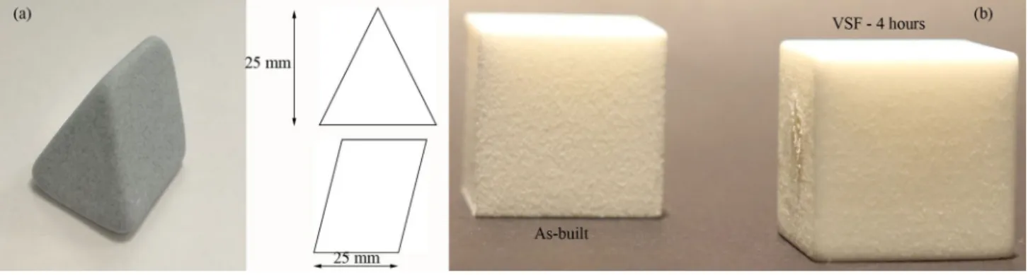
for the up-skin and down-skin parameters were 2500 and 2800 mm/s, respectively, while the other parameters were similar to the one used for the core region. In this study, two different models (cubical and horizontally built ten-sion test specimens) were selected for the surface treat-ment investigation in the VSF machine, Fig. 1.
After the samples’ fabrication in the SLS machine, the samples were exposed to different VSF machine times. The operation’s duration plays a significant role in attain-ing the desired surface qualities; therefore, four differ-ent time-based VSF parameters were chosen to treat the cubic samples. For each case, three cubic samples were prepared. In the tension test analysis, only one parameter of 4 h of the VSF process was used to compare the tension test results with the as-built condition. The tensile proper-ties of the as-built and VSF treated PA2200 samples were measured on the ALSA 100KN universal testing machine at a 2 mm/min test speed and a 50 KN load cell. Quasi-static tensile tests on materials were performed on ISO 527-2 [13], and five specimens were produced for each case. Mechanical testing of both the as-built and VSF treated SLS samples was carried out at room conditions of 23 °C/50% relative humidity within 48 h of production following ISO 291. Table 1 indicates the sample’s label based on the VSF machine’s duration and the sample type. In the VSF
Fig. 1 Schematic representation of the (a) cubic and (b) the tensile specimen
Table 1 Name-codes for the samples tried for different hours of VSF treatment
Name-codes Time (h) Cubical Tension test
As-built 0 ✓ ✓
H1 1 ✓ –
H2 2 ✓ –
H3 3 ✓ –
process, all the samples’ faces can be treated simultane-ously, which results in complete surface treatment without any personal intervention.
The surface roughness was measured using a Key-ence VHX-6000 digital microscope, and the param-eters Sa and Sz were used to characterize the surface quality. Sa is the average of the absolute value of all peaks and valleys to the median plane. Sz represents the sum of the largest peak height and the pit depth values within the specified area [14]. An average of 4 measurements was obtained on the plane parallel to the scanning direction at different as-built locations and the VSF treated samples. The surface roughness (Ra) measurements of the plane perpendicular to the scan-ning direction were slightly higher than the plane paral-lel to the scanning direction. After the VSF treatment, the surface roughness of the two orthogonal planes was found identical; therefore, the rest of the analysis was carried out only on the scanning plane. The hard-ness values were measured on the ASTM E384 certified standard microhardness tester from the Future-Tech FM310e. For better accuracy, an average hardness value was obtained from at least 3–6 measurements at differ-ent locations. The microstructure investigation of the as-built and the VSF treated samples was performed on the optical microscope (OM) from the Zeiss Axio lab and scanning electron microscope (SEM) from the Hitachi SU3500. The 3D surface topographic images of the samples were also taken using VHX 6000 series digital microscope KEYENCE to evaluate the impact of the VSF process’s duration on the surface texture of the PA2200 SLS samples.
The Vibratory surface finishing process was realized on the ETP-100 ERBA VSF machine having a 0.55 KW driving power and 1400 rpm. VSF machines are used for deburring, polishing, and roughness removal for both metals and non-metals. In the VSF process, spe-cially shaped media pellets and work-pieces are placed
together inside a vibratory tumbler. The tumbler’s vibra-tory action causes the media pellets to rub against the work-pieces, resulting in a smooth surface and slightly higher surface hardness than the bulk. The force and frequency of impact are much higher in dry impact con-ditions than in water-wet concon-ditions [15]. In the pre-sent study, the SLS samples post-processing in the VSF tumbler was realized without any lubrication. The media pellets used in this study were ceramic abrasive of size 25 × 25 mm, Fig. 2a. A direct view of the SLS cubical sam-ple, H4, clearly establishes the VSF process’s effect on the surface of the as-built component, Fig. 2b.
3 Results
3.1 Microstructure
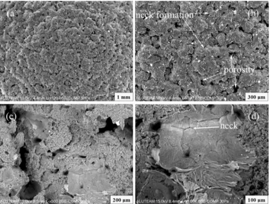
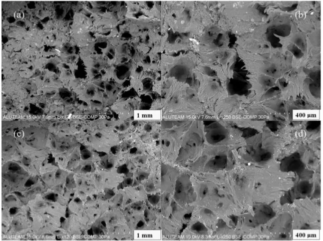
The microstructure of the top of the sample’s surface in the SEM micrograph represents the sintering of the powder particles where the fusion process is dominated by the neck formation, Fig. 3. This depicts that the particle’s inner zone remains largely unfused and that the outer region mainly experienced melting and recrystallization. This happens due to the insufficient energy density that fails to melt the powder particles completely to form a dense structure [16]. As a result, only the outer surfaces of the adjoining powder particles melt and fuse to form a neck. The unfused inner core region can be readily discernible from the general microstructure, as seen in Fig. 3d. This phenomenon also gives rise to a large number of pores formation appearing either individually or interconnected to form a large pore structure, as shown in the cutout sec-tion of the as-built SLS cubic sample in Fig. 3c. Some of these pores are relatively deeper that encompass sev-eral sintered layers, and the pores mainly appeared next to the particle edge. At the edge of the specimen, some extra powder particles can be seen attached to the main
Fig. 2 Shape and size of the cement granule used in the VSF process. A direct visual image of the effect of the VSF process of b 4 h on the a as-built SLS PA2200 cubic samples
component due to the partial fusion, which is difficult to distinguish from the given microstructure due to similar sintering phenomena. Partially attached powders are responsible for high surface roughness.
VSF is a surface treatment process that affects the tiny layers near the surface of the finished parts. The VSF pro-cess is a frequently used mass finishing operation that is mainly applied to alter the surface quality and impart the necessary compressive stresses on the components’ sur-faces [17]. Since the high tensile residual stresses in the top layers of the SLS components can facilitate the crack nucleation and its growth, the VSF process can fix it and enhance the overall performance of the SLS components [18, 19]. The effect of the VSF process and its duration on the surface texture of the as-built SLS samples can be seen in Fig. 4. As observed, any exposure (1, 2, 3, or 4 h) to the VSF process is likely to bring a significant change in the macrostructure of the SLS prepared polyamide PA2200 samples. After 1 h of the VSF operation, the typical micro-structure of the as-built SLS sample can be seen trans-forming into a combination of plastically deformed and material-removal feature-specific structures. It is because of the diverse interaction of the VSF media pellets with the surface of the sample. In the VSF process, the particle–sur-face interaction can be a mix of normal and transversal impacts where the normal impact is responsible for the
necessary surface depression, and the transversal impact results in material erosion [20].
According to [15], the particle–surface interaction in the VSF process can be assumed in three modes. First is the free-fall impact of the media pellet with the workpiece surface, resulting in a single crater and a smaller magni-tude of the force. In the present case, the free-fall impact can be hypothesized from a very short distance from the workpiece surface due to a significantly large density of media pellets in the tumbler. Since the workpiece is freely moving in the tumbler, the free-fall impact of the interact-ing media pellets can occur at different angles, resultinteract-ing in both normal and tangential free-fall impact. The normal impact can plastically deform the surface, whereas the tan-gential impact can result in material erosion. The second impact occurs due to the media pellets rolling onto the workpiece surface, resulting in a mixture of normal and tangential impact. This rolling form of impact can create many small craters and multiple distinct peaks of small impact force. Depending on the inclination of the work-piece surface, the magnitude of the normal and transver-sal impact may vary. This stage can produce more craters than the first stage at a relatively lower impact force. The third form of impact assumes the interacting media pellet to be stationary on the workpiece surface, which is repeat-edly hammered by the other surrounding media pellets
Fig. 3 The SEM micrographs of the a as-built SLS sample, b its magnified form, c interconnected porosity in the cut-out section, and d neck forming
either by rolling or free-falling over it. The third form of impact forms a single large crater with an impact force lasting longer than the other two modes. This third mode can be expected to be more common in the VSF process. Due to the large numbers of the media pellets in the tum-bler in the dry working conditions, the stationary media pellet can be assumed to remain motionless on a slightly inclined workpiece surface. As a result, the maximum ero-sion of the attached powder particles can occur at this stage, resulting in a significant breaking of attached pow-der particles and pore filling. As a result of the particle–sur-face interaction, five different features were observed in the microstructure of the H1 sample such as the original pores (A), pores left due to the incomplete powder filling (B), filled up pores (C), striation marks of the media pellets (D), and the stretched marks of the plastically deformed/ eroded powder particles (E), as shown in Fig. 4b. Thus, the circular morphology of the powder particles of the as-built SLS sample disappeared after the 1-h exposure in the VSF process. Moreover, several randomly-oriented stretch marks can be seen in Fig. 4. This is because of the plastic erosion of the partially-attached powder particles.
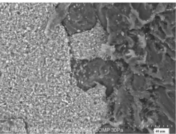
In addition to the above, the highly porous structure of the as-built SLS surface can be seen transforming into a relatively dense surface structure. The pores can be seen as fewer in numbers and smaller in size compared to the as-built state. Moreover, we hypothesized that some of the pores were filled with fine pieces of the powder parti-cles attached to the surface, most likely the ones close to the pores. This may be due to the breaking of the nearby attached powder particles during the direct impact by the VSF media pellets and later filling and welding of the pow-der’s fragments in the nearby pore due to the shearing effect during the transversal motion of the media pellets, as shown in Fig. 5. Some of these filled pores can be seen partly open, maybe due to the fallout of powder fragments during the media pellet-material interaction. The breaking and filling of powder particles can be imagined to occur while the samples were slightly inclined to the horizon-tal position (third mode of impact) since the size of the crater and the frequency of the impact force are higher than the other two modes of particle–surface interaction. The microstructure of the filled regions can be seen as dif-ferent from the main texture. However, it is unlikely that the filled regions would contribute to the strength of the
polyamide samples. This is because the filled regions were loosely bonded to the matrix, as observed in Fig. 5. Moreo-ver, the surface finishing process like VSF can only affect the few tiny layers near the sample’s surface [21]; therefore, the filling process can be limited to only small pores and restricted to the nearby sub-surface region only, resulting in weak bonding. The primary strength of the sample can, therefore, be assumed to come from the plastic deforma-tion of the surface.
As the duration of the VSF process increases, the sam-ples’ surface was found much smoother with less plasti-cally-deformed stretched marks and less pore density. The reduction in stretch marks is due to their further suppres-sion or erosuppres-sion by the media pellets, as observed in the cases of H2, H3, and H4 samples. Moreover, the striation marks in sample H1 can be seen in multiple directions due to random particle–surface interaction. The striation marks visibility reduces with the increased duration of the VSF process, resulting in a significantly lower density of striation marks and relatively much smoother texture, as observed in sample H4 of Fig. 6. Compared to the as-built state where significantly large deviations in a surface pro-file can be seen in combination with high porosity near the edge of the specimen, the VSF treated samples were found smoother with a complete absence of large pores in the sub-surface region, Fig. 6. The edge of the sample after the VSF process can be seen smoother and round in profile, with the surface representing more like a plasti-cally deformed structure. In cases of metals subjected to the shot-peening or vibratory surface finishing operation, it is already confirmed that the surface treatments alter the grain morphology of the surface and the sub-surface region of the SLM built components [22, 23]. Therefore, in the present case, the grains on the surface and within the sub-surface region can be assumed to be refined after the VSF operation. This results in a strong protective layer all around the sample. The effect of prolonged exposure of 4 h of VSF treatment results in the complete elimination of deviations from the surface of sample H4 compared to the sample H1, which still shows some rough ridges, as shown in Fig. 6b and c.
3.2 Surface roughness
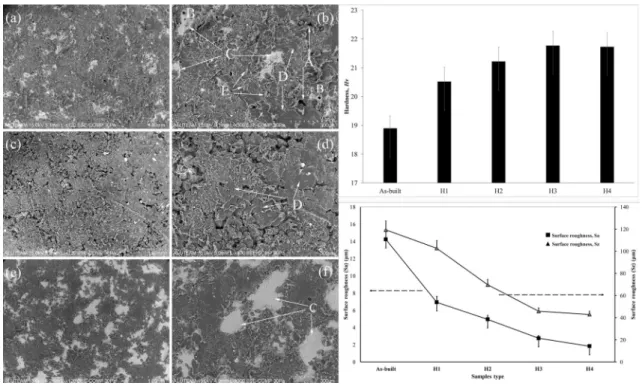
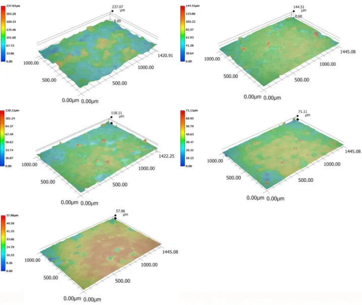
The surface roughness values of the as-built and the VSF treated SLS PA2200 samples are shown in Fig. 7. The high surface roughness of the as-built SLS sample is because of the deviations from the mean average size. The deviations mainly arise due to the semi-attached powder particles and high surface porosity. The average surface rough-ness of the as-built SLS PA2200 was found in a range of 13–16 µm on either plane, which is relatively high com-pared to any samples treated with the VSF process, as
Fig. 4 A characteristic SEM micrograph of the SLS PA2200 cubic samples a, b H1, c, d H2, e, f H3, and g, h H4. Here, the symbols A, B, C, D, and E represent the original pores, small pores left after the filling of the broken powders, pores filling phenomenon, media pellets striation marks, and the stretched marks of the plastically deformed/eroded powder particles during the VSF process, respec-tively. (NOTE: Figures b, d, f, and h are the magnified images of fig-ures a, c, e, and g, respectively)
observed from Fig. 7. The long duration of exposure in the VSF process to produce a reasonable change in the surface roughness values is due to the media pellets’ low impact force with the work-piece surface, resulting in less material erosion. The decrease of Sz indicates that the VSF process and the process duration were effective in subdu-ing peaks. Moreover, the decrease of Sa indicated a sur-face smoothening by the VSF process. Compared to the as-built state, even 1 h exposure in the VSF machine was reasonably successful in reducing the roughness by half. As the time to exposure increases, the surface roughness of the SLS sample was found further reducing by almost the same degree (> 40%) until sample H3. Finally, the sur-face roughness of the sample H3 and H4 was measured at 2.75 µm and 1.8 µm, respectively.
The three-dimensional surface topography of the as-built and VSF treated SLS PA2200 samples along the plane parallel to the scanning direction is shown in Fig. 8. The
Fig. 5 Filling of original pores of the as-built SLS samples by broken powder particles after the VSF process
images clearly establish the high waviness in the focus region of the as-built sample, which was found to reduce after the VSF treatment. The deviations from the mean average size were observed all across the surface, which is evident from the inconsistency in the laser sintering pro-cess. The surface topography in the H4 sample was found a lot smoother than the other cases with fewer deviations.
3.3 Hardness
The hardness measurements were made on both scanning and building planes of all the test samples, which were relatively similar in each case. Compared to the as-build state, the hardness values in samples after the VSF treat-ment was found to increase, however, less significantly, as observed in Fig. 9. The increase in hardness values in the VSF treated samples is attributed to the plastically deformed surfaces. As seen from Fig. 3, there exists a high pore density in the as-built SLS sample, and it was equally higher near the surface. After the VSF treatment, the SEM images showed a relatively smooth surface profile with less pore density. During the particle–surface interaction between the SLS sample’s surface and the hard ceramic abrasives, two different phenomena were observed that could have contributed to the high hardness of the SLS sample. First, the pore-filling by the broken fragments of the powder particles, and the second was the plastic deformation of the surface by the hard abrasive ceramic media pellets. As discussed before, the pore-filled struc-tures were loosely bonded to the matrix, and the VSF effect was only limited to the near sub-surface region; thus, the pore filling is unlikely to contribute to the high hardness of the SLS samples. On the other hand, the severe plastic
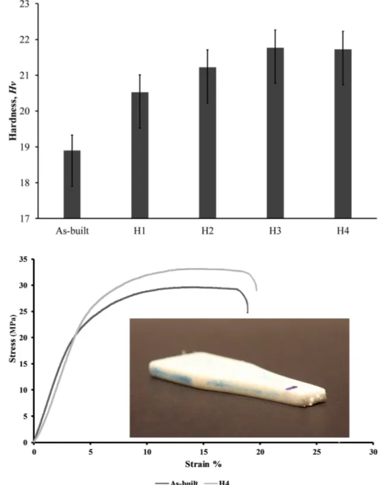
deformation of the surface can induce significant sur-face hardening, resulting in high hardness values in the SLS samples after the VSF treatment. As a result, the SLS samples’ hardness after VSF treatment was found slightly improving from 19 Hv to within a range of 21–22 Hv, as shown in Fig. 9.
3.4 Tension test results
The tension test results of the as-built and the H4 tension test specimens were conducted at room temperature. The tensile stress–strain curves of the two samples are shown in Fig. 10. The changes in the tensile strength, yield strength, and elongation at break are also presented in .
Table 2 as observed, the SLS sample after the VSF treat-ment exhibits slightly better mechanical properties com-pared to the as-built SLS equivalent. The VSF treatment results in forming a protective layer of refined grain struc-ture on the surface and within the sub-surface region of the H4 sample. According to the semi-empirical Hall–Petch (HP) equation [24], the proof stress of the component is directly proportional to the square root of the grain size. Therefore, the strength of the surface of the H4 sample improves considerably, although the bulk region remains ineffective in the VSF process. As known before, the crack generally nucleates from the surface of the component; therefore, the surface enhancement can practically delay the crack formation, thereby increasing the strength and the life of the component.
The fracture surfaces of the as-built and the H4 sam-ples are shown in Fig. 11. The micrographs established that the failure in the two specimens was of the ductile mode
Fig. 7 The effect of the VSF process’s duration on the surface roughness of the SLS PA2200 samples
(inset of Fig. 10). The two samples were observed with lit-tle lateral contraction (necking), and the fracture surface was characterized by ductile dimpling. However, it was difficult to distinguish the amount of plastic deformation in the two specimens, which shows similar behavior. The mechanical strength, as well as the elongation at break, was found slightly better in the H4 sample compared to the as-built case.
4 Discussion
The SLS process enables the neck formation and growth of the individual powder particles via surface tension to produce a three-dimensional solid structure [16]. The high surface roughness of the order of 13 – 16 μm was observed mainly due to the partially attached powder particles near
the surface of the as-built SLS PA2200 components. The high surface porosity in SLS structures may act as stress raisers, significantly affecting the structural performance during service life. High surface irregularities and sub-surface porosities due to the non-uniform sub-surface mor-phology are sensitive regions for crack nucleation [25]. The components’ exposure to VSF treatment resulted in a significant drop in the surface roughness values. The kinetic energy of the impacting VSF media eliminates the protruding un-molten powder particles and surface agglomerates, reducing the surface roughness by 90% after 4 h of VSF operation. The particle–surface interaction in the VSF process can be a mixture of media pellet free-fall and rolling on the workpiece surface or the media pellet resting on the workpiece surface. This interaction results in the normal and tangential impact of the media pellet on the samples’ surface, causing its material removal and
work-hardening. As a result, the highly porous structure transformed into a relatively dense surface structure with fewer pores.
Moreover, VSF surface treatment also induces consider-able compressive residual stress and work-hardening on the material surface by refining the surface morphology [26]. The hardness study revealed a slight improvement in the surface hardness by 15% due to the plastic defor-mation caused by the repetitive media-pellet impacts on the work-piece surface. The plastic deformation induces compressive residual stress in the sub-surface region and the modification of the surface microstructure in the form of grain refinement, resulting in surface hardness improve-ment in the mechanically treated components [27]. There-fore, surface hardening using mechanical post-processing
Fig. 9 The effect of the VSF durations on the surface hard-ness of the as-built SLS PA2200 cubic samples
Fig. 10 The stress–strain curves of the as-built SLS sample and after 4 h of VSF operation
Table 2 Mechanical properties from the stress–strain curve Sample Yield strength
(MPa) (± SD) Tensile strength (MPa) (± SD) Elongation at break (% EL) (± SD) As-built 18.12 (1.87) 29.6 (2.36) 18.1 (1.58)
methods is ideal for producing necessary compressive residual stress by modifying surface layer microstructure.
As the duration of the VSF process increases, the sam-ples’ surface was found much smoother with less plasti-cally-deformed stretched marks and less pore density. Higher kinetic energy due to the VSF treatment resulted in wider plastic indentations compared to the as-built case. The indentations were even more accentuated at a longer VSF treatment duration due to the higher deform-ability and surface hardening. In general, regardless of the VSF process duration, the surface-treated specimens represented a more regular surface morphology than the as-built series. The SLS specimens without VSF treatment exhibited slightly lower mechanical strength, signifying easy crack nucleation due to the high surface roughness leading to a lower mechanical strength. On the other hand, the VSF process led to comparably higher mechani-cal strengths due to the reduced surface roughness with homogeneous surface morphology and high compressive residual stresses in the sub-surface region.
5 Conclusion
It is well understood that the high surface roughness and sub-surface porosity of the additive components are det-rimental to their mechanical strength. The highly tran-sient processing conditions limit the SLS components’ practical usage in several critical applications. Moreover, any further optimization of the SLS processing param-eters is considered insufficient in bringing the necessary change in the overall mechanical and microstructural features of the additive components. This work evalu-ated the effect of the vibratory surface finishing process on the mechanical and physical properties of PA2200 parts fabricated by the SLS process. The VSF treated SLS samples achieved overall better mechanical strength and reduced surface roughness than the as-built series. An increase in the VSF process duration showed drastic improvement in surface roughness values with moder-ate changes in surface hardness, UTS, and ductility. The reduction in surface roughness and hardness of the SLS samples after 3 or 4 h of VSF duration was nearly 90% and 15%, respectively, indicating higher toughness
achievement at longer particle–surface interaction duration. The post-processing surface treatments like the VSF process demonstrate the potential to improve the overall mechanical and microstructural features of AM parts by altering their surface layer microstructure. The VSF media-pellets achieve this by plastically deform-ing the work-piece surface and inducdeform-ing compressive residual stresses and work-hardening in the surface layer. Future work will need to monitor the combined effect of the thermal and mechanical-based post-processing treatments of the SLS parts and characterize their micro-structures to assess the effect of density, surface rough-ness, hardrough-ness, and crystallite sizes on the mechanical properties of the SLS PA2200 parts.
Compliance with ethical standards
Conflicts of interest The authors declare that they have no conflict of interest.
Open Access This article is licensed under a Creative Commons Attri-bution 4.0 International License, which permits use, sharing, adap-tation, distribution and reproduction in any medium or format, as long as you give appropriate credit to the original author(s) and the source, provide a link to the Creative Commons licence, and indicate if changes were made. The images or other third party material in this article are included in the article’s Creative Commons licence, unless indicated otherwise in a credit line to the material. If material is not included in the article’s Creative Commons licence and your intended use is not permitted by statutory regulation or exceeds the permitted use, you will need to obtain permission directly from the copyright holder. To view a copy of this licence, visit http://creat iveco mmons .org/licen ses/by/4.0/.
References
1. Salmoria GV, Leite JL, Ahrens CH, Lago A, Pires ATN (2007) Rapid manufacturing of PA/HDPE blend specimens by selective laser sintering: Microstructural characterization. Polym Test 26:361– 368. https ://doi.org/10.1016/j.polym ertes ting.2006.12.002
2. Zarringhalam H, Hopkinson N, Kamperman NF, de Vlieger JJ (2006) Effects of processing on microstructure and properties of SLS Nylon 12. Mater Sci Eng A 435–436:172–180. https ://doi. org/10.1016/j.msea.2006.07.084
3. Nussbaum J, Kaur T, Harmon J, Crane NB (2021) Impact of sinter-ing time and temperature on mechanical properties in projec-tion sintering of Polyamide-12. Addit Manuf 37:101652. https :// doi.org/10.1016/j.addma .2020.10165 2
4. Eosoly S, Vrana NE, Lohfeld S, Hindie M, Looney L (2012) Inter-action of cell culture with composition effects on the mechani-cal properties of polycaprolactone-hydroxyapatite scaffolds fabricated via selective laser sintering (SLS). Mater Sci Eng C 32:2250–2257
5. Özbay B, Serhatlı E (2020) Processing and characterization of hollow glass-filled Polyamide 12 composites by selective laser sintering method. Mater Technol 00:1–11. https ://doi. org/10.1080/10667 857.2020.18241 49
6. Tong Q, Xue K, Wang T, Yao S (2020) Laser sintering and invalidat-ing composite scan for improvinvalidat-ing tensile strength and accuracy of SLS parts. J Manuf Process 56:1–11
7. Van Hooreweder B, De Coninck F, Moens D, Boonen R, Sas P (2010) Microstructural characterization of SLS-PA12 speci-mens under dynamic tension/compression excitation. Polym Test 29:319–326. https ://doi.org/10.1016/j.polym ertes ting.2009.12.006
8. Mahmood KH, Yusuf K, Ozhan K, Yusuf K, Jawahir IS (2020) Influ-ence of the post-processing operations on surface integrity of metal components produced by laser powder bed fusion addi-tive manufacturing : a review. Mach Sci Technol, pp 1–43. https ://doi.org/10.1080/10910 344.2020.18556 49
9. Bagherifard S, Beretta N, Monti S, Riccio M, Bandini M, Guagli-ano M (2018) On the fatigue strength enhancement of additive manufactured AlSi10Mg parts by mechanical and thermal post-processing. Mater Des 145:28–41. https ://doi.org/10.1016/j. matde s.2018.02.055
10. Bagherifard S, Slawik S, Fernández-Pariente I, Pauly C, Mücklich F, Guagliano M (2016) Nanoscale surface modification of AISI 316L stainless steel by severe shot peening. Mater Des 102:68–77.
https ://doi.org/10.1016/j.matde s.2016.03.162
11. Tian YB, Zhong ZW, Tan SJ (2016) Kinematic analysis and experimental investigation on vibratory finishing. Int J Adv Manuf Technol 86:3113–3121. https ://doi.org/10.1007/s0017 0-016-8378-x
12. Uhlmann E, Dethlefs A, Eulitz A (2014) Investigation into a geom-etry-based model for surface roughness prediction in vibratory finishing processes. Int J Adv Manuf Technol 75:815–823. https ://doi.org/10.1007/s0017 0-014-6194-8
13. ISO B (1997) Plastics–determination of tensile properties 14. Scherillo F (2019) Chemical surface finishing of AlSi10Mg
com-ponents made by additive manufacturing. Manuf Lett 19:5–9.
https ://doi.org/10.1016/j.mfgle t.2018.12.002
15. Yabuki A, Baghbanan MR, Spelt JK (2002) Contact forces and mechanisms in a vibratory finisher. Wear 252:635–643. https :// doi.org/10.1016/S0043 -1648(02)00016 -9
16. Cai C, Tey WS, Chen J, Zhu W, Liu X, Liu T, Zhao L, Zhou K (2021) Comparative study on 3D printing of polyamide 12 by selec-tive laser sintering and multi jet fusion. J Mater Process Technol 288:116882
17. Zhang J, Alcaraz JY, Yeo S-H, Nagalingam AP, Gopinath A (2021) Random impact FEM simulation of irregularly-shaped media for parametric study of vibratory surface enhancement. Proc Inst Mech Eng Part B J Eng Manuf. 0954405421990128. https ://doi. org/10.1177/09544 05421 99012 8
18. Kaynak Y, Tascioglu E (2020) Post-processing effects on the sur-face characteristics of Inconel 718 alloy fabricated by selective laser melting additive manufacturing. Prog Addit Manuf 5:221– 234. https ://doi.org/10.1007/s4096 4-019-00099 -1
19. Kaynak Y, Kitay O (2019) The effect of post-processing opera-tions on surface characteristics of 316L stainless steel produced by selective laser melting. Addit Manuf 26:84–93. https ://doi. org/10.1016/j.addma .2018.12.021
20. Hashimoto F, DeBra DB (1996) Modelling and optimization of vibratory finishing process. CIRP Ann 45(1):303–306. https ://doi. org/10.1016/S0007 -8506(07)63068 -6
21. Khan HM, Özer G, Tarakci G, Coskun M, Koc E, Kaynak Y (2021) The impact of aging and drag-finishing on the surface integrity and corrosion behavior of the selective laser melted marag-ing steel samples. Materwiss Werksttech 52:60–73. https ://doi. org/10.1002/mawe.20200 0139
22. Uzan NE, Shneck R, Yeheskel O, Frage N (2018) High-temper-ature mechanical properties of AlSi10Mg specimens fabri-cated by additive manufacturing using selective laser melting
technologies (AM-SLM). Addit Manuf 24:257–263. https ://doi. org/10.1016/j.addma .2018.09.033
23. Bernhardt A, Schneider J, Schroeder A, Papadopoulous K, Lopez E, Brückner F, Botzenhart U (2021) Surface conditioning of additively manufactured titanium implants and its influence on materials properties and in vitro biocompatibility. Mater Sci Eng C 119:111631. https ://doi.org/10.1016/j.msec.2020.11163 1
24. Suryanarayana C, Norton MG (1998) A practical approach. Ple-num Press, New York
25. Mavoori NK, Vekatesh S, M MH (2019) Investigation on surface roughness of sintered PA2200 prototypes using
Taguchi method. Rapid Prototyp J 25(3):454–461. https ://doi. org/10.1108/RPJ-10-2017-0201
26. Khangarot H, Kumar V, Sharma R, Maurya A, Hira J (2021) Modal analysis of vibratory finishing machine using ANSYS Software BT—avances in systems engineering. In: Misra RK (ed) Saran VH. Springer, Singapore, pp 447–456
27. Guo J, Bai J, Liu K, Wei J (2018) Surface quality improvement of selective laser sintered polyamide 12 by precision grinding and magnetic field-assisted finishing. Mater Des 138:39–45 Publisher’s Note Springer Nature remains neutral with regard to jurisdictional claims in published maps and institutional affiliations.