SN Applied Sciences (2019) 1:415 | https://doi.org/10.1007/s42452-019-0446-z
Single‑needle electrospinning of PVA hollow nanofibers for core–shell
structures
Yusuf Kaan Doğan1 · Alparslan Demirural1 · Tarık Baykara1 © Springer Nature Switzerland AG 2019
Abstract
As one of the most promising nanostructures, core-/shell-structured nanofiber has been widely used in many applications such as self-healing, drug and gene delivery, and tissue engineering. Hollow or core-/shell-structured nanofibers have generally been produced using single-needle and/or coaxial electrospinning methods. This method involves occurrence of varying sizes of bead formation. In this study, a single-needle electrospinning technique is applied for investigating the processing parameters affecting the fiber morphology and the bead formation in order to understand this innova-tive technique for further studies. Results showed that the parameters such as the voltage difference, collector distance and solution concentration have significant effects on the shell fiber morphology and the occurrence of bead formation. Keywords Electrospinning · Hollow nanofibers · Core/shell structure · Nanofibers · Self-healing · Bead formation
1 Introduction
The electrospinning has been attracting considerable attention as an effective method for developing multi-functional micro- and nanofibrous materials from various polymers and composites [1–4]. Micro- and nanofibers produced using the electrospinning technique have many extraordinary properties such as high surface-to-volume ratio, high porosity, extremely small diameters along with interconnected micro-/nanostructure and surface func-tionality. Recently, they have been widely utilized and used in a variety of applications such as biomedical [5, 6], tissue engineering [7], drug delivery [1, 8], wound heal-ing, sensors, smart textiles, composite reinforcements [9], filtration [10] and self-healing [11]. One of the most demanding areas for nanofibers is in biomedical stud-ies. Nanofibers are proved to be the perfect candidates for drug delivery and tissue applications [6]. For example, nanofiber mats can be used for providing a platform for tissue cells; therefore, tissue cells can multiply and differ-entiate for the tissue that they meant to form [7]. Kalantari et al. [12] explained how chitosan nanofibers are used for
tissue scaffolds, wound dressings and antibacterial coat-ings. Moreover, Ghosal et al. [13] reviewed the utilization of polymer–titanium dioxide nanocomposites for tissue engineering and wound dressing and discussed the sig-nificance of the electrospinning technique in these appli-cations. Recently, functional composite nanofibers have been loaded with β-TCP and SIM, which are manufactured by electrospinning method are studied for drug delivery system by Rezk et al. In all these applications and many others [2, 4, 14–16], electrospinning is adopted due to ease of production and straightforward setup.
The electrospinning method can be regarded as a very flexible, simple and versatile technique that has varieties as follows: single-needle electrospinning, coaxial ning, modified coaxial electrospinning, blend electrospin-ning and side-by-side electrospinelectrospin-ning [1]. Among these, “the coaxial electrospinning” is the technique to produce such structures in which two or more dissimilar solutions injected independently from two different coaxial capillary channels. Coaxially spun hollow and core-/shell-structured nanofibers have been attracting considerable attention in recent years [17–20] and shown to be very promising in
Received: 30 January 2019 / Accepted: 2 April 2019 / Published online: 5 April 2019
self-healing, drug and gene delivery and tissue engineer-ing [12–17, 21]. Mainly, core-/shell-structured nanofibers which could also be considered as composite nanofibers constitute two parts, namely the inner “core” and the outer “shell” layer [17, 22]. Both layers can be utilized for differ-ent purposes and functions with differing compositions. In this technique, the voltage difference between needle and collector is used to create an electrical area that affects the droplet formation at the tip of the needle and draws nanofibers from the tip to the collector [4]. The most prom-ising approach for producing core-/shell-structured fibers involves the use of coaxial needles.
In this regard, it is possible to combine a variety of com-positions to create original and innovative applications in so many different fields [23]. As an interesting example in this respect, bovine serum albumin (BSA)-containing dextran is embedded in polycaprolactone (PCL) nanofib-ers for drug delivery applications [24]. For the purpose of drug or gene carrier, polyelectrolyte complexes (PECs) are produced by mixing two polymers with opposing charges that form a two-component complex on a molecular level [23]. Self-healing is a significant field in smart and auton-omous materials attracting considerable attention both commercially and scientifically [9, 11]. One example of the self-healing technique is where the micro-/nanoen-capsulated healing agent is released upon cracking into the epoxy matrix and reacts with the catalysts to repair the damaged sites [9]. In a recent study, it is shown that self-healing of scratch and/or cracks can be healed using polystyrene (PS) fibers with core shell structure fabricated by coaxial electrospinning technique. In this, epoxy or cur-ing agent as healant loaded as the core and PS as the shell are shown to an effective self-healing system which heals a scratch on a coating surface [24].
Bead formation occurs in the electrospinning of nanofibers, and they may function as nanopockets acting as reservoirs for the healing agents. In this regard, liquid healing agents encapsulated in beads may have a critical role in self-healing mechanism. There are certain process-ing factors affectprocess-ing the formation and manipulation of the size of beads [11, 25].
Due to the significance of this technique, it is obvious that conducting a study on the processing of the electro-spinning will shed light and develop a better understand-ing of the formation of beads. In this work, a sunderstand-ingle-needle electrospinning technique is studied and the processing parameters affecting the fiber morphology and bead formation such as solution concentration, voltage dif-ference and collector distance are investigated in order to understand the technique for further studies. Hollow nano- and near-nanosized fibers were manufactured and examined using SEM–scanning electron microscope–tech-niques. Processing parameters were studied along with
the morphological features of the hollow fibers and beads. Consequently, developing insight into processing param-eters effects via electrospinning method requires too many solution pairs in the experiment. In this regard, the results of the single-needle/nozzle experiments can be extrapolated for forecasting the results in coaxial applica-tions considering the solution pair’s features by research-ers conducting these experiments.
2 Materials and experimental methods
2.1 Materials and methodsPolyvinyl alcohol (PVA) is selected as the electrospinning polymer owing to its cheaper price and the availability of its solvent which is distilled water. Polyvinyl alcohol (PVA,
Mw = 85,000–124,000) is purchased from Sigma-Aldrich and used without further purification.
2.1.1 PVA solution preparation
PVA is dissolved using distilled water in an Erlenmeyer flask and stirred with a magnetic stirrer at 40–45 °C for 2.5 h. Then the solution is filtered via filter paper to avoid the formation of dust and unwanted particles which may affect the fiber morphology. 10, 12 and 15 wt% PVA solu-tion concentrasolu-tions were used in electrospinning trials. 2.1.2 Electrospinning process
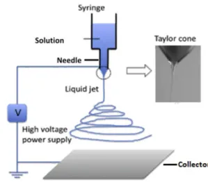
The method is widely used by other researchers and refers to early 1900s Formhals’ patents [26, 27]. Modern electro-spinning setups consist of pumps, syringes, high-voltage power supply, needle, camera and collector as shown in Fig. 1. The metal needle is connected to the positive pole of the power supply, and the collector is connected to the negative one. The high voltage difference between needle and collector creates an electrically charged solution at the tip of the needle.
The charged solution forms a phenomenon called “Tay-lor cone” and polymer jets start to be drawn out from the tip of the needle to the collector, while the pump feeds the needle tip with the solution through the syringe. Sol-vents are vaporized during flight; thus, jet solidifies before reaching to the collector. There are several parameters that affect the morphology of the fibers. The size of the volt-age difference affects the diameter and dispersion of the fibers on the collector. A collector may be a rotating disk, rotating drum or a simple aluminum plate as in this work. Parameters affecting the electrospinning technique can be listed as follows: ambient parameters, solution param-eters and application paramparam-eters. Ambient paramparam-eters
consist of humidity and temperature. Solution parameters are solution concentration and surface tension. Process-ing conditions are voltage difference, collector distance, collector rpm and flow rate [1]. In this work, processing conditions and solution concentration were investigated. 2.1.2.1 Electrospinning experiments A series of experi-ments were carried out to investigate the effect of solu-tion concentrasolu-tion, voltage difference and collector dis-tance. All experiments were conducted between 24 and 26 °C and 44 and 50% relative humidity. Selected solution concentration varied from 10 to 15 wt%. Voltage differ-ence varied between 15 and 30 kV. Collector distance var-ied between 10 and 19 cm. A small jack is implemented into the electrospinning chamber in order to control the collector distance. An aluminum collector plate, which is connected to the negative pole, is placed on top of the jack. Samples are collected on 10 cm × 10 cm aluminum foils that are placed on the aluminum plate. During the experiments, the flow rate varied between 0.1 and 0.5 mL/h. In the literature, it is possible to find various flow rates for the same conditions [27–31]. Liu et al. stated that flow rate does not hold a significant effect on fiber mor-phology considering the fact that the jet can accelerate to a velocity higher than velocity of sound in a very short time. Thus, in this work, it is accepted as an initial condi-tion and not inspected [25].
2.1.3 Microstructural investigation using scanning electron microscopy (SEM) techniques
It is very well known that the SEM uses an electron gun to make an electron bombardment on the samples and the interaction due to the bombardment of high-energy electrons reveals specific data/signals. The processor of the
device then generates the image of the sample. It is pos-sible to analyze the chemical composition of the sample as well [32]. For polymeric samples, however, the gold coat-ing process is needed; otherwise, high-energy bombard-ment burns the sample and becomes difficult to observe the morphology. Thus, a gold coating device is used, and samples were gold coated prior to utilization of the SEM. For characterization, JEOL JCM 6000 + desktop scanning electron microscope is used.
Samples were prepared by cutting a small piece of alu-minum sheets on the collector where the fibers are col-lected. They were taken from the regions with higher den-sity. Samples were gold coated for 2 min. Higher filament current resulted in images with better quality. 15 kV volt-age gave better imvolt-age quality; even though the samples were coated with gold, 15 kV voltage burnt the samples and caused electron etching in case of focusing a specific spot for more than 2 min, in 30,000 × magnification. There-fore, 10 kV voltage is used. Probe current was selected as standard. Measurements and characterization of nanofib-ers were conducted using the software in the SEM system; specifically, diameters of the nanofibers were measured and recorded using the precision indicator of the system.
3 Results and discussion
Three parameters affecting the bead formation were inves-tigated, these being the solution concentration, voltage difference and collector distance. It is reported that a bead distributed network of a nanofibrous structure is desired for self-healing, drug delivery and tissue engineering applications. Beads filled with drugs and/or self-healing agents act as reservoirs to repair/heal the damaged and/ or corroded sites of the structure [9, 25]. However, it should be noted that the occurrence of beads may not be benefi-cial and considered as a drawback for other purposes such as filtering, sensors, textiles and composite reinforcements.
3.1 Voltage difference
Negative and positive voltages effect both the formation and the dispersion of the nanofibers. Higher negative volt-ages resulted in a wide dispersion of fibers on the plate, causing longer electrospinning time for the desired den-sity in the characterization. Therefore, the negative voltage was set to − 2 kV. Experiments for the voltage difference are tabulated in Table 1 for 15 wt% solution concentration and 19 cm collector distance.
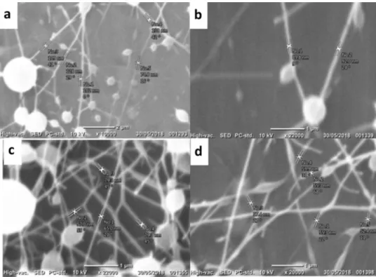
As it is clearly seen from SEM micrographs given in Fig. 2a–d, increasing voltage difference resulted in thin-ner fibers. For 15 kV, beads are spherical with a frequent distribution. Even though the fiber formation still exists,
the diameter difference is quite high between spherical beads and fibers. For 20 kV, beads are still spherical, yet less in quantity. When 25 kV is applied, the spherical beads tend to have an elliptical morphology. In the experiment with 30 kV, bead formation is observed to be smoother, closer to the fiber formation. This result shows that for fewer beads and more continuous fibers, a higher volt-age must be applied. This is due to higher charge density at the tip of the Taylor cone. Table 2 shows the results of electrospinning experiments on the fiber morphology for voltage difference effect with 15 wt% solution concentra-tion and 19 cm collector distance.
3.2 Collector distance
Collector distance from the tip of the needle is another parameter effecting the fiber morphology and bead for-mation. Closer the distance means stronger the electrical field effecting the solution jet [33]. Therefore, even for rel-atively lower voltage differences, solution jet is exposed
to a strong electrical field. Another kind of the effect is that the solvent has less time to evaporate in case of short distances. Hence, for very close distances such as 5 cm, there is no fiber formation on the collector because the jet never solidifies. On the other hand, very long distances cause the electrical field to be weaker since the poles are far away from each other; thus, thicker fiber morphology is expected [27]. In the experiment, a laboratory jack is used to adjust the collector distance to the desired value, as it is stated in Sect. 2.1.1.1. Very short distances may cause electrical arcs between needle and collector; accordingly, distances below 10 cm were not considered in this work. The voltage difference is selected to be 30 kV to create the thinnest fibers possible. Table 3 shows the experiments for different collector distances with a constant voltage difference of 30 kV and solution concentration of 15 wt%.
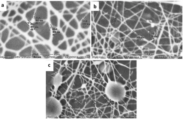
SEM micrographs given in Fig. 3a–c illustrate that the 10 cm distance resulted in thicker fibers with an average diameter of 229 nm. Although there are thinner fibers as
Table 1 Electrospinning
experiments for voltage difference for 15 wt% solution concentration and 19 cm collector distance Experiment # Voltage difference (kV) 1 15 2 20 3 25 4 30
Fig. 2 Fiber
micromorpholo-gies at voltage difference a 15 kV, b 20 kV, c 25 kV, d 30 kV
Table 2 Fiber morphology with the voltage difference
Experi-ments # Voltage differ-ence (kV) Avg. fiber diameter (nm) Bead morphology
1 15 110.36 Spherical
2 20 90.90 Spherical; lesser beads
3 25 70.15 Elliptical
4 30 56.06 More elliptical and
smoother; lesser beads
well in the sample, other collector distances did not per-form thicker fibers as the trial with 10 cm did. Thicker fib-ers occurred since the jet did not have enough time to solidify. However, beads did not occur. 15 cm distance per-formed thinner fibers without beads. This morphology is a desired morphology in general (see Table 4; Fig. 3a–c). Therefore, one can conclude that 15 cm distance is the most appropriate distance because in the 19 cm distance, even though the fibers are the thinner, large size bead for-mation occurred.
3.3 Solution concentration
Solution concentration is strongly associated with the viscosity of the solution because it increases the viscos-ity. Therefore, it holds a crucial role when it comes to the formation of the solution jet at the tip of the Taylor cone. It is expected that the solution with higher concentration
will form a thicker jet because drag forces exerted by the electrical area to the fluid cannot overcome the intermo-lecular bonding between fluid molecules. Table 5 shows the electrospinning experiments for solution concentra-tion effect with the voltage difference, 30 kV and the col-lector distance of 15 cm.
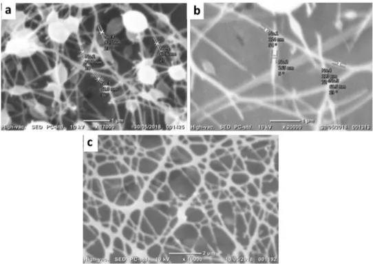
In Fig. 4a, there are many beads in the sample, even though the fibers have 88 nm of diameter on average.
Table 3 Electrospinning
experiments for collector distance effect, voltage difference 30 kV, solution concentration 15 wt% Experiments # Collector distance (cm) 1 10 2 15 3 19
Fig. 3 Fiber micromorphologies at collector distance a 10 cm, b 15 cm, c 19 cm
Table 4 Fiber morphology with varying collector distances: 10 cm,
15 cm, 19 cm Experiments
# Collector dis-tance (cm) Average fiber diam-eter (nm) Beads
1 10 229 No beads
2 15 146 No beads
3 19 104.5 Beads exist
Table 5 Electrospinning
experiments for solution concentration; voltage difference 30 kV; collector distance 15 cm Experiments # Solution concentration (wt%) 1 10 2 12 3 15
The beads are formed due to low surface tension and lower concentration. The force exerted on the solution jet due to high voltage difference can overcome the intermolecular bonds in the fluid if the viscosity is low. As shown in Fig. 4b, 12 wt% the solution resulted in a fewer number of beads. Consequently, in Fig. 4c, the continuous fibers demonstrated no beads. Measure-ments were taken on the continuous fibers which were not observed in other samples. Such a distinct effect of no beads and microspheres is also reported in a study with 15 wt% DCM (dichloromethane)/CE (2-chloroetha-nol) concentration. It was attributed to the surface ten-sion which minimizes the surface area [30]. Obviously, an increase in the surface tension is owed to an increase in the solution concentration and it results in very few or no bead formation. Table 6 shows the results of the dependence of fiber morphology and bead formation on the solution concentration.
4 Conclusion
This study investigated the formation of beads and nanofibers to gain a better understanding of the elec-trospinning process. Elecelec-trospinning parameters studied were voltage difference, collector distance and solution concentration. Results showed that these parameters have significant effects on the size and the number of beads, fiber morphology and the efficiency of the electrospin-ning process. It is demonstrated that the fiber diameter decreases as the voltage increases. This might be due to the possibility that stronger electrical forces and denser charge on the tip of the Taylor cone may decrease the diameter of the jet. Experiments for various collector distances revealed that fibers tend to form thinner and non-beaded morphology in a specific collector distance. (15 cm distance performed thinner fibers without beads.) Fiber diameter continues to decrease with the increasing distance, and bead formation starts to occur. The reason behind this might be the instability in the Taylor cone. Shorter distances than 15 cm result in thicker and non-beaded fibers. This can be ascribable to jet’s lack of solidi-fication in short distances. Thus, the jet gets flatten after it hits the plate. Moreover, very short distances such as 5 cm may even cause the solvents not to vaporize; hence, the fiber formation may not occur. About the solution concentration, it is found that increasing the concentra-tion of polymer soluconcentra-tion prevents bead formaconcentra-tion and results in continuous and thicker nanofiber morphology. The reason behind this can be the fact that intermolecular bonds are stronger in case of a higher viscosity which is
Fig. 4 Fiber
micromorpholo-gies at solution concentration
a 10 wt%, b 12 wt%, c 15 wt%
Table 6 Fiber morphology depending on solution concentration
Experi-ment # Solution concen-tration (wt%) Avg. fiber diameter (nm) Beads
1 10 88 Exist, spherical
2 12 115 Smoother beads
3 15 126 More continuous,
no beads on fibers
caused by the increase in solution concentration. In case of desiring to produce fibers with beads for specific pur-poses, one should try to increase the collector distance [11]. If straightly formed nanofiber formation is aimed as in the case for tissue scaffolds of Venugopal et al. [34] work, thicker solution concentration and closer collector distances with lower voltage should be utilized during the processing. The micro-/nanofiber diameter can be con-trolled using these parameters.
Acknowledgements The authors would like to thank the Istanbul
Development Agency for their support through the funding of the Project Nos. İSTKA TR10/15/YNK/056 and TR10/16/YNY/0016.
Compliance with ethical standards
Conflict of interest The authors declare that they have no conflict of
interest.
References
1. Zhang H, Niu Q, Wang N, Nie J, Ma G (2015) Thermo-sensitive drug controlled release PLA core/PNIPAM shell fibers fabricated using a combination of electrospinning and UV photo-polym-erization. Eur Polym J 71:440–450
2. Karakas H (2014) Electrospinning of nanofibers and their appli-cations. MDT Electrospinning 3:1–35
3. Fang J, Wang X, Lin T (2003) Functional applications of elec-trospun nanofibers. In: Nanofibers-production, properties and functional applications, Intechopen, London, pp 287–326 4. Bhardwaj N, Kundu SC (2010) Electrospinning: a fascinating fiber
fabrication technique. Biotechnol Adv 28(3):325–347
5. Elahi MF, Lu W (2013) Core-shell fibers for biomedical applica-tions—a review. J Bioenergy Biomed Sci 03(01):1–14
6. Leung V, Ko F (2011) Biomedical applications of nanofibers. Polym Adv Technol 22(3):350–365
7. Chae T, Ko F (2017) Electrospun nanofibrous tissue scaffolds. In: Electrospun nanofibers, Woodhead publishing series in textiles, pp 521–550
8. Jiang H, Hu Y, Zhao P, Li Y, Zhu K (2006) Modulation of protein release from biodegradable core-shell structured fibers pre-pared by coaxial electrospinning. J Biomed Mater Res Part B Appl Biomater 79(1):50–57
9. Yin T, Rong MZ, Zhang MQ, Yang GC (2007) Self-healing epoxy composites—preparation and effect of the healant consisting of microencapsulated epoxy and latent curing agent. Compos Sci Technol 67:201–212
10. Kosmider K, Scott J (2002) Polymeric nanofibre exhibit an enhanced air filtration performance. Filtr Sep 39(6):20–22 11. Park JH, Braun PV (2010) Coaxial electrospinning of self-healing
coatings. Adv Mater 22(4):496–499
12. Kalantari K, Afifi AM, Jahangirian H, Webster TJ (2018) Biomedi-cal applications of chitosan electrospun nanofibers as a green polymer—review. Carbohydr Polym. https ://doi.org/10.1016/j. carbp ol.2018.12.011
13. Ghosal K, Agatemor C, Špitálsky Z, Thomas S, Kny E (2018) Elec-trospinning tissue engineering and wound dressing scaffolds from polymer—titanium dioxide nanocomposites. Chem Eng J 1:1. https ://doi.org/10.1016/j.cej.2018.10.117
14. Huang ZM, Zhang YZ, Kotaki M, Ramakrishna S (2003) A review on polymer nanofibers by electrospinning and their applica-tions in nanocomposites. Compos Sci Technol 63(15):2223–2253
15. Khalf A, Madihally SV (2017) Modeling the permeability of multi-axial electrospun poly(ε-caprolactone)-gelatin hybrid fibers for controlled doxycycline release. Mater Sci Eng, C 76:161–170 16. Reneker DH, Yarin AL (2008) Electrospinning jets and polymer
nanofibers. Polymer (Guildf) 49(10):2387–2425
17. Fang J, Wang X, Lin T (2003) Functional applications of elec-trospun nanofibers. In: Nanofibers-production, properties and functional applications, IntechOpen, pp 287–326
18. Priya ARS, Subramania A, Jung YS, Kim KJ (2008) High-perfor-mance Quasi-solid-state dye-sensitized solar cell based on an electrospun PVdF-HFP membrane electrolyte. Langmuir 24(17):9816–9819
19. Wang ZL, Song J (2006) Piezoelectric nanogenerators based on zinc oxide nanowire arrays. Science 312(5771):242–246 20. Chang C, Tran VH, Wang J, Fuh YK, Lin L (2010) Direct-write
piezo-electric polymeric nanogenerator with high energy conversion efficiency. Nano Lett 10(2):726–731
21. Hudecki et al (2017) Structure and properties of slow-resorbing nanofibers obtained by (co-axial) electrospinning as tissue scaf-folds in regenerative medicine. Peer J 5:e4125
22. Cai N, Han C, Luo X, Chen G, Dai Q, Yu F (2017) Fabrication of core/shell nanofibers with desirable mechanical and antibacte-rial properties by pickering emulsion electrospinning. Macromol Mater Eng 302(3):1–10
23. Ma H, Chen G, Zhang J, Liu Y, Nie J, Ma G (2017) Facile fabrica-tion of core-shell polyelectrolyte complexes nanofibers based on electric field induced phase separation. Polymer 110:80–86 24. Li P, Shang Z, Cui K, Zhang H, Qiao Z, Zhu C, Zhao N, Xu J (2019)
Coaxial electrospinning core-shell fibers for self-healing scratch on coatings. Chin Chem Lett 30:157–159
25. Liu Y, He JH, Yu JY, Zeng HM (2008) Controlling numbers and sizes of beads in electrospun nanofibers. Polym Int 57(4):632–636
26. Formhals A (1944) Methods and apparatus for Spinning. United States Patent 2349950, pp 1–5
27. Barzegar F (2013) Synthesis and characterization of polymer/ graphene electrospun nanofibers. MSc Thesis, University of Pre-toria, Pretoria
28. Babapoor A, Karimi G, Golestaneh SI, Mezjin MA (2017) Coaxial electro-spun PEG/PA6 composite fibers: fabrication and charac-terization. Appl Therm Eng 118:398–407
29. Kurban Z, Lovell A, Jenkins D, Bennington S, Loader I, Schober A (2010) Graphitic nanofibres from solutions of PAN in DMSO. Eur Polym J 46(6):1194–1202
30. Baji A, Mai YW, Wong SC, Abtahi M, Chen P (2010) Electrospin-ning of polymer nanofibers: effects on oriented morphology, structures and tensile properties. Compos Sci Technol 70:70 31. Na H, Chen P, Wong SC, Hague S, Li Q (2012) Fabrication of PVDF/
PVA microtubules by coaxial electrospinning. Polymer (Guildf) 53(13):2736–2743
32. Vernon-Parry KD (2000) Microscopy: an introduction. III-Vs Rev 13(4):40–44
33. Ghorani B, Tucker N (2015) Fundamentals of electrospinning as a novel delivery vehicle for bioactive compounds in food nano-technology. Food Hydrocoll 51:227–240
34. Venugopal J, Low S, Choon AT, Ramakrishna S (2008) Interaction of cells and nanofiber scaffolds in tissue engineering. J Biomed Mater Res B Appl Biomater 84(1):34–48
Publisher’s Note Springer Nature remains neutral with regard to