A New Solution to Extend Controller Area Networks
by Bridging Over ATM
Mahmut TENRUH, İlhan TARIMER Muğla University, Technical Education Faculty Department of Electronics and Computer Education
48000 MUĞLA
ABSTRACT
Controller Area Network (CAN) is a real-time serial communication bus initially introduced for automotive applications, and then widely used in industrial control environments such as industrial automation, and smart building management. With priority based bit-wise arbitration used in medium access control method, no time is wasted for collisions and the highest priority message is guaranteed to access the bus first. This provides a guaranteed low latency for real-time applications. On the other hand, since all the nodes have to observe each other’s transmission level within a single bit-time, the bus has to be at a limited length at a given bit-rate. This paper introduces a new solution to extend CAN systems over an ATM (Asynchronous Transfer Mode) backbone network by using remote bridging. Besides extending CAN, this method also provides an opportunity for CAN to incorporate with the future fast network technology of ATM.
Keywords: Controller Area Network (CAN), ATM, Real-time control, Bridges, Industrial communications.
Kontrolör Alan Ağının ATM Üzerinden Köprülenmesi
Yöntemiyle Genişletilmesi İçin Yeni Bir Çözüm
Önerisi
ÖZET
Kontrolör Alan Ağı (KAA) başlangıçta otomotiv uygulamaları için geliştirilen, daha sonra endüstriyel otomasyon, akıllı bina yönetimi gibi alanlarda da yaygın olarak kullanılır hale gelen gerçek zamanlı bir seri iletişim ağıdır. İletişim ortamına erişim için kullanılan öncelikli bit esaslı eleme yöntemiyle, mesaj çarpışmalarının neden olduğu zaman kaybı ortadan kalkar ve veri yoluna ilk olarak en yüksek öncelikteki mesajın ulaşması garanti edilir. Bu durum gerçek zamanlı uygulamalar için garanti edilmiş düşük bir gecikme sağlar. Diğer taraftan, bütün ağ elemanları birbirlerinin iletim seviyesini tek bir bit zamanı içerisinde izlemek zorunda olduğu için, KAA veri yolunun belirlenen bir iletim hızı için sınırlı bir uzunlukta olması gerekir. Bu makale, KAA sistemlerini, bir Asenkron İletim Modu (Asynchronous Transfer Mode - ATM) ağı üzerinden, uzaktan köprüleme yöntemini kullanarak genişletecek yeni bir çözüm önermektedir. Bu yöntem, KAA sistemlerinin genişletilmesi ve aynı zamanda geleceğin hızlı ağ teknolojisi ATM ile birlikte çalışabilmesi için bir imkan sağlamaktadır.
Anahtar Kelimeler : Denetleyici Alan Ağı (CAN), ATM, Gerçek zamanlı kontrol, köprüler, Endüstriyel haberleşme.
I. INTRODUCTION
Because of its attractive protocol structure CAN is now accepted as a standard Fieldbus in many industrial environments. The CAN protocol has a robust error handling mechanism and it uses a priority-based collision-free medium access method. This assures that the highest priority message will always be transmitted first with guaranteed message latency. On the other hand, this method limits the bus length and a CAN bus has to operate, for example, at 40 m bus distance with 1 Mbps bus speed (1).
One solution to extend the bus distance is to reduce the bus bit-rate, which allows more time to a single bit to propagate over larger distances. This solution, on the other hand, introduces more delay
because of reduced communication speed, which is not desirable for real-time communication systems. Reducing the bus bit-rate, for example using 500 kbps instead of 1 Mbps, can double the bus distance, but it also doubles the message latency.
Another option is to use interconnection devices, such as bridges. Bridges can extend CAN systems efficiently, because when two CAN segments are connected by a bridge each segment will have its own arbitration session on that particular bus. Therefore, the total system distance is doubled.
However, this method is still limited in a local environment. There are some products in the market that connect CAN to other networks such as Ethernet (2, 3). In large industrial environments and large
intelligent buildings increasing demand for additional services and remote access make it necessary to extend CAN over a fast backbone. In order to extend CAN systems located at different sites a method known as remote bridging can be used (3, 4, 5). This paper introduces a method to extend CAN systems over an ATM backbone using remote bridging. The proposed system not only extends CAN systems but also provides an opportunity to incorporate CAN with the ATM technology.
2. CAN REMOTE BRIDGING OVER ATM-AAL5
ATM is a network technology that provides services for all types of communication traffic such as data, voice, and video. ATM is based on fixed size cell length and connection-oriented switched networking. An ATM cell is comprised of 53 bytes that include a 5-byte header and a 48-5-byte payload field.
Various solutions are provided for the internetworking of ATM with other networks, such as ATM LAN emulation (LANE) and IP over ATM (6). ATM LANE is an interconnection method that uses bridging to provide communication for Ethernet and Token-Ring networks over ATM. This paper proposes a bridging method intended to provide a sort of ATM LAN emulation for CAN systems. This method uses remote bridging that connects CAN systems over an ATM backbone. ATM has different service classes that meet the requirements of different traffic types (6). Each service class requirements are met by a different
adaptation layer protocol. ATM adaptation layer-5 (AAL5) is used to meet the requirements of connectionless data services. Hence, AAL5 has been chosen for the proposed model, as it is also the AAL type used in ATM LANE.
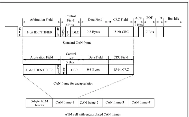
The proposed remote bridge encapsulates CAN frames into ATM AAL5 cells and transmits the cells across an ATM LAN backbone. At the other end of the backbone network, another remote bridge receives the ATM cells and de-capsulates the CAN frames, and forwards them onto the destination CAN segment (7, 8). In a standard CAN frame there are fixed fields and when these fields are extracted, a 12-byte field, maximum size for a standard CAN frame, can be used for encapsulation. Figure 1 illustrates the CAN and ATM frame formats as well as the encapsulation process. As an AAL5 cell has a 48-byte payload field
for encapsulation, four CAN messages can be placed in a single ATM cell. On the other hand, it is not always feasible to await CAN frames to complete a full four-frame encapsulation over long time periods, as it deteriorates the feature of a real-time system. In order to limit the encapsulation period, an encapsulation timer has been used. If four CAN messages are ready for encapsulation within the allowed time, the bridge encapsulates and forwards them immediately. On the other hand, if less than four messages are received within the allowed time, the encapsulation timer triggers the bridge to send the ATM cell with less than four encapsulated CAN messages. This will ensure that the F S O 11-bit IDENTIFIER RT R I D E 0r DLC 0-8 Bytes 15-bit CRC
Arbitration Field ControlField Data Field CRC Field ACK EOF Int Bus Idle
6 Bits 2 Bits 7 Bits 11-bit IDENTIFIER RT R I D E DLC 0-8 Bytes 15-bit CRC Arbitration Field ControlField Data Field CRC Field
5 Bits
Standard CAN frame
CAN frame for encapsulation
5-byte ATM
header CAN frame-1 CAN frame-2 CAN frame-3 CAN frame-4 ATM cell with encapsulated CAN frames
Figure 1. Encapsulation of CAN frames into ATM cells.
7.____.__I _
____._I ___.____._I 1 ___.___I ___._________,__________.___.I 1
1 1
·· ... ·· .... ···• ... ···-... ·•, .. 1 1 1 ···-.... . ... •··· ... •··· . ... •
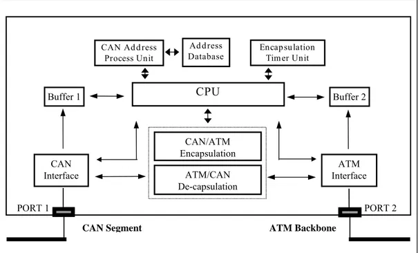
real-time requirements of the system are met. The timer can also be adjusted according to the congestion status of the backbone. The simplified bridge functionality block diagram can be seen in Figure 2.
3. MODELING AND SIMULATION
The proposed system has been implemented in a simulation environment using commercially available network simulation tool and the results have been evaluated. As can be seen from Figure 3, two CAN segments have been interconnected over an ATM backbone using remote bridges. The CAN segments were operated at the bus speed of 1Mbps. 25.92 Mbps STS-1/2 standard was chosen as the ATM backbone speed for a LAN environment. Permanent virtual
connection (PVC) is considered to be connecting the two remote bridges in the model to reduce latency.
In the model, when a remote bridge receives a
CAN message from the adjacent segment, it first checks its identifier field to decide whether it is to be forwarded. The forwarding database keeps the list of messages to be encapsulated into the ATM cells. A database search process known as acceptance filtering used in CAN systems is applied. The CAN frames that pass the acceptance filtering are buffered and prepared for encapsulation. After CAN messages to be forwarded are received, these messages are prepared for encapsulation as explained in the previous section.
PORT 2 PORT 1
CAN Segment ATM Backbone
CAN Interface ATM Interface
CPU
CAN Ad d ress Process Unit Encap su lation Tim er Unit Buffer 1 Buffer 2 Ad d ress Database CAN/ATM Encapsulation ATM/CAN De-capsulationFigure 2. Simplified functional block diagram of a CAN/ATM remote bridge
ATM Backbone CAN/ATM Remote Bridge-1 CAN/ATM Remote Bridge-2 CAN Segment-1 CAN Segment-2
Figure 3. CAN/ATM remote bridging model
____
ı
..
CJ
. . . _ _ I _ _ _ _ _ _ .*
ı
ı
ı
•
•
1 1•
•
ı
ı
r
_j
r ___
J _____
r
L
r
Encapsulated CAN frames are forwarded in ATM cells onto the ATM backbone. When the other remote bridge receives the cells, they are de-capsulated and CAN frames are prepared for transmission over the destination segment. In this process, the messages are transmitted in order and according to their priorities so as to reduce the latency of the high priority messages.
4. PERFORMANCE ANALYSIS
The model was operated under various traffic loads and results were compared with a benchmark table. The SAE (Society of Automotive Engineers) Benchmark was used to evaluate the CAN system. The Benchmark table gives different priority messages with different transmission periods (T) and different deadline (D) values. The benchmark describes 53 message types, which can be classified in 17-message groups (9). In the following, a brief explanation on the basic delay sources of a CAN message is provided.
TTd = TB1 + TEc + TBb + TDc + TB2
where,
TTd : end-to-end message transfer delay
TB1 : message delay on bus-1
TEc : encapsulation delay
TBb : backbone delay
TDc : de-capsulation delay
TB2 : message delay on bus-2
TB1 = tm + Cm (the same applies for TB2 )
tm : queuing delay
Cm : transmission time on bus (9).
bit m m m s T s c ⎭ ⎬ ⎫ ⎩ ⎨ ⎧ + + ⎥⎦ ⎤ ⎢⎣ ⎡ + = 47 8 4 34 where,
sm : size of message m in bytes
Tbit : bit time of the bus
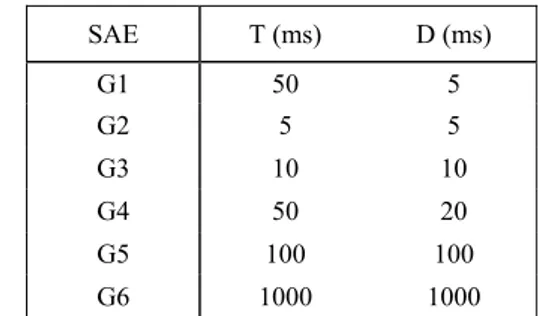
The message latency on one CAN segment is the total of the queuing delay and the transmission time on the bus. The queuing delay for a message depends on its priority (9). Table 1 provides a summary of the benchmark priority group classification, where T is the transmission interval, and D is the message deadline. Table 2 illustrates the end-to-end latency results of messages at different bus load rates. The messages are given as p1 to p8 according to priority order. As can be seen from the table, the message latencies meet the benchmark latency requirements even at very high bus load rates. Only the lowest two messages exceed 10 ms and 20 ms deadlines at 99% utilization, but they still meet the deadline limits for the low priority message deadlines of the benchmark.
Table 1. Message latency for SAE Benchmark.
SAE T (ms) D (ms) G1 50 5 G2 5 5 G3 10 10 G4 50 20 G5 100 100 G6 1000 1000 Table 2. End-to-end average message latency values (µs) for
different priority messages. System Throughput 19 % 46.6 % 69.1 % 88 % 95.7 % 99.5 % p1 343 365 386 415 428 444 p2 345 373 424 475 503 525 p3 347 378 458 492 572 669 p4 349 379 527 563 620 722 p5 352 399 475 617 741 886 p6 358 405 509 653 770 895 p7 362 427 634 1406 3710 10609 p8 368 434 883 1425 4522 38498
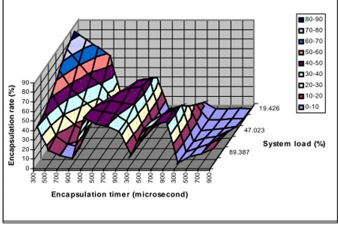
Because of the encapsulation timer and the superior backbone speed, the traffic levels within the ATM backbone do not play a significant role in the message latency. Figure 4 shows the rates of encapsulated CAN frames at different message load conditions with different encapsulation timer values. The figure shows the rates of encapsulation from 1 to 4 messages respectively from left to right between 300 and 900 microsecond encapsulation times. That is, first division from 300 to 900 microsecond encapsulation time on the left side shows one CAN message encapsulation rate, second division of 300 to 600 microsecond shows two CAN message encapsulation rate and so on.
At low message load rates and low encapsulation time values, the number of one CAN message encapsulation is high. This is because the arrival rate of CAN messages is low and the encapsulation timer will expire mostly after arrival of a single CAN message. This effect can be seen in the first division on the left side corner of the figure, where most of the single message encapsulation occurs. On the other hand, as the message load and encapsulation time increases, by the end of allowed time there will be more than one CAN message ready for encapsulation. Therefore, as can be seen from the figure the rate of more CAN messages encapsulated in a single ATM cell also increases. In the second division it can be seen that there will be more regular distribution of two-message encapsulation ratio over the message load and encapsulation time values. That is, at low and high message load and encapsulation time values the two-message encapsulation rate shows only slight differences, and mostly about 30 to 45% of
the ATM cells will encapsulate two CAN messages. The third division of the figure shows that only at high message load and encapsulation time values there will be higher three-message encapsulation rate. In the fourth division, it can be seen that very low four-message encapsulation rate occurs. From these results, it is possible to optimize the system by adjusting the encapsulation time according to message load.
0 10 20 30 40 50 60 70 80 90 E nc a ps ul a ti on r a te (%) 19.426 47.023 89.387 300 500 700 900 300 500 700 900 300 500 700 900 300 500 700 900 Syste m loa d (%)
Enca psula tion tim e r (m icrose cond)
80-90 70-80 60-70 50-60 40-50 30-40 20-30 10-20 0-10
Figure 4. Effect of CAN bus load and encapsulation timer on message latency.
5. CONCLUSION
In this paper it is proved that bridging CAN over an ATM (AAL5) backbone is feasible. Despite its ideal features in real-time control environments, CAN has limited bus length due to its medium access and error handling mechanisms. This study introduced a new method to extend the CAN system distance and, meanwhile, to provide an opportunity to transmit CAN messages over ATM networks. The method used employs the remote bridging technique that encapsulates CAN messages into ATM cells and transmits them over the ATM backbone. This method is
considered to fill a gap through the interconnection of Fieldbus networks and ATM. Simulation results showed that with right encapsulation and timing strategies, it is feasible for CAN systems to communicate over ATM in real-time.
6. REFERENCES
1. CAN Specification, Version 2.0, Robert Bosch GmbH, Germany 1991.
2. Tietze, H., “Connection between CANopen and Ethernet”, CAN Newsletter, September 2000, pp 26-28.
3. Thomas, G. M., “Real-Time Performance of Bridged CAN Networks”, CAN Newsletter, September 1998, pp 50-52. 4. Kunert, O., Zitterbart, E., “Interconnecting Field-buses
through ATM”, 22nd IEEE Conference on Local Computer
Networks, Minnesota 1997, pp 538-544.
5. Kunert, O., Zitterbart, M., “Performance aspects of Profibus Segments Interconnected through ATM”, SYBEN’98 - Symposium on Broadband European Networks”, Germany 1998, pp 337-345.
6. Pandya, A. S., Sen, E., “ATM Technology for Broadband Telecommunication Networks,” CRC Press LLC, USA 1999.
7. Tenruh M., Stipidis E., English M.J. “Performance Analysis of CAN/ATM Bridging”, CAN Newsletter, Issue 3, September 2000, pp.24-25.
8. Tenruh M., Stipidis E., English M.J., “Extending Controller Area Networks over ATM”, ISCIS’2000 The 15th International Symposium on Computer and
Information Sciences, İstanbul, Turkey, October 2000, pp 235-242.
9. Lawrenz, W., “CAN System Engineering: From Theory to Practical Applications”, Springer-Verlag Inc., New York 1997.
• • • • • • • • •