PEPTIDE NANOSTRUCTURE TEMPLATED GROWTH
OF IRON PHOSPHATE NANOSTRUCTURES FOR
ENERGY STORAGE APPLICATIONS
A THESIS SUBMITTED TO
THE GRADUATE SCHOOL OF ENGINEERING AND SCIENCE
OF BILKENT UNIVERSITY
IN PARTIAL FULFILLMENT OF THE REQUIREMENTS FOR
THE DEGREE OF
MASTER OF SCIENCE
IN
MATERIALS SCIENCE AND NANOTECHNOLOGY
By
Hepi Hari Susapto
December, 2015
PEPTIDE NANOSTRUCTURE TEMPLATED GROWTH OF IRON
PHOSPHATE NANOSTRUCTURES FOR ENERGY STORAGE
APPLICATIONS By Hepi Hari Susapto December, 2015
We certify that we have read this thesis and that in our opinion it is fully adequate, in scope and in quality, as a thesis for the degree of Master of Science.
Assoc. Prof. Dr. Mustafa Özgür Güler (Advisor)
Asst. Prof. Dr. Tarık Baytekin
Assoc. Prof. Dr. İlknur Tunç (THK Univ.)
Approved for the Graduate School of Engineering and Science:
Prof. Dr. Levent Onural Director of the Graduate School
ABSTRACT
PEPTIDE NANOSTRUCTURE TEMPLATED GROWTH OF
IRON PHOSPHATE NANOSTRUCTURES FOR ENERGY
STORAGE APPLICATIONS
Hepi Hari SusaptoM.S. in Materials Science and Nanotechnology Advisor: Assoc. Prof. Dr. Mustafa Özgür Güler
December, 2015
The use of primary cells has been replaced with rechargeable batteries due to environmental concerns. Li-ion batteries are examples of the rechargeable batteries that have replaced other types of rechargeable batteries from market due to high capacity, high electrochemical potential, superior energy density, durability, as well as the flexibility in design. Compared to other cathode materials used in Li-ion batteries, the iron oxide (FePO4) is less toxic, environmentally friendly, and less expensive.
Inorganic materials can be fabricated by template-directed mineralization to enable control over size and morphology. One-Dimensional (1-D) nanostructures can be used for template directed mineralization method. The nanostructures are particularly interesting as electrode materials due to their high surface area, large surface-to-volume ratio, and favorable structural stability. They provide fast ion/electron transfer by sufficient contact between the active materials and electrolyte.
In this thesis, 1-D nanostructures of FePO4 materials with high surface area were synthesized to enhance the efficiency of Li-ion batteries. The synthesis of iron phosphate nanostructures was performed by using peptide amphiphile nanostructures. Iron (III) chloride (FeCl3) was used to trigger the self-assembly of the peptide amphiphile molecules forming nanostructures, which can nucleate FePO4 formation. The electrochemical performance of
these nanostructures for Li-ion battery was analyzed. In conclusion, the template directed electrode materials revealed fast ion/electron transfer and sufficient contact between materials and electrolyte. They also exhibited enhanced flexibility leading to higher capacity than the electrode material synthesized without the template.
Keywords: Peptide amphiphile, Self-assembly, Hydrogel, One-dimensional Nanostructure, Nanofiber, Nanobelt, Template-directed materials, Iron phosphate, Lithium-ion batteries
ÖZET
PEPTİT NANOYAPI ŞABLONUYLA ENERJİ DEPOLAMA
UYGULAMALARI İÇİN DEMİR FOSFAT NANOYAPILARIN
GELİŞTİRİLMESİ
Hepi Hari SusaptoMalzeme Bilimleri ve Nanoteknoloji, Yüksek Lisans Tez Danışmanı: Doç. Dr. Mustafa Özgür Güler
Aralık, 2015
Şarj edilebilir piller, çevre dostu kullanımları sebebiyle birincil hücrelerin kulanımının yerine geçmişlerdir. Lityum-iyon piller, yüksek elektrokimyasal potansiyelleri, yüksek enerji yoğunluğu, dayanıklılığı ve esnek tasarlanabilirlikleri sayesinde piyasadaki diğer şarj edilebilir bataryaların yerini alan pil örneklerinden birisidir. Diğer katot malzemelere kıyasla, Li-iyon piller kullanılan demir oksit (FePO4) daha az toksik, çevre dostu ve daha ucuzdur.
Anorganik malzeme üretiminin yollarından biri, malzeme boyutu ve yapısı üzerinde kontrol sağlamayı kolaylaştıran, şablon-yönelimli mineralizasyon yöntemi kullanmaktır. Tek boyutlu (1-D) nanoyapıların üretilmesi, kullanınlan şablonun özelliği gözönünde bulundurularak mümkündür. Nanoyapılar özellikle, aktif madde ve elektrolit arasında yeterli teması sağlayarak hızlı iyon/elektron transferini destekleyen geniş yüzey ve hacim oranları ve yapısal kararlılıkları sayesinde ilgi çekmektedirler.
Bu bağlamda, lityum iyon pil verimliliğini artırmak için, geniş yüzey alanına sahip tek boyutlu demir fosfat (FePO4) nanomalzemeler, sentezlenmiştir. Demir fosfat nanoyapılarının sentezi, iki farklı peptit amfifil kullanılarak yapılmıştır. Demir (III) klorür (FeCl3), peptit amfifil moleküllerinin kendiliğinden biraraya gelmesini başlatmak için kullanılmış ve sonrasında kendiliğinden biraraya gelen bu nanoyapı, FePO4’ın nükleasyon bölgesini oluşturmuştur. Beta yaprağı ikincil yapı oluşturan bu peptitler, organik-anorganik çekirdek kabuk
(core-shell) malzemeleri için esas teşkil eden nanoyapıların oluşumunu sağlamaktadır. Kalsinasyon, peptidi uzaklaştırılmak için yapılmıştır. Li-iyon pilleri için kullanılan katot film, tek boyutlu demir fosfat şsblon ile çok-duvarlı karbon nanotüplerinin (MWNT) karışımı ile hazırlanmıştır. Sonuç olarak, bu şablon-yönelimli elektrot malzemesi, hızlı iyon/electron transferi, malzeme ve elektrolit arasında yeterli temas ve geliştirilmiş esnekliğin yardımıyla şablon olmadan üretilen elektrot materyalinden daha yüksek toplam kapasite sunmaktadır.
Anahtar sözcükler: Peptit amfifil, Kendiliğinden düzenlenme, Hidrojel, Tek-boyutlu nanoyapılar, Nanofiber, Nanobelt, Şablon-yönelimli malzemeler, Demir fosfat, Lityum iyon piller.
ACKNOWLEDGEMENT
I would like to express my gratitude to my advisor, Assoc. Prof. Dr. Mustafa Özgür Güler, for his utmost support, patience, motivation, and immense knowledge. His guidance helped me in all the time of research and writing this thesis. I am really fortunate to have worked in his research group.
I acknowledge Dr. Ruslan Garifullin, Dr. Ashif Shaikh, Ulaş Kudu, Dr. Özlem Erol, and Dr. Eda Yılmaz for their team work and hardship to make this research project successful. I would like also to express my special gratitude to Assoc. Prof. Dr. Ayşe Begüm Tekinay for her ideas and advices that help me understand more about research. I want to express my thanks to Assoc. Prof. Dr. İlknur Tunç for letting me work with her. I learned many things from her during our collaboration. I would like to express my thanks to Asst. Prof. Dr. Tarık Baytekin for the insightful discussions. It was a great pleasure to have him in the jury of my thesis.
I would like to express my thanks to Aygül Zengin, Meryem Hatip, Arif Khalily, Gülcihan Gülseren, Melis Şardan, Göksu Çınar, Alper Devrim Özkan, Ahmet Emin Topal, Gülistan Tansık, and other members of the Biomimetic Materials and Nanobiotechnology groups for sharing knowledge and giving excellent support. This thesis could not be written without the excellent support I have had from them.
I would acknowledge TÜBİTAK (Grant No. 113M900) and the 2215-TÜBİTAK Graduate Scholarship for International Students for the research funds.
I would like to express my heart-felt gratitude to my beloved family: my father, my mother, and my brothers. None of this would have been possible without the love and patience of my family. Their endless support and pray for me has strengthened me the most.
I am very grateful to all people I have met along the way and have contributed to the development of my research. In particular, I would like to show my gratitude to Nenden Octavarulia Shanty for her advice and assistance.
Finally, I would like to express my thanks to Amdya Mashfufah Hisyam for her unflagging love and unconditional support throughout my life and my studies.
TABLE OF CONTENTS
ABSTRACT ... iii ÖZET ... v ACKNOWLEDGEMENT ...vii TABLE OF CONTENTS ... ix TABLE OF FIGURES ... xiLIST OF ABBREVIATIONS ... xiii
1. INTRODUCTION ... 2
1.1. Rechargeable Lithium-Ion Batteries ... 2
1.1.1. LiFePO4 ... 3
1.1.2. FePO4 ... 4
1.2. Modification to enhance cell performances... 5
1.3. Template-Directed Growth of Materials ... 8
1.3.1. Hard Templates ... 8
1.3.2. Soft Templates... 10
1.4. Peptide Amphiphile (PA) Nanofibers ... 11
1.4.1. Design of Peptide Amphiphile Molecules ... 12
1.4.2. Synthesis of Peptide Amphiphile Molecules ... 13
1.5. Applications of Self-Assembly Peptide Amphiphile Molecules ... 13
1.5.1. Regenerative Medicine ... 14
1.5.2. Drug and Gene Delivery ... 15
1.5.3. Hybrid materials ... 15
1.5.4. Template in Synthesis of Inorganic Materials... 16
1.6. Purpose of the Experiment ... 17
2. RESULTS AND DISCUSSION ... 20
2.1. Materials and Method ... 20
2.1.2. Chemical and Reagents of Iron Phosphate Synthesis ... 20
2.1.3. Chemical and Reagents of Lithium-Ion Battery ... 20
2.2. Instrumentation ... 21
2.2.1. Liquid Chromatography – Mass Spectroscopy (LC-MS) ... 21
2.2.2. Preparative – High Performance Liquid Chromatography (Prep-HPLC) ... 21
2.2.3. Critical Point Dryer (CPD) ... 21
2.2.4. Circular Dichroism (CD) ... 22
2.2.5. Environmental – Scanning Electron Microscopy/Energy Dispersive X-Ray Analysis (E-SEM/EDX) ... 23
2.2.6. Transmission Electron Microscopy (TEM) and Scanning Transmission Electron Microscopy (STEM) ... 23
2.2.7. X-Ray Photoelectron Spectroscopy (XPS) ... 24
2.2.8. X-Ray Diffractometer (XRD) ... 24
2.2.9. Fourier Transform – Infrared Spectroscopy (FT-IR) ... 24
2.2.10. Thermal Gravimetric Analysis (TGA) ... 24
2.2.11. Inductively Coupled Plasma – Mass Spectrometry (ICP-MS)... 25
2.2.12. Multichannel Battery Testing System ... 25
2.3. Peptide Synthesis ... 25
2.4. Iron Phosphate Nanostructures Produced by Mineralization of Peptide Amphiphile Nanostructures ... 29
2.5. Lithium-Ion Battery Preparation ... 31
2.6. Results and Discussion ... 33
3. CONCLUSION ... 64
BIBLIOGRAPHY ... 68
APPENDIX 1 Copyright Clearance Agreements ... 83
APPENDIX 2 EDX Quantification ... 84
TABLE OF FIGURES
Figure 1.1. A schematic illustration of rechargeable Li-ion batteries 2
Figure 1.2. The crystal structure of olivine phases LiFePO4 in projection along
[001] 3
Figure 1.3. The modification methods to enhance the cell performances of Li-ion
battery 5
Figure 1.4. Electronic conductivities of cathode materials of Li-ion batteries 7
Figure 1.5. Nanocomposites of LiFePO4 7
Figure 1.6. Schematic illustration of template synthesis for hard and soft
templates 9
Figure 1.7. 3-D networks of PA nanofibers 12
Figure 2.1. Synthetic pathway of E-PA 27
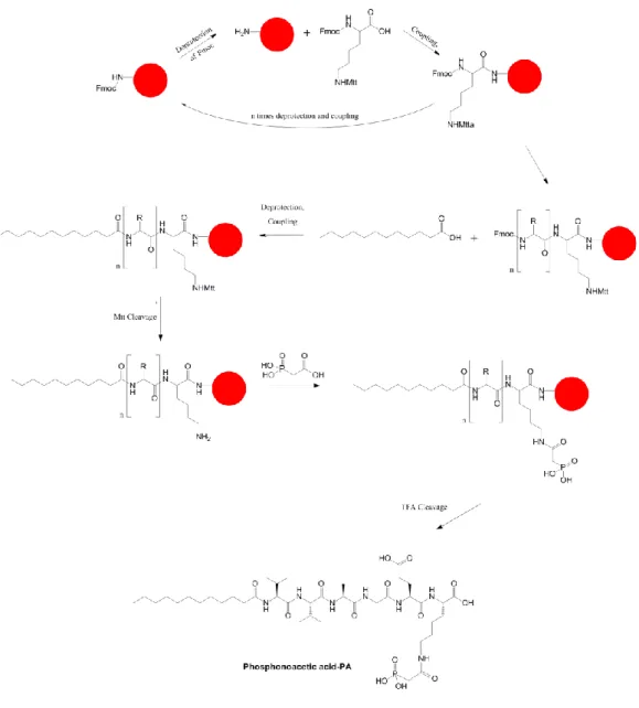
Figure 2.2. Synthetic pathway of Phos-PA 28
Figure 2.3. Schematic illustration of producing organic-inorganic core-shell of
templated FePO4 29
Figure 2.4. The preparation of template-directed FePO4 materials 30
Figure 2.5. Lithium-ion battery preparation 32
Figure 2.6. Chemical structures of peptide amphiphile molecules 34
Figure 2.7. Characterization of E-PA by using LC-MS 35
Figure 2.8. Characterization of Phos-PA by using LC-MS 36
Figure 2.9. The hydrogels formation of peptide amphiphile molecules 38
Figure 2.10. Circular dichroism spectra of the secondary structure of peptide
amphiphile interactions 39
Figure 2.11. STEM and TEM images of self-assembly of peptide amphiphile
molecules induced by acidic pH and inorganic materials 41
Figure 2.12. SEM images of peptide amphiphile molecules coated with inorganic
materials 44
Figure 2.13. EDX spectrum of FePO4-coated peptide amphiphile molecules 45 Figure 2.14. STEM images of Non-calcined and Calcined FePO4 hybrid materials
Figure 2.15. Schematic illustration of organic-inorganic core-shell templated
FePO4 formation 48
Figure 2.16. FT-IR spectra of the FePO4 samples 50
Figure 2.17. TGA of organic inorganic core-shell composite structure 51
Figure 2.18. XRD patterns of organic-inorganic core-shell composite structures
and template-free FePO4 52
Figure 2.19. XRD pattern of calcined organic-inorganic core-shell composite
structures at 600 °C for 2 h 53
Figure 2.20. XPS spectra survey profile of organic-inorganic core-shell
materials 54
Figure 2.21. XPS spectra core scan of calcined E-PA/FePO4 55
Figure 2.22. XPS spectra core scan of calcined Phos-PA/FePO4 56
Figure 2.23. The morphology of electrode film of Phos-PA/FePO4 and MWCT 58 Figure 2.24. Charge and discharge curves (5-7 cycles) of E-PA/FePO4 nanobelt as
a cathode of Li-ion batteries at different current rate 59
Figure 2.25. Charge and discharge curves (5-7 cycles) of Phos-PA/FePO4 nanotube as a cathode of Li-ion batteries at different current
rate 60
Figure 2.26. Discharge capacities of E-PA/FePO4 nanobelt, Phos-PA/FePO4
LIST OF ABBREVIATIONS
LiFePO4 : Lithium iron phosphate
FePO4 : Iron phosphate
1-D : One-dimensional
3-D : Three-dimensional
MWCT : Multi-walled carbon nanotube
PA : Peptide amphiphile
E-PA : Lauryl-VVAGE peptide amphiphile
Phos-PA : Phosphonoacetic acid peptide amphiphile
SPSS : Solid phase peptide synthesis
TFA : Trifluoroacetic acid
Fmoc : 9-Fluorenylmethoxycarbonyl tBoc : tert-Butoxycarbonyl HBTU : 2-(1H-Benzotriazol-1-yl)-1,1,3,3-tetramethyluronium hexafluorophosphate DIEA : N, N-Diisopropylethylamine DMF : Dimethylformamide DCM : Dichloromethane
FeCl3 : Iron (III) chloride
LiH2PO4 : Lithium phosphate monobasic NaH2PO4 : Sodium phosphate monobasic
LiTFSI : Lithium bis(trifluoromethanesulfonyl) imide
EC : Ethylene carbonate
DMC : Dimethyl carbonate
LC-MS : Liquid chromatography-mass spectrometry
Prep-HPLC : Preparative high performance liquid chromatography
CPD : Critical point dryer
CD : Circular dichroism
E-SEM : Environmental scanning electron microscopy
STEM : Scanning transmission electron microscopy
XPS : X-ray photoelectron spectroscopy
XRD : X-ray diffractometer
FT-IR : Fourier transform infrared spectroscopy
TGA : Thermal gravimetric analysis
CHAPTER 1
INTRODUCTION
1. INTRODUCTION
Lithium, which is known as the lightest metal can deliver high energy density per electron. It was first used as negative electrode material of primary lithium ion (Li-ion) cells in the 1970s [1]. The research on rechargeable Li-ion batteries itself, was started after the development of a series of intercalation compounds that can react reversibly with lithium [2]. These Li-ion batteries are preferred to other secondary batteries, such as lead-acid or nickel-cadmium batteries, due to long cycle life, high specific energy, and no memory effect leading to the most used of rechargeable power source in the wide variety of electronic devices [3].
1.1. Rechargeable Lithium-Ion Batteries
Figure 1.1. A schematic illustration of rechargeable Li-ion batteries
(Reproduced with permission from Reference [4]. Copyright 2008 American Chemical Society).
Discharge and charge in Li-ion batteries are two basic principles that exhibit the process of conversing and storing of electrochemical energy (Figure 1.1). For research purposes, the anode of Li-ion batteries usually consists of lithium-insertion/conversion compounds or lithium metal, while the cathode consists of Li+ host material that has more positive redox potential [5]. During discharging process,
the Li+ cations leave the anode through the electrolyte to intercalate the cathode providing the electrons to flow from anode to cathode. When the cell is charged, the electrons are provided to the anode allowing the Li+ cations to deintercalate in reverse from the cathode to anode. These conversion and storage of electrochemical energy depend on the diffusion of Li-ion between the cathode and the anode during the cycling process. Therefore, electrode materials that can accommodate a large amount of lithium and fast ionic/electronic transfer in the cell are required to obtain high specific capacity of the batteries [4].
Some works have been done to design new active materials with high reversible capacity, structural flexibility and stability, fast Li+ diffusion at high rate, low cost, less toxic, and environmentally friendly [3]. For example, lithium iron phosphate with olivine phases has been intensively studied as the cathode material due to high stability and conductivity that would be promising for rechargeable batteries [6, 7].
1.1.1. LiFePO4
Figure 1.2. The crystal structure of olivine phases LiFePO4 in projection along
[001] (Reprinted with permission from Macmillan Publisher Ltd: [2], copyright
The high capacity (170 mAhg-1), material abundance of iron, stability at high temperature, and high rate of charging are the advantages of using lithium iron phosphate (LiFePO4) with olivine structure as the cathode material for Li-ion battery [8]. The olivine structure enables the lithium to be extracted and inserted into LiFePO4 at low current density [9]. The high-rate charging of lithium iron phosphate comes from the large margin of voltage between working potential (Ew) of 3.45 V and charging voltage of 4.3 V. However, due to this low working potential, LiFePO4 exhibits low energy density (QEw) during discharge process. In addition, pure LiFePO4 behaves as insulator due to low ionic and electronic conductivities of lithium iron phosphate around 10-5 and 10-9 Scm-1, respectively. These low conductivities prevent the lithium iron phosphate to reach the theoretical capacity even at low discharge rates leading to poor rate capability [10, 11]. To overcome these problems, decreasing the particle size [12, 13], coating or making composites with conductive phases [14, 15], and doping with cationic or anionic ions can be employed [7].
1.1.2. FePO4
The intercalation and deintercalation mechanisms of LiFePO4 can be illustrated as the two-phase behavior of the LiFePO4/FePO4 system. By giving out 1 equivalence of lithium ion, lithium iron phosphate transform its phase into iron phosphate phase in which the structure is still same [16]. Thus, FePO4 is also available to be used as the cathode materials. There are also some advantages of using iron phosphate, such as inexpensive material, simple to be synthesized, environmentally friendly, and higher theoretical capacity (178 mA h g-1) [17]. However, the problems of LiFePO4 are still encountered also in FePO4, such as low electronic and ionic conductivities [18]. Amorphous structure of FePO4 is preferred to be used as cathode of Li-ion batteries than crystalline FePO4 that depends on the guest ion intercalate/deintercalate during charge/discharge process. The amorphous FePO4 maintains short-range structural ordering, improved kinetics, high surface area, and free volume which accommodate lattice distortions without producing macroscopic phase transition. These benefits increase specific capacities and provide stable electrochemical cycling over a wide potential window [19, 20].
1.2. Modification to enhance cell performances
Figure 1.3. The modification methods to enhance the cell performances of Li-ion battery (Reprinted from [21] with permissLi-ion from Elsevier).
During the charging process of LiFePO4, a Li-ion diffuses out of the cathode (ionic conductivity) allowing the Fe2+ ion to be oxidized into Fe3+ (electronic conductivity) [22]. These ionic and electronic conductivities affect the capacity and cell life of the cathode material, therefore it is important to enhance these values in order to improve the battery performances [10, 23]. Due to low ionic and electronic conductivities in LiFePO4 and FePO4, some methods have been developed in order to enhance these values (Figure 1.3).
Electrodes based on nanomaterials grant some advantages leading to the improvement of the battery performances [24, 25]. As the size of the electrode decreases to nanoscale, the length of the electronic and ionic transports becomes shorter leading to the enhancement in rate capabilities based on fast kinetics [13, 26]. Therefore, the charging time could be reduced allowing the batteries to be used longer even at higher power situations that make it beneficial for electric vehicles [8]. The electrode nanomaterials can also effectively accommodate the strain that come from the volume changes during lithium intercalation/deintercalation extending the cycle life of cells [27, 28].
Although the higher surface to volume ratio of nanomaterials provides more
reaction sites for lithium intercalation/deintercalation, undesirable
electrode/electrolyte reactions can be observed on the surface reducing the benefits of using electrode nanomaterials. A coating layer which is permeable to the lithium ion only can be adjusted on the surface to reduce the unwanted side reactions [29]. In addition, the nanomaterials also have disadvantage over the lower volumetric energy density due to the lower particle packing density [30]. To solve this problem, a composite electrode consisting of both nanotubes and nanoparticles can be prepared to obtain higher particle packing density [8].
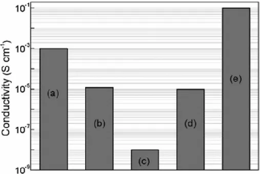
By introducing the conductive carbon materials to electrode materials either by coating or preparing composite material, the electronic conductivity can be increased significantly from 10-8 to 10-5 Scm-1 (Figure 1.4). Compared to carbon black which has been popularly being used as conductive agents in Li-ion batteries, carbon nanotube attributes its tubular shape and smaller surface area with higher electronic conductivity that has been applied in field emission and energy storage.
One-dimensional (1-D) nanostructures (nanowires, nanorods, nanotubes, and nanobelts) have become important for applications of energy conversion and storage such as in solar cells and Li-ion batteries [8]. They have larger surface area compared to their equivalent three dimensional structures [31]. Compared to a rod structure also, 1-D nanostructure containing tubular or hollow has more effective electrolyte contact area due to double-sided electrolyte diffusion leading to a better performance [8].
In Li-ion batteries, by adding multi-walled carbon nanotubes (MWCTs) to LiFePO4, the electronic conductivity can be improved [32]. MWCTs provide more facile electronic transport channels and also thermal and mechanical stabilities [33]. They construct strong webs with LiFePO4 particles making the composite electrode to be stable during the charge and discharge processes (Figure 1.5) [34].
Figure 1.4. Electronic conductivities of cathode materials of Li-ion batteries.
(a) LiCoO2, (b) LiMnO4, (c) LiFePO4, (d) nanocomposite of LiFePO4 and carbon black, and (e) nanocomposite of LiFePO4 and MWCTs (Reproduced from [8] with permission of The Royal Society of Chemistry).
Figure 1.5. Nanocomposites of LiFePO4. (a-c) With MWCTs, and (d) coating
with carbon nanofibers (Adapted from Reference [8] with permission of The Royal Society of Chemistry).
1.3. Template-Directed Growth of Materials
Synthesizing a material with controlled structure and desired function can be achieved by using a template [35-38]. For example, the electrode nanostructure materials with different morphologies (1-D nanostructures, 2-D films, and 3D interconnected porous architectures) can be synthesized by employing the template precursors. The template directed materials usually have small crystalline size, high surface area, large surface-to-volume ratio, and favorable structural stability that are favorable for electrode materials by providing fast ion/electron transfer, sufficient contact between active materials and electrolyte, and enhanced flexibility [4]. At the end, an improvement in electrode performances such as higher overall capacity, better high-rate capability, and longer cycling life can be expected from template-directed synthesized electrode materials.
The templates used in this synthesis can be divided into two types regarding the flexibility, which are hard template and soft template (Figure 1.6). The synthesis of template-directed materials contains three consecutive steps, which are: (1) impregnation or incorporation of precursors into the templates; (2) formation of solid species through reaction, nucleation, and growth; and (3) template removal to obtain the product [4].
1.3.1. Hard Templates
The structure of templated-directed material from hard templates is strongly affected by the connectivity of the pores or channels. For templates with isolated pores, such as AAO membranes and MCM-41 silica, the products are formed inside the isolated pores by filling the void space in templates [38]. After removing the template scaffold, aligned structures of 1-D nanotubes or nanowires are collected (Figure 1.6.a). On the other hand, the templates with continuous pores such as carbon or silica gels form product with interconnected 3D pores (Figure 1.6.b) [39]. Hard templates with isolated pores, especially AAO membranes are the most widely us hard templates due to facile preparation and controllable pore size [40, 41].
Figure 1.6. Schematic illustration of template synthesis for hard and soft templates (Reproduced with permission from [4]. Copyright 2008 American
Chemical Society).
The V2O5 electrode material for lithium batteries was the first material successfully prepared through hard template method [42]. The pore sizes of the product are in the range of 10 – 30 nm. The product with small pores shows higher capacities at higher discharge rates due to improved charge transports. Following the successful preparation of porous V2O5 material, other electrode materials have been prepared by using hard template, such as SnO2, LiNiO2, TiO2, Li4Ti5O12, LiMn2O4, LiFePO4, and porous carbon [43-48]. In order to improve the electrochemical properties of porous LiFePO4, carbon coating is performed to form
LiFePO4/C composites [49-52]. The preparation of porous LiFePO4/C composites can be done by using various organic templates as sacrificial hard templates, such as porous polycarbonate, mixed-cellulose, and cellulose [53].
1.3.2. Soft Templates
Soft templates can be utilized as structure-directing agents that assist in the assembly of reacting species. Due to their unique anisotropic structures and the functional groups, controlled fabrication of nanomaterials can be achieved easily by using the soft templates, such as surfactants, long-chain polymers, viruses, and peptide. These soft template materials can be assembled into micelle/vesicle aggregates or liquid crystal phase under certain conditions. The assembled materials restrict and direct the growth of a guest structure [54]. The guest structures react inside the confined space of surfactant micelles; while for polymer, virus chains, and peptide nanofiber, the reaction happens on the surface. The reaction between soft templates and the guest materials is driven by self-assembly of the template and interaction between functional groups of templates and guests [55, 56]. After the template removal, sphere-like/wire-like/tube-like structures can be obtained regarding the basic shape of the template aggregates.
Different types of biological soft templates have been employed in the fabricating of iron phosphate. A genetically engineered M13 virus was used to produce amorphous iron phosphate nanowires for the cathode of lithium-ion batteries [57]. The diameters of the produced iron phosphate are in the range of 10 to 20 nm. Using this negatively charged virus, the fabrication of iron phosphate could be done without thermal treatment through low-temperature. The electrochemical properties of the result materials were comparable with the iron phosphate treated at high temperature.
DNA was also studied as the platform for the direct growth of iron phosphate nanoparticles on the sugar-phosphate backbone of the DNA [58]. Double-walled carbon nanotubes were also used in this system to increase the conductivity of the iron phosphate. DNA is attached onto the double-walled carbon nanotubes via its aromatic bases. The capacity of the product is found nearly same with the theoretical storage capacity of iron phosphate.
The nanostructured iron phosphate is also able to be formed via biomimetic mineralization of peptide nanofibers [59]. These self-assembled peptide nanofibers contain acidic and polar moieties on the surface that act as the nucleation sites for the growth of inorganic iron phosphate. The iron phosphate mineralized peptide nanofibers were heated until 350 °C to form nanotubes with a thin layer of conductive carbon. The result materials perform high reversible capacity and good capacity retention.
1.4. Peptide Amphiphile (PA) Nanofibers
Amino acids that are the building blocks of peptide sequences and proteins contain an alpha carbon in the center where a hydrogen atom, an amino group, a carboxyl group, and a side chain are attached to alpha carbon [60]. Every amino acid has different side chain group leading to different structures, physicochemical properties, and biological functions of each amino acid. By considering the side chain groups, amino acids can be classified into charged, polar, non-polar, and aliphatic amino acids.
Two amino acids are attached to each other by the peptide bond (amide bond). This peptide bond is a covalent chemical bond formed between the carboxyl group of the first amino acid and amino group of another amino acid through condensation reaction with side product of water molecule. The synthesis of peptide (longer sequence of amino acids) can be conducted by using solid phase peptide synthesis method, which is easy to prepare and purify the peptide sequence. In the past, amino acids were not considered to be useful materials for materials engineering. However, after some recent developments in biotechnology, genetic engineering, and synthetic materials chemistry, the amino acids have been considered as promised building blocks for development of novel materials due to the ability of being a molecular self-assembly. Molecular self-assembly is the process of molecules to spontaneously organize into bigger and structured arrangements [61].
Peptide amphiphiles (PAs) are formed from the lipid chains attached to hydrophilic peptide sequences containing charged residues [62]. The peptide
amphiphile molecules tend to self-assemble forming β-sheet secondary structure allowing the formation of 1-D nanostructures through hydrogen bonding [63]. Not only 1-D nanostructure can be obtained, 3D networks are also formed from the self-assembled peptide amphiphile.
1.4.1. Design of Peptide Amphiphile Molecules
Figure 1.7. 3-D networks of PA nanofibers. (a) Chemical structure of
representative PA, (b) schematic representative of PA nanofiber formation, (c) SEM of 3-D network PA nanofiber, and (d) TEM of PA nanofibers (Reproduced with permission from [64]. Copyright 2008 John Wiley and Sons).
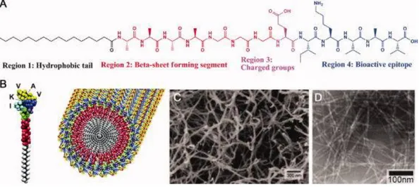
The PA molecules usually consist of four regions, which are a hydrophobic tail, a short β-sheet forming peptide sequence region, a charged amino acid region, and a bioactive epitope region (Figure 1.7) [65, 66]. The presence of hydrophobic tail, such as palmitoyl or lauryl groups generates the strongly amphiphilic nature of the PA [67]. The second region next to the hydrophobic tail is the short peptide sequence composed of hydrophobic amino acid residues. These hydrophobic amino acid residues tend strongly to form intermolecular hydrogen bonding in the form of β-sheet secondary structure leading to the 1-D nature of the self-assembled nanostructures that later entangle into networks [64]. The third region which is the charged amino acid residues adjacent to the β-sheet forming peptide sequence can be used as the functional region for the various purposes without changing the
cylindrical geometry. The number of charged amino acids in the sequence of PA is very critical since too much of charged amino acids can interfere the self-assembly of PAs into 1-D nanostructures under physiological conditions. On the other hand, charged amino acids are important in order to increase the solubility of the system in water. Due to the condition of charged amino acids that is relatively weak acids or weak bases, the self-assembly of peptide amphiphile into 1-D nanostructures can be induced by changing pH of the solution or raising the concentration of screening ions in the solutions [64]. The last region that is composed of bioactive epitopes is not always provided in PA sequence since it is usually only used in biomedical applications, such as tissue engineering, regenerative medicine, and drug delivery.
1.4.2. Synthesis of Peptide Amphiphile Molecules
The history of peptide was started 100 years ago when Emil Fischer and Ernest Fourneau synthesized the first peptide that was glycylglycine from glycine dihydride [68]. Nowadays, the most used technique for synthesizing longer sequence of peptide is solid phase peptide synthesis (SPPS). This method is based on the solid insoluble bead (resin) modified with linkers where the coupling process is started [69]. The protecting group at N-terminus of the amino acid such as 9-Fluorenylmethyloxycarbonyl (Fmoc) or tert-Butoxycarbonyl (t-Boc) is utilized to prevent the undesired reactions that may occur during the coupling process. The free unprotected N-terminus amino acid on the resins is coupled to C-terminus amino acid with protected N-terminus. The N-terminus is deprotected prior to coupling process with the next amino acid residue in the sequence. The consecutive steps of coupling, washing, deprotecting, washing are repeated until the desired peptide sequence is achieved. At the last step, the linker between the resin and peptide is cleavaged by using trifluoroacetic acid (TFA) solution in order to separate between the solid phase resin and the synthesized peptide solution.
1.5. Applications of Self-Assembly Peptide Amphiphile Molecules
Self-assembly is the process of smaller molecules associating into ordered 3-D structures via noncovalent interactions including hydrogen bonds, hydrophobic,
electrostatic, metal-ligand, π-π, and van der Waals interactions without the guidance of an external source [70]. Although the noncovalent interactions are the main reason of the self-assembly in which has lower energy than covalent bonds, the highly organized, and robust structures can be formed from these noncovalent interactions. The assembly can be found naturally in living cells, such as: self-assembly of lipids during cell membrane formation, protein folding, DNA double helix formation, virus formation, microtubules involved in cell division, and flagella in bacteria [71]. These self-assembly processes in nature are used as the inspiration for developing new biocompatible, biodegradable, and biofunctional materials.
Peptide amphiphile molecules are capable to self-assemble forming various well-ordered nanostructure materials due to the amphiphilic nature. In recent years, self-assembled peptide amphiphile molecules have been utilized in some applications, such as: regenerative medicine, drug, and gene delivery, hybrid materials, and template in synthesis of inorganic materials. Most of them are bioinspired and biomimetic materials that are designed by imitating the models, the systems, and the elements in nature.
1.5.1. Regenerative Medicine
By providing appropriate platform in regenerative medicine, new tissues can be formed at wound area with better healing process. In order to obtain the proper support materials, the self-assembled peptide amphiphile molecules can be employed as synthetic extracellular matrix materials. These extracellular matrix materials provide biological, chemical, and physical cues mimicking the natural environment of the cells.
The self-assembled peptides were used as the building materials of synthetic neural scaffold [72]. Two peptide molecules (laminin mimetic peptide amphiphile and heparan sulfate mimetic peptide amphiphile) were designed by mimicking neural extracellular matrix. The self-assembled nanofibers constructed from these peptide amphiphile molecules show the ability to promote neurite outgrowth of PC-12 cells even if there are inhibitory components of the central nervous system. Another type of peptide amphiphile molecule, glycosaminoglycan mimetic peptide
amphiphile was employed as a platform for cartilage regeneration [73]. The cartilage tissue has low regeneration capacity that brings a significant health problem. According to the results, glycosaminoglycan mimetic peptide amphiphile scaffold gives a promising result for cartilage regeneration.
1.5.2. Drug and Gene Delivery
Specific targeting and cellular internalization strategies for therapeutic agents can be achieved by using self-assembled nanostructures. Peptide functionalized liposomes [74] and nanofibrous peptide networks [75] are some examples of the peptide amphiphile molecules that can be used in smart drug delivery systems. Using these peptide molecules, enhanced efficacy of the drugs can be exhibited.
Liposomes are well known as drug nanocarriers due to their biocompatibility, biodegradability, and their cell membrane mimicking abilities [76]. The positively charged peptide amphiphile molecule was integrated into a negatively charged liposome in the presence of cholesterol via noncovalent interaction [74]. The peptide integrated liposome can be used as the carrier agent for anti-cancer drugs, doxorubicin-HCl, and paclitaxel in which the enhancement in liposomal uptake and efficacy of the drugs are observed.
A self-assembled peptide nanofibrous network was studied as the carrier platform for controlled delivery of oligonucleotide [75]. Oligonucleotide has been used as therapeutic agent for several disorders including cancer [77]. The network of the platform was prepared from cationic peptide amphiphile and oligondeoxynucleotide (ODN) via electrostatic interactions. Oligonucleotide release was controlled by changing the peptide amphiphile and oligonucleotide concentration in the PA-ODN network. According to the results, peptide amphiphile does not only control the ODN release, but also enhances the cellular uptake.
1.5.3. Hybrid materials
The peptide amphiphile molecules have been integrated to various types of nanoparticles via noncovalent interactions aimed at enhancing the function of the
specific nanoparticles. For example, integrated iron oxide [78] and mesoporous silica [79] can be applied for bioimaging and controlled drug delivery, respectively. These hybrid materials are able to be used in vitro experiment due to water soluble and biocompatible.
Magnetic resonance imaging (MRI) is a non-invasive method used for taking images of organs and structures inside the body via magnetic field and radio wave pulse. Some contrast agents with low toxicity level are functionalized to enhance the MRI signal, such as superparamagnetic iron oxide nanoparticles (SPIONs) [78]. In order to suppress the toxicity level of the SPIONs, peptide amphiphile molecules are used to coat the contrast agents via noncovalent interaction. According to the in vitro cell culture experiments, the peptide amphiphile molecules do not only enhance the biocompatibility and the solubility of the contrast agent but also can be used to target specific tissues.
Peptide amphiphile molecules were also employed in development of mesoporous silica nanoparticles (MSNs) in order to improve the cellular uptake and decrease the toxicity level [79]. The amphiphile molecules cover the hydrophobic organosilane surfaces of mesoporous silica nanoparticles. According to the result, 100 μg/mL of the hybrid material is non-toxic to the A10 cells and HUVEC.
1.5.4. Template in Synthesis of Inorganic Materials
The noncovalent interactions during the self-assembly process are important for constructing various self-organized supramolecular nanostructures. The peptide can be used as soft templates for synthesizing inorganic materials by mimicking the biomineralization process. The controlled fabrication of inorganic nanostructures over the size and structure can be obtained easily by using these types of templates. In addition, the modification of the template regarding the chemical functionality, architecture diversity, and physical properties can be done relatively easy [80, 81]. However, there are still some major problems with these templates, such as unstable at high temperature, liable with organic solvents, and easily degradable [82].
TiO2 and ZnO nanonetworks were prepared by bioinspired peptide nanofiber templates with high coating conformity, uniformity, and atomic scale size control [83]. The inorganic materials were deposited on the template surfaces using an atomic layer deposition technique. TiO2 and ZnO nanonetworks exhibit better photoexcitation properties compared to the unstructured TiO2 and ZnO materials due to the enhanced surface area with nanostructure morphology.
Due to versatile chemical and physical properties, the peptide amphiphile molecules were used in the synthesis of catalytic metal nanostructures [81]. The peptide nanofiber template Pd0 hybrid nanocatalyst was prepared for mild and efficient Suzuki-Miyaura coupling reactions. The Palladium ions coordinate to the peptide via lone pair electrons of side-chain of the amino acid residues in the peptide. The hybrid nanocatalyst shows high catalytic activity in Suzuki-Miyaura coupling reactions. In addition, the nanocatalyst is still able to be isolated and reused after 5 times reactions without loss in activity and structural integrity.
1.6. Purpose of the Experiment
The synthesis of different morphology of iron phosphate nanostructures was done by using two different peptide amphiphile molecules as the templates. The self-assembly mechanism of these peptides can be induced either by tuning the pH or introducing the metal ions into the systems that later can be observed from the formation of a hydrogel. In this study, the peptide amphiphile molecules triggered by Fe3+ ions can self-assemble to form β-sheet secondary structure leading to formation of nanostructure that is essential for the formation of organic-inorganic core shell materials. In addition, the functional groups at the periphery of the peptides can be used to attach the Fe3+ ions providing the nucleation sites for the growth of the inorganic material on the surface of template nanostructures. The growth of the inorganic layer of FePO4 should be kept by repeating the immersion cycles of the peptide hydrogel in the precursor solutions. Later, critical point dryer was used to change the physical form of the hydrogels into aerogels in order to remove the water content of the as-prepared materials. The aerogels should be calcinated in order to remove the peptide template and produce anhydrous product that is
preferred as the cathode materials. Analyses of the samples were performed by using some techniques, such as HPLC-MS, CD, TEM, STEM, E-SEM, FT-IR, TGA, XRD, XPS, and ICP. Finally, the electrochemical performances of each of different morphology of iron phosphate electrodes are analyzed and compared with each other.
CHAPTER 2
2. RESULTS AND DISCUSSION
2.1. Materials and Method
2.1.1. Chemical and Reagents of Peptides Synthesis
9-Fluorenylmethoxycarbonyl (Fmoc) and tert-Butoxycarbonyl (tBoc) protected amino acids, MBHA Rink Amide resin, Fmoc-Glu(OtBu)-Wang resin, and 2-(1H-Benzotriazol-1-yl)-1,1,3,3-tetramethyluronium hexafluorophosphate (HBTU) were purchased from NovaBiochem and ABCR. Lauric acid, N,N-diisopropylethylamine (DIEA), piperidine, acetic anhydride, and trifluoroacetic acid (TFA) were purchased from Merck. N,N-dimethylformamide (DMF), dichloromethane (DCM), and diethyl ether were purchased from Sigma-Aldrich. Triisopropylsilane and phosphonoacetic acid were purchased from Alfa Aesar. The chemicals were used as received, without any purification.
2.1.2. Chemical and Reagents of Iron Phosphate Synthesis
Iron (III) chloride (FeCl3) was purchased from Merck. Lithium phosphate monobasic (LiH2PO4) and sodium phosphate monobasic (NaH2PO4) were purchased from Sigma-Aldrich. Tris buffer with pH of 7.2 was prepared by mixing
Trizma Base (Tris(hydroxymethyl)aminomethane) and Trizma HCl
(Tris(hydroxymethyl)aminomethane hydrochloride) that were purchased from Sigma-Aldrich.
2.1.3. Chemical and Reagents of Lithium-Ion Battery
Multi-walled carbon nanotube (MWCT), lithium
bis(trifluoromethanesulfonyl) imide (LiTFSI), ethylene carbonate (EC), and dimethyl carbonate (DMC) were purchased from Sigma-Aldrich. Isopropanol was purchased from Merck. Nafion DE 520 was purchased from Dupont. Celgard C480 membrane was purchased from Celgard. Glass microfiber filter (GF/C) was purchased from Whatman.
2.2. Instrumentation
2.2.1. Liquid Chromatography – Mass Spectroscopy (LC-MS)
1 mL of water was used to dissolve 1 mg of peptides. The solutions were sonicated for 15 min. LC-MS measurements were performed using Agilent Technologies 6530 Accurate-Mass Q-TOF LC-MS with electrospray ionization (ESI) source equipped with reverse-phase analytical high performance liquid chromatography (HPLC). Agilent Zorbox Extend-C18 column was used together with mixture of two different solutions of 0.1% (v/v) ammonium hydroxide – water (A) and 0.1% (v/v) ammonium hydroxide – acetonitrile (B). The flow of mobile phase was 0.65 mL/min with composition of 98% A – 2% B at first 2 min. From 2 to 20 min, the flow of B increased until 100% B and turned back again to 2% again for the next 5 min. LC chromatogram was obtained at wavelength of 220 nm.
2.2.2. Preparative – High Performance Liquid Chromatography (Prep-HPLC)
An Agilent 1200 preparative reverse-phase HPLC system equipped with a Gemini 5u C18 110A column with size of 100× 21.20 mm 5 micron for negatively charged samples was used to purify the peptides. 0.1% (v/v) ammonium hydroxide – water (A) solution and 0.1% (v/v) ammonium hydroxide – acetonitrile (B) solution were mixed and used for the mobile phase. 100 mg of peptides were dissolved in 10 mL of 0.1% (v/v) ammonium hydroxide – water and injected into the system.
2.2.3. Critical Point Dryer (CPD)
Ethanol exchange was done before transferring the peptide gels into CPD in order to exchange the water content of the hydrogels with ethanol. Because water was immiscible in CO2, ethanol was used as the intermediate solvent to dehydrate the gels before being infiltrated by CO2. Ethanol is miscible in both water and CO2. The hydrogel samples were dehydrated in gradually increasing concentrations of 20%, 40%, 60%, and 80% (v/v) ethanol solutions for 10 min in each solution to
avoid the sample being shrunken and subsequently transferred to 100% ethanol for 2 h waiting period. The samples then were dried at the critical point of carbon dioxide (31 °C and 1072 psi) using the Tousimis Autosamdri-815 B, Series C critical point to obtain undamaged dry peptide network of the gel [84].
2.2.4. Circular Dichroism (CD)
The secondary structure of the peptide hydrogels was determined by using JASCO J815 CD spectrometer at room temperature. 1 mg of each peptide was diluted into 90 μL of double-distillated water and sonicated to achieve homogeneous solution. 10 μL of HCl and 10 μL of FeCl3 solutions were introduced into different flasks of peptide solutions leading to the formation of self-assembled hydrogels. The final concentration of self-assembled peptide hydrogels was 1% (w/v). This value was equivalent to 15.27 mM for E-PA and 11.06 mM for Phos-PA hydrogel. The peptide hydrogels (E-Phos-PA/FeCl3, E-PA at acidic pH, Phos-PA/FeCl3, and Phos-PA at acidic pH) were diluted until the concentration fell to 0.025% (w/v) that was around 3.818 x 10⁻⁴ M for E-PA and 2.765 x 10⁻⁴ M for Phos-PA.
Other samples such as peptide solutions at physiological pH (pH 7.4), E-PA/FePO4, and Phos-PA/FePO4 were also measured. In order to prepare peptide solution at neutral pH, 1 mg of peptide amphiphile molecules were diluted, sonicated in 100 μL of double-distillated water and subsequently diluted 40 folds. The preparation for E-PA/FePO4 and Phos-PA/FePO4 were done by diluting 1 mg of each peptide into 80 μL of double-distillated water. 10 μL of FeCl3 solution was dropped onto each peptide solution to form the hydrogel. Later, 10 μL of NaH2PO4 solution was introduced to each peptide hydrogel. Each of the hydrogels were then diluted 40 folds prior to measurement.
1 mm thick quartz was used to perform the measurements. Around 300 μL of diluted peptide mixture solutions were put into the quartz and measured from 300 to 190 nm, with data interval and data pitch of 0.1 nm, scanning speed of 100 nm/min, and three times of accumulations. Digital integration time (DIT) was selected as 1 s, bandwidth as 1 nm, and standard sensitivity.
Molar ellipticity [θ] with the unit of deg.cm-2.dmol-1 was calculated using the following equation:
[𝜃] =100 x 𝜃 𝐶 x 𝑙 Where, θ : measured ellipticity (mdeg),
C : peptide concentration (molar), l : cell path length (cm).
2.2.5. Environmental – Scanning Electron Microscopy/Energy Dispersive X-Ray Analysis (E-SEM/EDX)
The morphology of the fabricated samples was visualized by using FEI Quanta 200 FEG environmental scanning electron microscope with an ETD detector. The samples were sputter coated with 8 nm of gold/palladium prior to imaging. The EDX spectra of the samples were collected from the area at 300x magnification of the non-coated samples to obtain the chemical composition. The quantification of the EDX spectra was taken to obtain the Fe/P ratio in the samples.
2.2.6. Transmission Electron Microscopy (TEM) and Scanning Transmission Electron Microscopy (STEM)
The diluted samples which were casted on a Lacey mesh ultrathin carbon coated copper grid were put into FEI Tecnai G2 F30 for taking the transmission electron and scanning transmission electron micrographs. The samples were prepared by diluting 1% (w/v) of peptide hydrogels with double-distillated water to reduce the concentration until 0.025% (w/v) without any sonication then casted on the grids. Negative staining was performed using 2% (w/v) uranyl acetate for samples that did not contain any inorganic metal residue in order to get better contrast images. On the other hand, calcined samples that did not contain any organic template anymore were diluted in ethanol.
2.2.7. X-Ray Photoelectron Spectroscopy (XPS)
The surface characterization of organic-inorganic core-shell samples was done by using a Thermo Scientific XPS spectrometer with Al-Kα monochromatic (100 – 400 eV range) X-ray source and ultra-high vacuum (∼10 – 9 Torr). The sample powders were put on the cupper band to conduct the characterization.
2.2.8. X-Ray Diffractometer (XRD)
The crystal structure of the samples was studied by using PAN analytical X’Pert X-ray diffractometer with Cu Kα radiation. The sample powders were scanned in the range of 2θ = 10 – 60° and step size of 0.026°.
2.2.9. Fourier Transform – Infrared Spectroscopy (FT-IR)
The qualitative analysis of the samples was done by analyzing the infrared absorption spectrum of each sample in order to learn the interaction inside the samples. KBr pellet was prepared prior to measurement. In order to prepare KBr pellet, 1 mg of each non-calcined and calcined sample powders was pounded together with 100 mg of KBr. Bruker Vertex 70 FT-IR spectrometer was used for FT-IR analysis with wavenumber range from 4000 to 400 cm-1.
2.2.10. Thermal Gravimetric Analysis (TGA)
The percent composition of inorganic contents in templated FePO4 samples was determined by using a thermogravimetric analyzer (TGA) (Q500, TA Instruments). The temperature was ramped from 25 °C to 500 °C with 10 °C min−1 heating rate in the presence N2 gas. N2 gas was switched to O2 gas after the temperature reached 500 °C. The heating process was continued until 800 °C with the same heating rate of 10 °C min−1.
2.2.11. Inductively Coupled Plasma – Mass Spectrometry (ICP-MS)
The amount of iron molecules in the samples was determined by using Thermo Scientific X Series 2 ICP-MS. The value of iron amount will be used to predict the percentage of iron phosphate in the sample. Five different concentration of iron reference solutions (50, 100, 250, 500 and 1000 ppb) were prepared from 1000 ppm iron standard solution. 1 mg of each calcined sample (E-PA/FePO4, Phos-PA/FePO4, and template-free FePO4) was dissolved in 1 mL of conc. HCl and sonicated for 30 min. These solutions were then diluted by adding 2% (v/v) nitric acid until the content of iron in each solution reached 100 ppb by estimation. The exact amount of iron content for each sample was determined by interpolation on the calibration curve.
2.2.12. Multichannel Battery Testing System
Electrochemical testing of the cells was performed with a Landt CT2001A multichannel potentiostat/galvanostat. 5 discharge/charge cycles were applied to the cell with current rates of C/20, C/10, C/5, C, 2C, and C/20; where C represents the current rate at which the theoretical capacity was charged/discharged in 1 h. The voltage was limited in the range of 2.0-4.0 V.
2.3. Peptide Synthesis
Peptide amphiphile molecules were synthesized manually using the method of standard solid peptide synthesis. Two peptide amphiphile molecules, which were E-PA (C12-VVAGE-OH) and Phos-PA
(C12-VVAGEK(Phosphonoacetyl)-NH2) were synthesized on Fmoc-Glu(OtBu)-Wang resin and MBHA Rink Amide
resin, respectively (Figures 2.1 and 2.2). First, the resin was swelled with dichloromethane (DCM) solution inside the vessel and agitated for 30 min. Then, vacuum was applied to the vessel to remove DCM. Before attaching the first amino acid residue to the resin, the Fmoc-protected group on the resin was removed by treating the resin with 10 mL of 20% (v/v) piperidine/dimethylformamide (piperidine/DMF) solution for 20 min. Then the resin was washed with DCM and
DMF sequentially in prior to coupling process. In addition, the washing steps were always done after every finished step in order to remove the excess materials from the vessel. First amino acid couplings were performed by pouring the first C-terminal amino acid residue solution that contained of 2 equivalents of N-protected amino acid activated with 1.95 equivalents of HBTU and 3 equivalents of DIEA for each 1 equivalent mol of resin and agitated for at least 2 h. Kaiser Test was performed after each coupling to examine the presence of free amino group on the resin. When the Kaiser Test result showed dark blue color on the resin, it meant there was still free primary amine. The coupling process was repeated when this problem occurred. On the other hand, when there was no any dark blue color on the resin during the test, acetylation was subsequently performed by pouring 10% (v/v) acetic anhydride/DMF solution to the vessel in order to cover the undetectable free primary amine with the acetyl group. To start the second coupling, Fmoc protected group of the first amino was removed by adding 10 mL of 20% (v/v) piperidine/DMF and agitating for 20 min. These sequential steps that were amino acid coupling, washing, Kaiser Test, acetylation, and Fmoc cleavage were repeated until the last sequence of amino acids. The last amino acid was coupled with lauric acid in similar way to amino acid coupling.
For Phos-PA, the protected group (Mtt) at the end of lysine side chain was removed by using 10 mL of 3.25% TFA, 0.125% water, 0.125% triisopropylsilane, and 96.5% DCM. The cleavage was repeated for 5 – 6 times with 5 min shaking for each period. The vessel was washed with DCM and DMF in between the cleavage. The washing solution was collected to observe the changing color of the washing solution from fluorescent color to transparent after each cycle. When the transparent of washing solution was observed, Mtt protected group was successfully remove and 10 mL of DMF solvent that contained 50 μL DIEA was poured to the vessel as the final washing solution to remove excess the TFA from the vessel. Phosphonoacetic acid that was diluted in DMF together with DIEA and HBTU was poured into the vessel and shaken for 1 day in order to bind to the side chain of the lysine.
At the end, each peptide sequence was separated from the resin using a solution that contained of 95% TFA, 2.5% water, and 2.5% triisopropylsilane for
2 h. The vessel was washed only with DCM and collected into the round bottom flask. The removal of excess TFA and DCM from the peptide solution was carried out by using rotary evaporation. The left portion of peptide solution inside of round bottom flask was dispersed in diethyl ether for overnight. The next day, the peptide amphiphile was extracted from diethyl ether by centrifugation and transferred to double-distillated water. The peptide solution was frozen at -80 °C and then lyophilized to get the solid form of peptide. The peptide was purified by using prep-HPLC before being used.
2.4. Iron Phosphate Nanostructures Produced by Mineralization of Peptide Amphiphile Nanostructures
Figure 2.3. Schematic illustration of producing organic-inorganic core-shell of templated-FePO4.
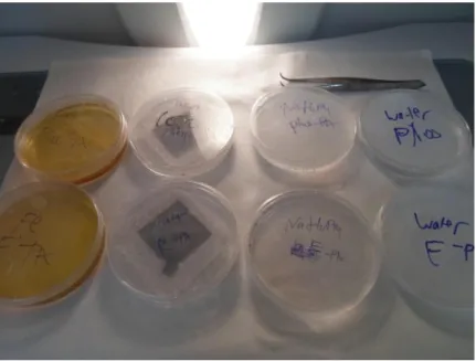
1 mg of each peptide amphiphile molecule was dissolved in different test tubes of 90 μL double-distilled water to form peptide solutions with concentration of 1.11% (w/v). The solutions then were poured on the silicon wafers that had been immersed in piranha solution. This piranha solution increases the content of hydroxyl group on the surface of the silicon wafers and also cleans the surface from the organic content. The peptide hydrogels were formed by dropping 10 μL of iron chloride solution (FeCl3) onto the peptide solutions. The concentration of iron chloride solution for E-PA and Phos-PA was 305.78 mM and 246.91 mM, respectively. The final concentration of peptide in each hydrogel was 1% (w/v). The molar concentrations of these 1% (w/v) peptide hydrogel were 15.27 mM and 11.06 mM for E-PA and Phos-PA, respectively. After waiting for 5 min at temperature of 4 °C, each hydrogel was immersed for 30 min in iron chloride solution which had the same concentration as the previous iron chloride. The hydrogels then were transferred to water batch to remove the excess iron solution on the hydrogel and waited for 15 min. Next, the hydrogels were immersed to
sodium phosphate (NaH2PO4) solution for 30 min. The molar concentrations of sodium phosphate for E-PA and Phos-PA hydrogel were 305.78 mM and 246.91 mM, respectively. The yellowish hydrogels started to form white precipitation directly after being treated with NaH2PO4 solutions. Then, the hydrogels were washed again with water by waiting in water solution for 15 min. These steps were repeated again until four cycles. All of the processes were done at low temperature (~4 °C) in order to suppress the hydrolysis of Fe3+ ions.
After finishing the fourth cycle, the hydrogels were dehydrated using ethanol solution before being transferred to CPD in order to form aerogels which were more stable than hydrogels. The thermal treatment (calcinations) was done step by step in normal air atmosphere. The temperature was increased with heating rate of 5 °C/min until 250 °C and then brought to 350 °C with heating rate of 1 °C/min. The samples were kept at 350 °C for 1 h.
In addition, template-free FePO4 was also prepared by mixing the same concentration and volume of 246.91 mM of FeCl3 and NaH2PO4 using a magnetic stirrer for 30 min. The solution was kept inside the oven at 80 °C for overnight to evaporate the water content. The left powder was washed with distilled water and filtered on filter paper. The wet powder was calcined under the same procedure as the templated iron phosphate.
2.5. Lithium-Ion Battery Preparation
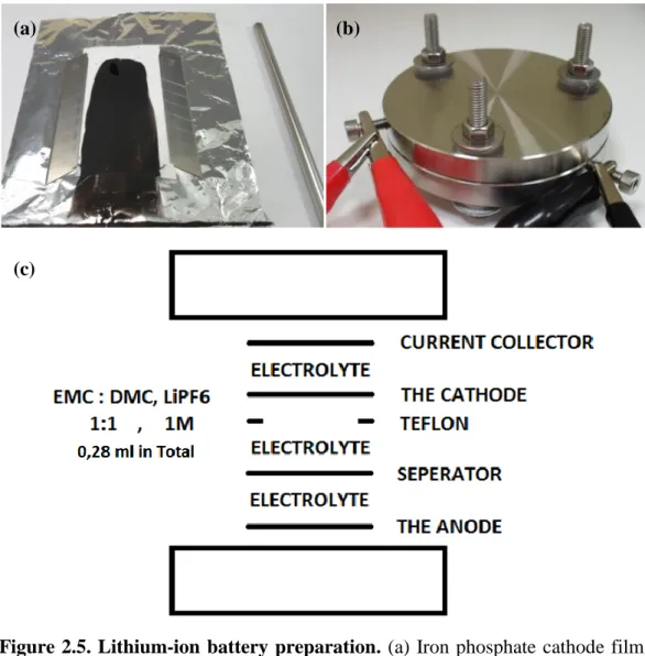
Templated FePO4 cathode films were produced with two different organic templates and tested against Li/Li+ electrode in coin cells. The cells were assembled in argon environment within the glovebox to prevent air exposure. The film cathode material was obtained by slurry casting, in which the FePO4 powder was ground together with multi-walled carbon nanotube (MWCT). Afterwards, Nafion binder was dropped to the mixture powder. The percent composition of the mixture according to the total mass of the mixture was 70%, 20%, and 10% of FePO4, MWCT, and Nafion, respectively. The mixture was dispersed in isopropanol and stirred for a couple of days using magnetic stirrer. The mixture solution was casted on a separator (Celgard) film to yield a desired thickness. The casted film was exposed to open air for 1 h, and then the drying process was continued at elevated temperatures (60 °C) for 8 h. Finally, the cathode material was obtained by cutting the film to desired shape and diameter.
A stainless steel current collector having 11 mm diameter was used in the assembly of cell for lithium part. As the counterpart, another stainless steel current collector having 12 mm in diameter was used. Two different separators were used in the cell that were Celgard separator at the Li anode and Glassfiber/C separator at the cathode film. 280 µL of 0.5 M LiTFSI EC-DMC (1:1) was used as electrolyte. After the cell was assembled in the Ar atmosphere, it was sealed to prevent the interaction with the atmosphere.
The cells were rested for 8 h in prior to testing in order to let the electrolyte to diffuse through the cell. Electrochemical testing of the cells was performed with a Landt CT2001A multichannel potentiostat/galvanostat. 5 discharge/charge cycles are applied to the cell with current rates of C/20, C/10, C/5, C, 2C and C/20, while the voltage was limited into 2.0-4.0 V.
Figure 2.5. Lithium-ion battery preparation. (a) Iron phosphate cathode film,
(b) electrochemical testing of the cells, and (c) schematic illustration of Li-ion battery.
(a) (b)
2.6. Results and Discussion
The iron phosphate materials were obtained by using organic materials as the templates. These organic materials were synthesized from different types of protected amino acids and hydrophobic alkyl chain by using Solid Phase Peptide Synthesis (SPPS) method to form materials that were called as peptide amphiphile molecules.
In this thesis, peptide amphiphile molecules contain three regions: a hydrophobic alkyl tail, a short sequence of peptide forming β-sheet and a charged head. The hydrophobic alkyl tail which is the reason of the amphiphilicity of the materials can be adjusted by using different alkyl chain lengths and different hydrophobic compounds [67]. The second region which is composed of hydrophobic amino acids has the capability to form intermolecular hydrogen bonding, generally β-sheets. It leads to the formation of nanofibers that later being entangled to form networks [64]. The last region that contains negatively charged amino acid serves as a template for the nucleation of iron phosphate on the surface of nanostructure by forming conjugates with Fe3+. This interaction between negatively charged amino acid and Fe3+ prevents the hydrolysis of iron ion [57].
Two different peptide amphiphile molecules that contained the alkyl chain, the short sequence of hydrophobic amino acids and the negatively charged amino acid were designed and synthesized. These peptide amphiphile molecules, lauryl-VVAGEK(Phosphonoacetyl)-Am [Phos-PA] and lauryl-VVAGE-OH [E-PA], were used as a template for FePO4 formation (Figures 2.6a, and b). The main difference between both of the peptide amphiphile molecules was the presence of phosphate group in Phos-PA that could directly conjugate with iron ion.
Figure 2.6. Chemical structures of peptide amphiphile molecules. (a) E-PA,
and (b) Phos-PA. Black color indicates hydrophobic alkyl tails, red color indicates β-sheet forming short peptide sequence, and blue color indicates charged head.
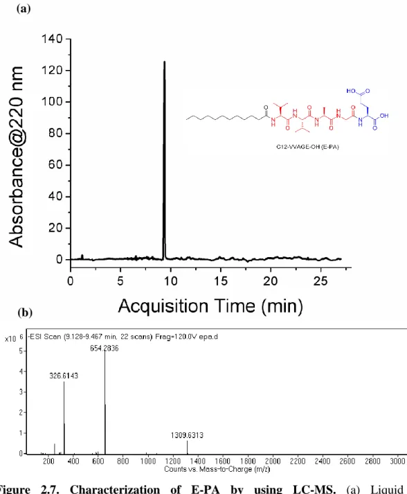
After the synthesis, the peptide amphiphile molecules were purified using Prep-HPLC after the synthesis aimed at separating the unintended materials from the mentioned peptides. The purified peptide amphiphiles were dissolved in double-distilled water with concentration of 1 mg/mL and then analyzed by using Q-TOF LC-MS to determine the final purity and molecular weight of the peptides. The chromatograms show that the purity of both peptides are more than 95% (Figures 2.7a and 2.8a). According to the mass spectra results of E-PA and Phos-PA, the molecular weights of E-PA and Phos-PA are found as 655 g/mol and 904 g/mol, respectively which are nearly the same with the calculated mass (Figures 2.7b and 2.8b).
(a)
Figure 2.7. Characterization of E-PA by using LC-MS. (a) Liquid
chromatogram of PA by the absorbance at 220 nm, and (b) mass spectrum of E-PA. MS: (m/z) calculated 655.42, [M-H]- found 654.2836, [M-2H]2- found 326.6143. [2M-H]- found 1309.6313.
(a)
Figure 2.8. Characterization of Phos-PA by using LC-MS. (a) Liquid
chromatogram of Phos-PA by the absorbance at 220 nm, and (b) mass spectrum of Phos-PA. MS: (m/z) calculated 904.50, [M-H]- found 903.3460, [M-2H]2- found 451.1433. [M-3H]3- found 300.4115.
(a)
1% (w/v) peptide amphiphile solutions were prepared by dissolving 1 mg of each of E-PA and Phos-PA in 100 μL of double-distilled water. Both of these peptide solutions start to self-assemble after the addition of HCl or metal ions that screen the negative charge of the peptides. Glutamic acid at both of E-PA and Phos-PA bears negative charges at physiological pH and shifts to uncharged state at acidic pH. Together with the other driving forces that are a hydrophobic interaction of alkyl chains and a hydrogen bonding, the peptide amphiphiles start to form aggregates. The self-assembly process of E-PA and Phos-PA at acidic pH is evaluated from the formation of hydrogels (Figure 2.9b, and f). By dropping 5 μL of 1M HCl into the peptide solutions, the hydrogel formation was able to be observed with naked eye. Phos-PA itself has a tendency to form a hydrogel in a couple of minutes even at physiological pH (pH 7.4) after sonication due to weaker electrostatic repulsion.
The hydrogels of E-PA and Phos-PA were also formed by introducing FeCl3 to induce the self-assembly of peptide amphiphile molecules (Figures 2.9c, and g). These 1% (w/v) E-PA/FeCl3 and Phos-PA/FeCl3 hydrogels were later mixed with NaH2PO4 to induce the formation of E-PA/FePO4 and Phos-PA/FePO4 (Figures 2.9d, and h). The latter hydrogels have paler yellow color due to precipitation of FePO4.
The secondary structures of self-assembled peptides were probed using circular dichroism (CD). The CD spectra give information about the absorption bands of optically active chiral molecules. In here, the results obtained from CD analysis show the formation of β-sheet structure for all of the self-assembled samples (Figure 2.10). The signals of β-sheet usually consist of minimum peak at 216 nm and maximum peak at 200 nm [85, 86]. The different type of peak is only observed for E-PA solution at physiological pH that shows the formation of a random coil with minimum peak signal at 195 nm. This random coil structure of E-PA disappears and transforms to β-sheet structure either by lowering the pH or introducing the iron ions indicating the self-assembly process. The CD result also explains the self-assembly process of Phos-PA at physiological pH due to the presence of β-sheet structural motif. This result supports the fact that Phos-PA forms hydrogel in a couple of minutes after dissolution.
![Figure 1.2. The crystal structure of olivine phases LiFePO 4 in projection along [001] (Reprinted with permission from Macmillan Publisher Ltd: [2], copyright 2008)](https://thumb-eu.123doks.com/thumbv2/9libnet/5941760.123766/17.892.211.724.642.961/figure-structure-projection-reprinted-permission-macmillan-publisher-copyright.webp)
![Figure 1.3. The modification methods to enhance the cell performances of Li- Li-ion battery (Reprinted from [21] with permissLi-ion from Elsevier)](https://thumb-eu.123doks.com/thumbv2/9libnet/5941760.123766/19.892.173.763.174.498/figure-modification-methods-enhance-performances-reprinted-permissli-elsevier.webp)
![Figure 1.6. Schematic illustration of template synthesis for hard and soft templates (Reproduced with permission from [4]](https://thumb-eu.123doks.com/thumbv2/9libnet/5941760.123766/23.892.167.765.123.732/figure-schematic-illustration-template-synthesis-templates-reproduced-permission.webp)