Review of experimental studies on microwave
left-handed metamaterials
E k m e l Ozbay and Koray Aydin
Nanotechnology Research Center - NANOTAM, Department of Physics, and Department of Electrical and Electronics Engineering, Bilkent University, Bilkent, 06800 Ankara, Turkey
Abstract. We review experimental studies on left-handed metamaterials operating at microwave frequencies. Left-handed transmission is obtained from a composite metamaterial consisting of periodic split ring resonator and wire arrays. Phase measurements reveal that the left-handed metamaterial has a negative phase velocity and negative refraction. The negative index metamaterial is capable of imaging subwavelength features with a resolution of X/S.
Keywords: metamaterial, left-handed material, split ring resonator, negative refraction, subwavelength imaging
PACS: 41.20.Jb; 78.20.Ci; 42.70.-a; 81.05.-t
INTRODUCTION
In recent years, left-handed metamaterials (LHMs) have become a remarkable research area and have received a considerable amount of interest due to their exotic electromagnetic properties that are not attainable from common materials. The left-handed media phenomenon was brought to the attention of the scientific community by Veselago four decades ago [1], and received great attention in recent years since the first experimental demonstration of LHMs by Smith et at. [2,3].
The dielectric permittivity (e) and the magnetic permeability (M) are both positive for natural materials. In fact, it is possible to obtain negative values for s and // by utilizing proper designs of metamaterials. An array of split ring resonators exhibits negative effective permeability (weff) values for frequencies close to the magnetic resonance frequency (©„,) of the split ring resonators [3]. Combining negative permittivity media together with negative permeability media results in a metamaterial with a negative refractive index provided that the negative values of permittivity and permeability coincides at certain range of frequencies [2]. Metamaterials offer novel properties such as negative refraction, subwavelength imaging, or cloaking.
In this study we review our research efforts in the field of metamaterials and report on the transmission, reflection, refraction and imaging properties of two-dimensional (2D) left-handed metamaterials composed of split-ring resonators and thin wire media. A left-handed transmission band is observed within frequency region where both s and permeability // are negative. Refractive index is verified to be negative at these frequencies by using three independent measurement methods that are refraction from prism-shaped LHMs, from slab-shaped LHMs and phase measurements.
CP959, Advances in Nanophotonics II, International Summer School on Advances in Nanophotonics II edited by C. Sibilia and D. S. Wiersma
Consequently, imaging and resolution beyond the diffraction limit is observed for a 2D LHM superlens.
LEFT-HANDED METAMATERIAL
The response of materials to the incident magnetic field is determined by magnetic permeability. Magnetic permeability is positive in usual materials. The absence of the negative values of magnetic permeability provided little motivation for studying negative-index materials. Pendry et al. proposed split ring resonator (SRR) structures to obtain negative permeability values [4]. The resonant behavior of SRRs is due to the capacitive elements (gaps and splits), which in turn results in rather high positive and negative values of permeability near the magnetic resonance frequency (©„,).
Split-ring resonators under investigation are built from concentric metal rings on a dielectric printed circuit board with a thickness of 1.6 mm and e = 3.85 [5]. To obtain negative permeability, we arranged SRR structures periodically with the parameters given in ref 6. 0- -no-
-20-
I-30-§ -40- -50-•60-Y><-^?^^^
; i iII
SRR(meas.) SRR(sim.) CRR(meas.) 5 A t 5 6 71 ^
1 j r ^1 \
1 \ 1 ^iBi f^^Jh 8 9 10 11 i y 1 " • /; 'IT•>••i
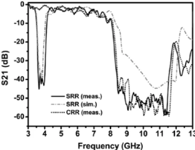
1 2 1 Frequency (GHz)FIGURE 1. Measured and simulated transmission spectra of SRR and CRR arrays
Figure 1 displays the measured and simulated transmission spectra of periodic SRRs. Two band gaps are observed throughout the frequency range of interests. First band gap is between 3.55-4.05 GHz and the second gap is from 8.15 to 11.95 GHz. The simulation results validate the experimental data as seen in the figure. In order to check the reason for the band gap formation, we proposed a test structure in which the splits are no longer present. The resulting structure is two complete rings without the splits which we name it as closed ring resonator (CRR) [4]. The splits in the split ring resonators structure play a key role in obtaining magnetic resonance. Removing the splits prevents the current from flowing between the irmer and outer rings, and therefore, the magnetic resonance is no longer present. The measured transmission data is also given in Fig. 1 with black dotted line. The first band gap is not present for
the CRR structure, however the second band gap remains. We can claim that the stop bands of spht ring resonator media carmot be assumed as a result of "negative //" behavior. Some of the observed gaps (such as the second band gap in this measurement) in the transmission spectra could also originate from the electrical response of the split ring resonators or from Bragg gaps due to periodicity. The band gap between 3.55-4.05 GHz is due to the magnetic response of split ring resonators. However, the stop band 8.15-11.95 GHz appeared due to the electrical response of the concentric rings.
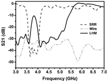
We then combined split ring resonator media with a proper thin wire media which provides the negative permittivity that is required for left-handed type of propagation [5]. Figure 2 shows the measured transmission spectra of SRR array (dashed line), wire array (dashed dotted line) and LHM array (solid hne). The wire array does not transmit EM waves at the frequency range of interest. This is due to the negative values of dielectric permittivity. The plasma frequency of wire media is at 8.0 GHz (not shown here) and below that frequency the dielectric permittivity becomes negative. One should observe a transmission band within the frequency region where both permittivity and permeability are negative. It is worthy of note that the effective plasma frequency reduces down to 5.4 GHz, when wire arrays are combined with the SRR arrays [4]. As seen in the figure, a transmission band is observed between 3.65-4.05 GHz, where the effective permeability and effective permittivity of LHM are simultaneously negative. The peak value within this transmission band is -7.6 dB. This measurement was performed for a LHM with 3 layers along the propagation direction. a • o ^ CM to 0- -10- -20- -30- -40--50. \ 1 1 k / / ^ 1 — > — r 1 J* T n^ .
\ ' /
1 i 1 I / ^ ^ ^ - * ^ - ii j^\y f IV '• ,' ' \ 1 • 1 • I • 1 r SRR Wire LHM ^'\ 1 f 1 ' 1—^— 3,0 3.5 4.0 4.5 5.0 5.5 6.0 6.5 7.0 Frequency (GHz)FIGURE 2. Measured transmission spectra of periodic SRR (dashed line), wire (dashed-dotted line) and LHM (black line) arrays.
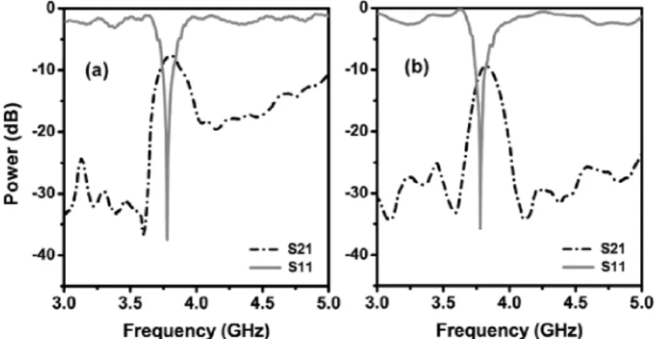
We also measured transmission from a 5 layer LHM. The result is given with dashed line in Fig. 3(b). The peak value reduces to -9.9 dB for LHM with 5 layer. The
reduction in the transmission peak could be attributed to the increased loss that is caused by the increased amount of metal and lossy substrate in the system.
We also measured reflection from 3 and 5 layered LHMs. The reflection spectra of 3 and 5 layer LHMs are shown by solid hues in Fig. 3 (a) and (b) correspondingly [7]. For both structures, we observed a dip in the reflection spectra at 3.78 GHz. The reflection is very low around -35 dB meaning that the incident EM waves do not face significant amount of reflection at the LHM surface.
-10 m T3, -20- -30--40 • / V\ -v • » / • ' "•^ S21 S11 • • 1 • -10- -20- -30-
-40-(b) I
r-' \ i
fx \'W'"'
S21 S11 3.0 3.5 4.0 4.5 5.0 3.0 3.5 4.0 4.5 5.0 Frequency (GHz) Frequency {GHz)FIGURE 3. Measured transmission (dashed line) and reflection (solid line) spectra of (a) 3 layer and (b) 5 layer two-dimensional left-handed metamaterial.
The low reflection from the surface can be attributed to either matched impedance at the interface or to the thickness resonance of the slab. Since the frequency for lowest reflection did not change for 3 and 5 layered LHMs, such behaviour could not be due to the thickness resonance. The effective parameters of the LHM structure is calculated in a recent work and impedance is fond to be matched with that of free space [7].
NEGATIVE REFRACTION
For materials with a negative refractive index, the phase velocity points toward the source that is the phase velocity and energy flow are anti-parallel inside a LHM [6]. By measuring the transmission-phases for LHMs with varying thicknesses, one can verify that the phase velocity is indeed negative. We have constmcted 4 different 2D LHM slabs with number of layers 5, 6, 7 and 8. The transmitted phases are plotted in the frequency range 3.70-4.00 GHz, which is within the left-handed transmission region. It has been recently shown that increasing the number of layers of LHM, results in a decrease at the phase of the transmitted EM wave. This is a typical left-handed behavior [6]. We measured the average phase shift between LHMs with consequent number of layers.
The index of refraction in terms of wavelength, phase shift, and change in the length of left-handed material is given by [6]:
AL ITC (1)
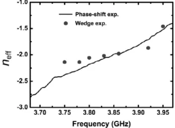
Figure 4 shows the measured refractive index values calculated by using the phase shift between the consecutive numbers of NIM layers that is reported in ref 6. The symbol (•) corresponds to the refractive indices obtained from wedge experiments at some other frequencies (data not shown here). There is a good agreement between the results obtained from two different methods.
-1.0 -3.0 Phase-shift exp. Wedge exp. 3.70 3.75 3.80 3.85 3.90 Frequency (GHz) 3.95
FIGURE 4. Measured effective refractive indices as a function of frequency that are obtained from the phase shift experiments (black hne) and prism experiments (•).
A t ^ 3 . 7 8 GHz, the wavelength of the EM wave is X=l.96 cm. The average phase shift per unit cell (AL=8.8 mm) obtained from the experimental results is A 0 = -0.51±0.047r. Inserting these values in (1), index of refraction at 3.78 GHz is found to be«eff=-2.31±0.18.
SUBWAVELENGTH IMAGING
A perfect lens is one of the most important applications of materials with a negative refractive index. The term, perfect lens, was coined by Pendry owing to the ability of such lenses to reconstruct a perfect image by recovering the evanescent components of EM waves [8]. In conventional optics, the lenses are constructed from positive-index materials and require curved surfaces to bring EM waves into focus. Positive-index lenses suffer from the diffraction limit and can only focus objects with sizes on the order of or greater than a half-wavelength.
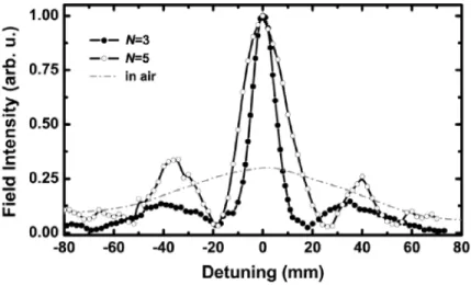
The imaging measurements are performed at 3.78 GHz, where the reflection is considerably low and the losses due to reflection are negligible. The impedance is matched at 3.78 GHz for perpendicular normal incidence; however the reflection will still affect the performance of LHM superlens for oblique incidence. In the imaging experiments, we employed monopole antermae to imitate the point source. The exposed center conductor acts as the transmitter and receiver and has a length of 4 cm {~XI2). Firstly, we measured the beam profile in free space that is plotted in Fig. 5 with a dashed hue. The full width at half maximum (FWHM) of the beam is 8.2 cm (1.03A). Then, we inserted LHM superlens, and measured the spot size of the beam as 0.13A, which is well below the diffraction hmit. The LHM superlens 3 layers along the propagation direction. The source is located ds=l.2 cm away from first boundary and the image forms (ii=0.8 cm away from second boundary of the superlens. The intensity of the electric field at the image plane is scarmed by the receiver monopole anterma with Ar = 1 mm steps.
-60 -40 -20 0 20 40
Detuning (mm)
60 80
FIGURE 5. The measured power distributions at the image plane with 3 and 5 layer LHM superlenses. Gray dashed-dotted line corresponds to the power distribution in free space. Normalized intensity in free space is multiplied with 0.3.
We also performed additional measurements in order to check the influence of the lens thickness on the resolution of the superlens. The thicker LHM superlens has higher losses due to the increased amount of lossy substrate and the metal. Thus, one would expect the resolution to decrease for a thicker superlens. We performed imaging measurements for 5 layer superlens and the beam profile at the image plane is plotted with in Fig. 5 (-o-). As seen in the figure, the resolution is decreased and the FWHM of the beam is measured as 0.25A.
CONCLUSIONS
In conclusion, we have successfully demonstrated a left-handed transmission band for 2D left-handed metamaterial in free space. Impedance matching condition is satisfied at a certain frequency regime where a sharp dip in the reflection spectra of LHMs is observed. Refractive index is calculated to be negative at the frequency region where both permittivity and permeability are negative. Phase shift and therefore phase velocity are shown to be negative. Finally, an impedance-matched, low loss negative-index metamaterial superlens is demonstrated which is capable of resolving subwavelength features with a record-level 0.13A resolution. This is the highest resolution achieved from a negative-index metamaterial superlens. Moreover, two sources separated with a distance of A/8 are clearly resolved. The effect of thickness on the subwavelength resolution is also verified, where a thicker superlens substantially reduced the resolution down to 0.25A.
ACKNOWLEDGMENTS
This work is supported by the European Union under the projects EU-NoE-METAMORPHOSE, EU-NoE-PHOREMOST, and TUBITAK under Projects Nos.
I05E066, 105A005, I06E198 and I06A017. One of the authors (E.O.) also acknowledges partial support from the Turkish Academy of Sciences.
REFERENCES
1. V. G. Veselago, Sov. Phys. Usp. 10, 509 (1968).2. D. R. Smith, W. J. Padilla, D. C. Vier, S. C. Nemat-Nasser, and S. Schultz, Phys. Rev. Lett. 84, 4184-4187(2000)
3. R. A. Shelby, D. R. Smith, and S. Schultz, Science 292, 77-79 (2001).
4. J. B. Pendry, A. J. Holden, D. J. Robbins, W. J. Stewart, IEEE Trans. Microwave Theory Tech. 47 4785 (1999).
5. K. Aydin, K. Guven, M. Kafesaki, L. Zhang, C. M. Soukoulis, and E. Ozbay, Opt Lett 29, 2623-2625 (2004).
6. K. Aydin, K. Guven, C. M. Soukoulis, and E. Ozbay, Appl. Phys Lett 86, 124102 (2005). 7. K . Aydin, 1. Bulu, and E. Ozbay, Appl. Phys Lett 90, 254102 (2007).