JournalofMaterialsProcessingTechnology235(2016)28–40
ContentslistsavailableatScienceDirect
Journal
of
Materials
Processing
Technology
j ou rn a l h o m epa ge :w w w . e l s e v i e r . c o m / l o c a t e / j m a t p r o t e c
Investigating
the
influence
of
built-up
edge
on
forces
and
surface
roughness
in
micro
scale
orthogonal
machining
of
titanium
alloy
Ti6Al4V
Samad
Nadimi
Bavil
Oliaei
a,
Yi˘git
Karpat
a,b,∗aBilkentUniversity,DepartmentofMechanicalEngineering,MicroSystemDesignandManufacturingCenter,Bilkent,Ankara,Turkey bBilkentUniversity,DepartmentofIndustrialEngineering,Bilkent,Ankara,Turkey
a
r
t
i
c
l
e
i
n
f
o
Articlehistory:
Received3November2015
Receivedinrevisedform14March2016 Accepted7April2016
Availableonline11April2016 Keywords: Cutting Micromachining Built-upedge Titaniumalloy
a
b
s
t
r
a
c
t
The edge geometry of cutting tools directly influences the chip formation mechanismin
micro-mechanicalmachining, wheretheedge radiusand uncutchip thicknessarein thesame orderof
magnitude.Anuncutchipthicknessthatissmallerthanthecuttingedgeradiusresultsinalargenegative
rakeangleduringmachining,andbuilt-upedgeformationthenaffectsthemechanicsoftheprocess.In
thisstudy,micro-scaleorthogonalcuttingtestsontitaniumalloyTi6Al4Vwereconductedto
investi-gatetheinfluenceofbuilt-upedgeformationonthemachiningforcesandsurfaceroughness.Cutting
edgesinthesetestsareengineeredusingwireEDMtechniquetohaveanedgeradiusofaround2m
andclearanceanglesof7◦and14◦.Itisobservedthatmachiningprocessinputs(uncutchipthickness,
cuttingspeed,andclearanceangle)affectthesizeofthebuilt-upedge,whichinturnaffecttheprocess
outputs.Itisobservedthatbuilt-upedgeformationprotectsthecuttingedgefromflankandcraterwear
undermicromachiningconditionsandtheinfluenceofbuilt-upedgeonthesurfaceroughnessvaries
dependingonthecuttingspeedanduncutchipthickness.Ourfindingsalsoindicateacloserelationship
betweentheminimumuncutchipthicknessandthemeanroughnessdepth(Rz)ofthemachined
sur-face.Theminimumuncutchipthicknessisfoundtobearound10%oftheedgeradiusinthepresenceof
built-upedge.
©2016ElsevierB.V.Allrightsreserved.
1. Introduction
Mechanicalmicromachiningisdefinedasthemachiningof pre-cisionpartsmadeoutofawiderangeofengineeringmaterialswith complexsurfaces(Dornfeldetal.,2006).Asolidunderstandingof themechanicsofcuttingatthemicroscaleiscrucialinbuilding predictivemodelsandcontrollingthequalityofmicroparts.A com-monlyobservedphenomenon whichappearsduringcontinuous chipformationisbuilt-upedge(BUE)anditisknowntoaffect sur-faceroughnessandtoolwear.ABUEconsistsofmateriallayers whicharedepositedontothetoolsurface,changingthetool geom-etryand,hence,themechanicsoftheprocess.AstableandthinBUE isknowntoprotectthecuttingedge(KalpakjianandSchmid,2010).
∗ Correspondingauthorat:BilkentUniversity,DepartmentofIndustrial Engineer-ing,Bilkent,Ankara,Turkey.
E-mailaddress:[email protected](Y.Karpat).
Smalluncutchipthicknessesmachinedwithtoolshavinga com-parableedgeradiuscreatessuitableconditionsforBUEformation inmicroscalemachining.Gainingabetterunderstandingofthe influenceofBUEonprocessoutputshaveresultedinanincreased interestinmachiningresearch.
Due to the micro cutting tool fabrication process and tool materialgrainsizelimitations,theedgeradiuscannot beeasily decreased withoutsacrificing thestrengthof thetool,which in turnaffectsthechipformationprocessandthesurfacequalityof themachinedworkpiece.Weuleetal.(2002)showedthe impor-tanceofedgeroundnesswhentungstencarbidemicroendmillsare usedtomachineferrousmaterials.Woonetal.(2008)studiedthe interactionbetweenuncutchipthicknessandedgeradiususing experimentaland finite element based techniques when micro machiningAISI1045.Theyshowedtheedgeradiusactinglikea negativerakeangleandfoundthataconstantstagnationpointon thetoolexistsforalargerangeofuncutchipthicknessvalues. How-ever,inanearlierstudy,Waldorfetal.(1999),studiedploughing http://dx.doi.org/10.1016/j.jmatprotec.2016.04.010
S.N.B.Oliaei,Y.Karpat/JournalofMaterialsProcessingTechnology235(2016)28–40 29
Fig.1.(a)Schematicofwire-EDMprocessingtoobtainrequiredrakeandclearanceangles,(b)Edgeradiusmeasurementoftheinsertafteredgepreparation.
Table1 Experimentalconditions. InitialCutting EdgeRadius Clearance Angle UncutChip Thickness CuttingSpeed (m/min) 1.95m 7–14 0.2–0.4–0.6–0.8–1m 30–47–62–78
modelsduringorthogonalcuttingandfoundthatastablebuilt-up modeldescribedexperimentalobservationsbetterthana stagna-tionpointmodel.Fangand Dewhurst(2005)usedsliplinefield analysistopredictthesizeofthebuilt-upedge during machin-ing.KarpatandÖzel(2008)alsopresentedasliplinefieldbased approachformachiningwithroundedgedtools,includingbuilt-up edge.Karpat(2009)consideredtheinfluenceofcuttingedgeradius includingbuilt-upedgeduringmicroscalemachiningandstudied theeffectoffractureonmachiningoutputs.Childs(2013) devel-opeda finiteelementmodeltopredictbuilt-upedgeformation duringmachiningofsteelbyintegratingadamagemodel.Some preliminaryresultsonsimulatingbuilt-upedgeduringmicroscale machiningwerealsopresentedinChilds(2013).Adetailed inves-tigationofhowbuilt-upedgeinfluencesmicroscalemachiningis theaimofthisstudy.
Table2
EDXanalysisofsurfaceonthetool.
InsertSurface beforemachining
AnalysisofBUE InsertSurface
afterCleaning Co%5.19 Al%5.66 Co%4.65 W%94.81 Ti%82.82 W%93.95 V%3.46 Co%0.59 W%7.48
Inmicroscalemachining,thecuttingtooledgeradiusandthe amountofmaterialbeingcutareinthesameorderofmagnitude. Thereisavalueofuncutchipthicknessafterwhichcontinuouschip formationceases.Thiscriticalvalueisdefinedasminimumchip thickness,whichisknowntobeafunctionofthetoolmaterial, cuttingedgeradius,andworkpiecematerial(Ikawaetal.,1992). Luccaetal.(1991,1993)indicatedtheimportanceoftheslidingand ploughingatthetoolworkpieceinterfaceduetoedgeradiusofthe toolduringultraprecisionmachiningconditions.Kimetal.(2004) analyzedtheperiodicityofforcesduringmicromillingand identi-fiedthetransitionbetweennon-cuttingandcuttingregimesnear
30 S.N.B.Oliaei,Y.Karpat/JournalofMaterialsProcessingTechnology235(2016)28–40
Fig.2.InvestigationofthetoolsurfaceafterwireEDM(a)SEMimage,(b)Surfacetopographyoftherakeface.
theminimumchipthicknessvalue.Theyconcludedthatthe peri-odicityofcuttingforcesisaffectedbytheminimumchipthickness, feedpertooth,andcuttingpositionangle.Theyobservedalocal maximuminthethrustforcesthattakesplacearoundminimum chipthicknessvalue.Junetal.(2006)investigatedthedynamicsof microendmillingandobservedpeaksinthethrustforcearound minimumchipthicknessduringmicromachiningof ferriteand pearlite.Theyconcludedthattheminimumchipthicknesseffect causesinstabilityatlowfeedrates.Thesamephenomenonwas observedbyLiuetal.(2004)andnamedasfeedrateinstability.Son etal.(2005)studiedminimumuncutchipthicknessandits rela-tiontotheedgeradiusduringdiamondturningofvariousmaterials. Theydevelopedarelationshipbetweenminimumuncutchip thick-ness,frictionangle,andedgeradius.Malekianetal.(2012)used aminimumenergybasedmethodtomodelminimumuncutchip thicknesswhilemachiningaluminumalloy.Theyfoundthe stagna-tionpointtobeapproximately23%oftheedgeradius,anditisnot aconstantpointbutaregiononthetool.CubaRamosetal.(2012) emphasizedtheimportanceofbuilt-upedgeformationduring tran-sitionfromploughingtocuttingduringmicroscalemachiningof AISI1045anddevelopedanewmodelfortheestimationof
mini-mumchipthickness.Inthisstudy,minimumuncutchipthickness phenomenoninthepresenceofBUEisinvestigatedbyfocusingon theinteractionbetweenBUEandsurfaceroughness.
Duetoitshighreactivitywithcuttingtool materialsandits lowthermalconductivity,titaniumalloysareconsidered difficult-to-cut,sorapid toolwearisan importantissuethataffectsthe qualityofthemachinedproducts.BUEformationduring machin-ingoftitaniumundermacroscalemachiningconditionshasbeen wellstudiedinliterature.TheissuesrelatedtoBUEandtoolwear havebeensummarized inEzugwuand Wang(1997),Armendia etal.(2010)andPramanikandLittlefair(2015).Thepsonthiand Özel(2015)studiedmicromillingoftitaniumalloyTi6AL4Vand observedBUEwhencuttingedgeisworn.Thewearmechanisms oftitaniumalloyswereshown tobequitedifferentfromsteels and nickel alloys inHartung and Kramer(1982). It wasshown thattoolwearwasgreatlyreducedwhenadhesionoccursbetween toolandchip.Theadhesionlayerpreventsslidingattheinterface andimprovestoollifeundercertainconditions.Inarecentstudy, Kümmeletal.(2014)showedthattoolwearperformancemaybe improvedwhencuttingtoolswithintentionalbuilt-upedgeare employedinmachining.Kümmeletal.(2015)usedlasersurface
S.N.B.Oliaei,Y.Karpat/JournalofMaterialsProcessingTechnology235(2016)28–40 31
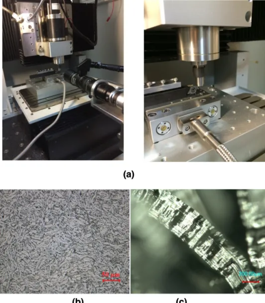
Fig.3.(a)Theexperimentalsetupformicroorthogonalexperiments,(b)Microstructureofthetitaniumworkpieceusedinthisstudy,(c)Atypicalchipproducedduring micromachiningexperiments.
texturingtocreatedifferentdimplestructuresandchannelsonthe rakefaceofthetool.ThedimpletexturesareshowntoincreaseBUE adhesiononthetool.Inthisstudy,electricaldischargemachining (EDM)techniqueisusedtopreparethecuttingedges.UsingEDM processcreatesmicroscalecratersonthesurfaceofthetool,which mayalsopromoteBUEadhesionduringmachining.
Inthisstudy,theinfluenceofbuilt-upedgeonprocessforces, surfacequalityandminimumchipthicknessduringmicro machin-ingoftitaniumalloyhasbeeninvestigatedindetail.Cuttingedges withsmalledgeradiiwerespecificallyfabricatedanduncutchip thicknessvaluesweresettobelessthantheedgeradiusto cre-atemicroscalemachiningconditions.Cuttingedgesandmachined surfaceswereinvestigatedaftertheteststorevealtheinfluenceof built-upedgeonprocessoutputs.
2. Experimentalprocedure
2.1. Fabricationofcuttingedgemicrogeometry
Thecuttingedgemicrogeometryisobtainedthroughmicrowire electricdischargemachining(wireEDM)technique.TheEDM tech-niqueisadvantageousintermsofcontrollingthemicrogeometry oftheedge.ThefeasibilityofedgepreparationusingEDM
tech-niquewasshownbyYussefianetal.(2010).Inthisstudy,theedge geometriesoftheuncoatedcarbidetools(DCMW11T304H13A) with0◦rakeanglearemodifiedbyusingthewireEDMdevice (Sod-ickAP250L).TheUandVaxesofthewireEDMmachineareutilized toobtainnecessaryclearance(relief)anglesonthecuttingedges asshowninFig.1a.AnEDMwirediameterof100mwasused. ThewireEDMmachineusesoilasdielectricfluidinordertoobtain superiorsurfacequality.Cuttingedgeswithtwodifferentclearance angles(7◦ and14◦)werepreparedandedgeradiiofeachinsert weremeasured.Fig.1bshowstheprofileofacuttingedgebefore andafteredgepreparationwithEDMmachining.
Alaserscanningmicroscope(KeyenceVK-X100)wasusedto measuretheedgeradiusandclearanceangleofthetools.Theedge radiusafterEDMmachiningis measuredas1.95mwhere the initialedgeradiusoftheinsertwas25m.Adetaileddiscussion ontheinfluenceofedgeradiusonmachiningandthe uncertain-tiesrelatedtoitsmeasurementsweredescribedinDenkenaand Biermann(2014).Scanningelectronmicroscopeimageofthetool surfaceafterwireEDMisshowninFig.2a.Thesurfaceroughness (Ra)oftheinsertwasmeasuredas0.11musingalaserscanning
32 S.N.B.Oliaei,Y.Karpat/JournalofMaterialsProcessingTechnology235(2016)28–40
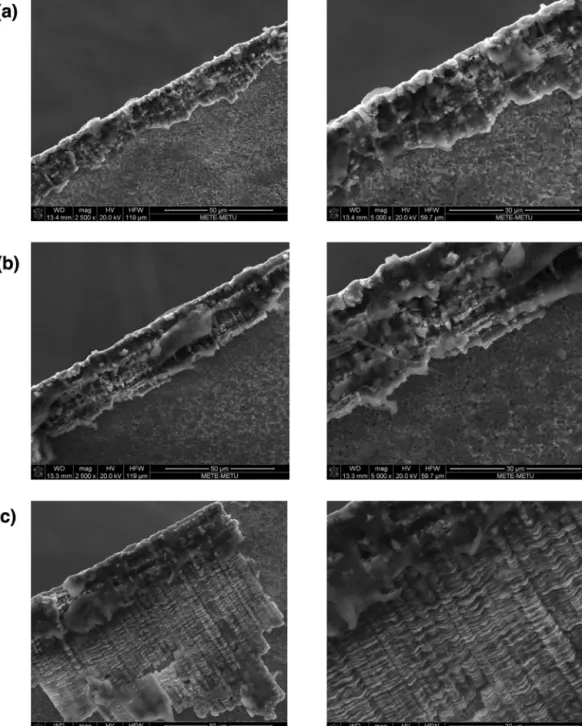
Fig.4.SEMimagesofthecuttingedgesaftermachiningtests:a)0.2m,b)0.4m,c)0.6m.
2.2. Experimentalsetupfororthogonalmicrocuttingtests
Athree-axishybridmicromachiningcenter(MikrotoolsDT110), capable of performing micro turning processes, was used to conductmicro orthogonal cuttingexperiments. The machine is equipped with a spindle with maximum rotational speed of 3000rpm.Titaniumalloyshaftswith10mmouterdiameterand 0.25–0.35mmwallthicknesswereprepared.Onlyoneendofthe shaftwasmachinedtobehollow.Thedepthofhollowsidewaskept at3–4mm.InsertswithengineerededgeswereplacedonaSDACR 1212K11Stoolholder,whichwasthenattachedtotheKistlermini dynamometer(9256,max250N)asshowninFig.3.Micro machin-ingforcesweremeasuredandtransferredtoaPCthroughadata acquisitioncard(NationalInstrumentsPXI series).Thetitanium alloyTi6Al4V(␣+)workmaterialwithlamellarmicrostructure
(grainsof average25m lengthand 5m thickness), which is showntobesuitableformicromachiningapplicationsinAttanasio etal.(2013),wasusedinexperiments(Fig.3b).Ithadahardnessof 328HV.Theworkpiecewasfedtowardsthecuttingtoolwith nec-essaryfeedratetoobtaintherequireduncutchipthicknessduring orthogonaltests.Themachiningtimeanddistancewerechecked usingahighspeedmicroscopetomakesurethatthedesiredfeed ratewasachievedduringtests.Fig.3cshowsatypicalcontinuous chipproducedduringmicromachiningexperiments.
Inthis study,micro scaleorthogonalmachiningexperiments ontitaniumalloyTi6Al4Vwereperformedbyusingcuttingedges specificallyproducedforthatpurpose.Adifferentcuttingedgewas usedineachtest.Cuttingtoolshaveclearanceanglesof7and14◦. Thereasonforusingalowclearanceangleistochangemachining conditionsinthecuttingzoneandobserveitsinfluenceonthe
pro-S.N.B.Oliaei,Y.Karpat/JournalofMaterialsProcessingTechnology235(2016)28–40 33
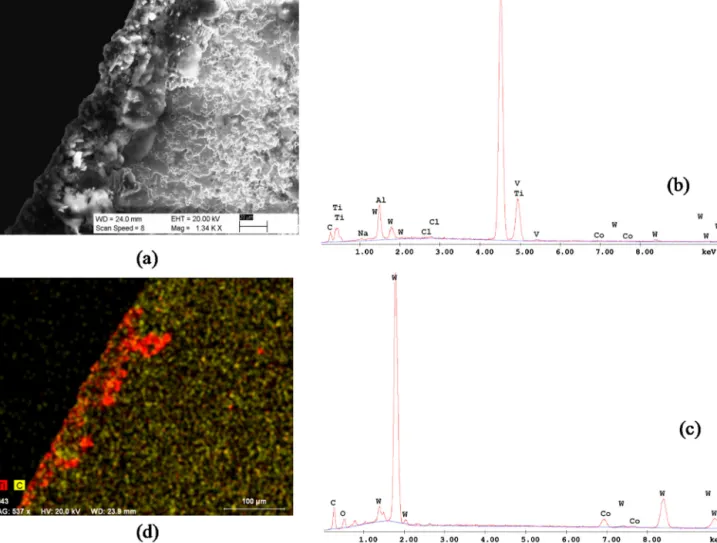
Fig.5. (a)ScanningelectronmicroscopeimageoftheBUEregionandcorrespondingEDXmap,(b)EDXspectrumanalysisofthebuiltupedgezoneontherakeface,(c)EDX spectrumanalysisofthetoolsurface,(d)ColormapoftheTiandCelementsontheBUE.
34 S.N.B.Oliaei,Y.Karpat/JournalofMaterialsProcessingTechnology235(2016)28–40
Fig.7. 3DEdgeprofilemeasurements.Leftcolumn7◦,rightcolumn14◦clearanceangle.Uncutchipthicknessfromtoptobottom0.4,0.6,0.8,and1m.Cuttingspeedis
S.N.B.Oliaei,Y.Karpat/JournalofMaterialsProcessingTechnology235(2016)28–40 35
Fig.8.IncreasingBUEtiplengthwithincreasinguncutchipthicknessa)0.4,b)0.6,c)0.8,and,d)1m.
36 S.N.B.Oliaei,Y.Karpat/JournalofMaterialsProcessingTechnology235(2016)28–40
Fig.10. (a)2Dedgeprofilecorrespondingto14◦clearanceangleat0.4muncutchipthicknessafter2minofcontinuousmachining,(b)TiplengthofBUEafter9minof
continuousmachining(62m/mincuttingspeed).
cessoutputssuchasbuiltupedgeformationandsurfaceroughness. Arangeofcuttingspeedvalueswasconsidered,setat30,47,62, and78m/minbasedonpracticalmachiningconditionsoftitanium alloyTi6Al4Vwithinthelimitsofthespindle.Uncutchip thick-nessvalueswereconsideredas0.2,0.4,0.6,0.8and1m,which areallsmallerthantheedgeradius.Experimentalconditionsare summarizedinTable1.Theforcesduringmicromachiningwere alsomeasured.Theexperimentswereconductedover12sforeach cuttingconditionduringforcemeasurementstudies.
3. InvestigationofBUEaftermicromachiningexperiments Experimentswereperformedateachconditionandthecutting edgesoftheinsertsareinvestigatedaftereachexperiment.Fig.4 showsthescanningelectronmicroscopeimageoftherakefaceof thecuttingedgewherethebuilt-upedgeformationcanbeclearly seen.
ArelativelylargeBUElength(around20–100m),compared totheuncutchipthicknessisobserved.Basedontheseimages, thethicknessoftheBUEislargeratthetipofthetooland grad-uallydecreasesonthetoolrakeface.HartungandKramer(1992) observedbuiltuplayer(BUL)andbuiltupedge(BUE)formation whilemacroscalemachiningtitaniumalloyTi6Al4Vwithdifferent cuttingtoolmaterials.Theyobservedthattoolwearisconsiderably reducedatcertainconditionsasalayerpreventsrelativeslidingat thetoolchipinterfaceandlimitsthediffusionrateofthetool con-stituents.Athighspeeds,thisprotectivelayerisremovedandtool wearincreasesquickly.Thethicknessofthislayerisdetermined bythebalancebetweentherateofdiffusionofthetoolmaterial throughit,andtherateofdissolutionofthereactionlayerinthe workmaterial.Theyobservedtheabsenceofcobaltandalayerof TiCwasformedonthetoolsurfacewhichwasreplenishedbythe carbonatomsremovedfromtheWCgrainsbelow.Similar observa-tionswerealsomadebyIkutaetal.(2002),Armendiaetal.(2010), Gerezetal.(2009)andArrazolaetal.(2009)underconventional
machiningcaseswhereelevatedtemperatures(700–800◦C)exist atthetoolchipinterface.Atmicroscalemachiningthetemperature riseatthetool-chipinterfaceisexpectedtobelowercomparedto macroscalemachiningconditions.
Inordertoinvestigatethechemicalcompositionofthetooland BUE,anEDXanalysiswasperformedandtheresultsareshownin Fig.5.AscanningelectronmicroscopeimageoftheBUEregioncan beseeninFig.5a.Titanium,aluminum,andvanadiumelements inthebuilt-upedgeregioncanbeclearlyidentifiedasshownin Fig.5banditsdetailedchemicalcompositionisgivenTable2.The EDXanalysisofthetoolsurfacebeforemachiningisalsoshownin Fig.5canditschemicalcompositionisalsogiveninTable2.Acolor mapofTiandCelementsontheBUEandtoolsurfacesareshownin Fig.5d.TheEDXanalysiswasperformedforalluncutchipthickness valuesandsimilarresultsareobserved.
InordertoinvestigatetheinfluenceofBUE onthetool-chip interface,thesectionof thetool under theBUE isalso investi-gatedaftercleaningit usinganultrasonicprocess.EDXanalysis wasrepeatedontheregionwhereBUEexisted.Fig.6showsthe EDXspectrumofthetoolsurfacewhereCo(%4.65)andW(%93.95) wasdetected.TheamountofCoisslightlylowercomparedtothe originaltoolsurface(seeTable2).Thisisinaccordancewiththe observationsofHartungandKramer(1982),althoughthe differ-enceisquitelow.
Fig.7showstheedgeprofilesobtainedthroughalaserscanning microscopewhereshapesofbuilt-upedgeforeachcuttingcasecan beseen.Fig.8showstheopticalmicroscopeimagestakenfromthe flankfaceofthecuttingedges.
Fig.9showsedgeprofilesofcuttingedgeswheretheshapeof thebuiltupedgearoundthetooltipcanbeseen.Basedonthese images,asuncutchipthicknessincreases,theaveragetiplengthof BUEincreases(fromaround10mto19minFig.8).Thelength ofBUEontherakefaceislongeratloweruncutchipthickness. NosignificantdifferenceintermsofBUEsizewasobserveddueto differentclearanceangles.
S.N.B.Oliaei,Y.Karpat/JournalofMaterialsProcessingTechnology235(2016)28–40 37
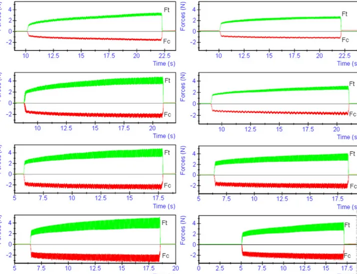
Fig.11.Forcevs,timemeasurements.Leftcolumn7◦,rightcolumn14◦clearanceangle.Uncutchipthicknessfromtoptobottom0.4,0.6,0.8,and1m.
Fig.10ashowstheedgeprofileofthetoolafter12sof contin-uousmachiningaftercleaningoftheBUE.Nosignofcraterand flankwearwasobserved,confirmingtheprotectiveeffectofBUE. However,theedgeprofilemeasurementrevealedthatedgeradius increasedto3–4mattheendofthemachiningtest.Edge round-ingisaknownformoftoolwearduringmicroscalemachining.The machiningprocesswasfurtherlengthenedto2and9minof contin-uousmachining.Theedgeradiuswasalsomeasuredtobearound 3–4mandagainnosignofflank/craterwearwasobservedonthe tool.Fig.10bshowsthetiplengthofBUEafter9minofmachining fromflanksideofthetool.
Theincreaseinedgeradiusmayhavehappenedduring burn-inperiodofthetool,anditfurtherpromotestheaccumulationof materialinfrontofthetool.TheinfluenceofBUEonmachining forcesandsurfacequalityareinvestigatedinthenextsection. 4. Forcemeasurementsduringmicroscalemachiningof titaniumalloyTi6AL4V
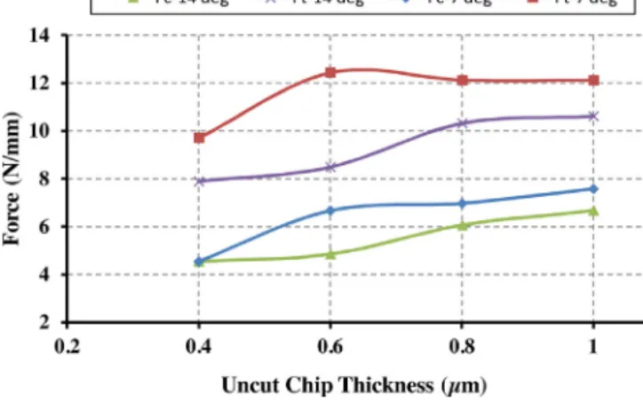
Measuringforcesduringmicromachiningtestsallowsthe inves-tigationoftheprocessforces inthepresence ofBUEformation. Fig.11 shows theforcemeasurementsobtainedfor 7◦ and 14◦ clearanceangletoolsfordifferentuncutchipthicknessvaluesat 62m/mincorrespondingto12sofcutting.Thesemeasurements correspondtothecuttingedgeimagesshowninFig.7.Each
orthog-onalcuttingexperimentwasrepeatedat leastthree timeswith upsharptools,andconsistentresultswereobtained.Themeasured forceswerefilteredwithalowpassfilterandaveragemachining forcesandforcevariationsaroundaverageforceswerecalculated. Machiningforceswereobservedtoincreaseattheinitialstages ofmachining,indicatingchangingcontactconditionsatthetooltip andBUEformationontherakeface.Increasingaverageforcemay berelatedtoedgeroundingandincreasingforcevariationsmaybe relatedtoBUEformation.Thethrustforce(Ft)seemstobeaffected
bytheBUEmorethanthecuttingforce(Fc).Forcemeasurements
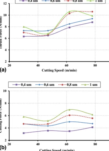
followasteadytrendindicatingtheformationofastableBUE. Fig.12showstheinfluenceofcuttingspeedonthrustand cut-tingforcesfordifferentuncutchipthicknessvalues.Thrustforces increasewithincreasingcuttingspeedfor0.4-0.6muncutchip thickness.Thereisasignificantjumpinthrustforcesat62m/min for uncut chip thicknesses of 0.8–1m. These resultsindicate theinfluenceofincreasingbuilt-upedgetiplengthwith increas-inguncut chipthickness andcuttingspeed. Ascuttingspeed is increasedto78m/min,thrustforcesplateau,whichmaybedue tosharptipofBUE.Cuttingforcesmostlypeakedaround62m/min andtendtodecreaseat78m/min.
Fig.13showstheaveragecuttingandthrustforcesasafunction ofuncutchipthicknessforcuttingedgeswith7◦and14◦clearance angles.AlthoughnocleardifferenceinBUEshapeswasobserved between7and14clearanceangles,forcemeasurementsincreaseas
38 S.N.B.Oliaei,Y.Karpat/JournalofMaterialsProcessingTechnology235(2016)28–40
Fig.12.Meanvaluesof(a)thrustand(b)cuttingforcesasafunctionofcuttingspeed.
clearanceangledecreasesasexpected.Cuttingforcemeasurements increasewithincreasinguncutchipthickness.Thrustforce mea-surementsfor7◦clearanceangleexhibitapeakat0.6mandthen plateaubetween0.8and1m.Thrustforcemeasurementfor14◦ clearanceangletoolexhibitedasimilartrend,howeveritplateaus between0.8and1muncutchipthickness.Thepresenceofa built-upedgeisknowntobeimportantsincealargecontactareawiththe workpieceandthetoolexistsasaresultofBUE.Therefore,larger thrustforcesareobtainedinthemeasurements.
5. EffectofBUEonsurfaceroughness
Inmicro scalemachining,theinfluence ofmachining condi-tionsonthesurface roughness is quiteimportant as shown in CubaRamosetal.(2012).Thissectioninvestigatestheinfluence ofBUEonsurfacequality. Asmentioned earlier,theuncutchip thicknesswherethethrustforcereachesitspeakvalueis identi-fiedasminimumchipthicknesswhichdefinesthetransitionfroma shearing-dominatedtoaploughing-dominatedmachiningregion. Inpreviousstudies,theinfluenceofthesurfaceroughnessbeing cutisusuallyneglected.Inthisstudy,aftereachtest,themachined surfacesare investigated by using a laser scanning microscope (KeyenceVK-X100) for contactlesssurface roughness measure-mentswhere arithmeticmeanheight(Ra)and averagedistance betweenthehighestpeakandlowestvalley(Rz)valuesare consid-eredtostudytheeffectofbuilt-upedgeonsurfaceroughness.In measurements,imagestitchingcapabilityofthelasermicroscope isusedtoinvestigatealargeareafordetailedsurface characteriza-tion.Noisefilteringandplanartiltcorrectionisappliedtoaregion ofinterestof(750m×200m)beforeextractingRaandRz
val-ues.Acut-off(c)valueof80mwasusedtoremovetheinfluence ofwavinessfromsurfaceroughnessmeasurements.Fig.14shows surfacetopologiesaftermachiningat62m/minat0.4and1m uncutchipthicknesses.Theridgesonthemachinedsurfacedueto nonuniformBUEtipformationcanbeclearlyseen.
Fig.15showsthesurfaceroughnessmeasurementsasafunction ofspeedforvariousuncutchipthicknessvalues.Itisinterestingto seethatsurfaceroughness(Rz)valuesimprovearound62m/min cuttingspeed,correspondingwithhighcuttingand thrustforce values(Fig.12).After62m/mincuttingspeed, thesurface qual-ity deteriorates significantly mainly due to scratching effect of BUE.Theresultsindicatethatthereexistsacomplexrelationship betweenuncutchipthickness,cuttingspeed,BUEformation,and surfaceroughness.Relativelybettersurfacequality valueswere obtainedatloweruncutchipthicknessvalues.
InFig.15,at0.2muncutchipthickness,averagesurface rough-ness(Rz)valueof0.13mwasmeasured.Asfor0.4muncutchip
thickness,averagesurfaceroughness(Rz)valueof 0.16m was
measured.ItmustbenotedthattheRzanduncutchipthickness valuesarequiteclosetoeachother.Inordertoobservethechip formationduringmicroscalemachining,ahighspeedmicroscope (KeyenceVW9000series)isused.Duetolimitationsofthehigh speedmicroscope,therecordingwasonlymadefromthebackside ofthechip.Basedonthevideorecordings,under0.4muncutchip thicknessvalue,thechipformationtransitionedfromcontinuous todiscontinuous.Themediafilesattachedtotheonlineversion ofthepaperclearlyshowcontinuous(Video1for0.8muncut chipthickness)andintermittent(Video2for0.2muncutchip thickness)machiningcycles.Itmustbenotedthatinthe experi-mentalsetupusedinthisstudy,theworkpieceiscontinuouslyfed
S.N.B.Oliaei,Y.Karpat/JournalofMaterialsProcessingTechnology235(2016)28–40 39
towardsthecuttingedge.Therefore,intermittentchipformation isexpectedwhenuncutchipthicknessislessthanminimumchip thickness.Basedonthesefindings,thetransitionfromcontinuous tointermittentchipformationhappensaround0.4m.Assuming thatedgeradiusis4m,theminimumuncutchipthicknessin thepresenceofBUEisaround10%oftheedgeradius.Thisratio issmallerthanthosereportedforstagnationpointassumptionin literature.
6. Conclusions
Thisstudyinvestigatestheinfluenceofbuilt-upedgeontool wear,forces,andsurfaceroughnessundermicroscalemachining conditions.Theuncutchipthickness,cuttingspeed,andclearance angleareconsideredasprocessvariables.Basedonourfindings: • AstableBUEformationexistsundermicroscalemachining
con-ditionsofthetitaniumalloyTi6Al4Vconsideredinthisstudy. • Duringbreak-inperiod,thecuttingedgeradiusincreaseswhich
promotesBUEformation,protectingthetoolsfromcraterand flankwear.EDXanalysisoftheinsertsurfaceindicatedasmall changeinthechemical analysisofthesurface.Butitisnotas significantasthoseinmacroscalemachiningprocesses. • Machininginputconditionsareshowntoaffectthesizeandshape
ofBUE,whichaffectmachiningforcesandsurfaceroughness val-ues.Acuttingspeed of62m/minresultedinlargerforcesand bettersurfaceroughnessvalues.
Fig.13.Meanvaluesofcuttingandthrustforcesat62m/mincuttingspeedfor cuttingedges.
• Ourfindingsconfirmtheinfluenceofsurfaceroughnesson min-imumuncutthickness.InthepresenceofBUE,theratioofuncut chipthicknesstoedgeradiusiscalculatedtobearound10%.
Acknowledgements
The authorswould like tothank The Scientific and Techno-logicalResearchCouncilofTurkey(TÜB˙ITAK-110M660,National
Fig.14.Lasertopographyimagesofthesurfacesmachinedat62m/mincuttingspeedata)0.4muncutchipthickness,b)1muncutchipthickness,c)0.8muncutchip thicknessat78m/min(with300×heightmagnification).
40 S.N.B.Oliaei,Y.Karpat/JournalofMaterialsProcessingTechnology235(2016)28–40
Fig.15.Surfaceroughnessanalysisasafunctionofcuttingspeed(a)Ra,(b)Rz.
YoungResearcherCareerDevelopmentProgram)andState Plan-ningOrganization of Turkey (HAMIT-Micro System Design and ManufacturingResearchCenter).
AppendixA. Supplementarydata
Supplementarydataassociatedwiththisarticlecanbefound,in theonlineversion,athttp://dx.doi.org/10.1016/j.jmatprotec.2016. 04.010.
References
Armendia,M.,Garay,A.,Iriarte,L.M.,Arrazola,P.J.,2010.Comparisonofthe machinabilitiesofTi6Al4VandTIMETAL54MusinguncoatedWCCotools.J. Mater.Process.Technol.210,197–203.
Arrazola,P.J.,Garay,A.,Iriarte,L.M.,Armendia,M.,Marya,S.,LeMaitre,F.,2009.
Machinabilityoftitaniumalloys(Ti6AlVandTi555.3).J.Mater.Process. Technol.209,2223–2230.
Attanasio,A.,MarcelloGelfi,M.,Pola,A.,Ceretti,E.,Giardini,C.,2013.Influenceof materialmicrostructuresinmicromillingofTi6Al4Valloy.Materials6, 4268–4283,http://dx.doi.org/10.3390/ma6094268.
Childs,T.H.C.,2013.Ductileshearfailuredamagemodellingandpredicting built-upedgeinsteelmachining.J.Mater.Process.Technol.213,1954–1969.
CubaRamos,A.,Autenrieth,H.,Straußa,T.,Deuchert,M.,Hoffmeister,J.,Schulze, V.,2012.Characterizationofthetransitionfromploughingtocuttinginmicro machiningandevaluationoftheminimumthicknessofcut.J.Mater.Process. Technol.212,594–600.
Denkena,B.,Biermann,D.,2014.Cuttingedgegeometries.CIRPAnn.—Manuf. Technol.63,631–653.
Dornfeld,D.,Min,S.,Takeuchi,Y.,2006.Recentadvancesinmechanical micromachining.CIRPAnn.—Manuf.Technol.55(2),745–768.
Ezugwu,E.O.,Wang,Z.M.,1997.Titaniumalloysandtheirmachinability—areview. J.Mater.Process.Technol.68,262–274.
Fang,N.,Dewhurst,P.,2005.Slip-linemodelingofbuilt-upedgeformationin machining.Int.J.Mech.Sci.47,1079–1098.
Gerez,J.M.,Sanchez-Carrilero,M.,Salguero,J.,Batista,M.,Marcos,M.,2009.ASEM andEDSbasedstudyofthemicrostructuralmodificationsofturninginsertsin thedrymachiningofTi6Al4VAlloy.AIPConf.Proc.1181,567–574.
Hartung,P.D.,Kramer,B.M.,1982.Toolwearintitaniummachining.Ann.CIRP32, 75–80.
Ikawa,N.,Shimada,S.,Tanaka,H.,1992.Minimumthicknessofcutin micromachining.Nanotechnology3,6–9.
Ikuta,A.,Shinozaki,K.,Masuda,H.,Tamame,Y.,Kuroki,H.,Fukaya,Y.,2002.
ConsiderationoftheadhesionmechanismofTialloysusingcementedcarbide duringthecuttingprocess.J.Mater.Process.Technol.127,251–255.
Jun,M.B.G.,DeVor,R.E.,Kapoor,S.G.,Liu,X.,2006.Investigationofthedynamicsof microendmilling—partII:modelvalidationandinterpretation.J.Manuf.Sci. Eng.128(4),901–912.
Kümmel,J.,Gibmeier,J.,Müller,E.,Schneider,R.,Schulze,V.,Wanner,A.,2014.
Detailedanalysisofmicrostructureofintentionallyformedbuilt-upedgesfor improvingwearbehaviourindrymetalcuttingprocessofsteel.Wear311, 21–30.
Kümmel,J.,Braun,D.,Gibmeier,J.,Schneider,J.,Greiner,C.,Schulze,V.,Wanner,A., 2015.Studyonmicrotexturingofuncoatedcementedcarbidecuttingtoolsfor wearimprovementandbuilt-upedgestabilisation.J.Mater.Process.Technol. 215,62–70.
Kalpakjian,S.,Schmid,S.,2010.ManufacturingEngineeringandTechnology,6th ed.PrencticeHall,Singapore,pp.563–564.
Karpat,Y.,Özel,T.,2008.Mechanicsofhighspeedcuttingwithcurvilinearedge tools.Int.J.Mach.ToolsManuf.48,195–208.
Karpat,Y.,2009.Investigationoftheeffectofcuttingtooledgeradiusonmaterial separationduetoductilefractureinmachining.Int.J.Mech.Sci.51(7), 541–546.
Kim,C.,Mayor,J.R.,Ni,J.,2004.Astaticmodelofchipformationinmicroscale milling.J.Manuf.Sci.Eng.126(4),710–718.
Liu,X.,DeVor,R.E.,Kapoor,S.G.,Ehmann,K.F.,2004.Themechanicsofmachining atthemicroscale:assessmentofthecurrentstateofthescience.J.Manuf.Sci. Eng.126(4),666–678.
Lucca,D.A.,Rhorer,R.L.,Komanduri,R.,1991.Energydissipationinthe ultraprecisionmachiningofcopper.Ann.CIRP40,69–72.
Lucca,D.A.,Rhorer,R.L.,Komanduri,R.,1993.Effectoftooledgegeometryon energydissipationinultraprecisionmachining.Ann.CIRP42,83–86.
Malekian,M.,Mostofa,M.G.,Park,S.S.,Jun,M.B.G.,2012.Modelingofminimum uncutchipthicknessinmicromachiningofaluminum.J.Mater.Process. Technol.212,553–559.
Pramanik,A.,Littlefair,G.,2015.Machiningoftitaniumalloy(Ti-6Al-4V)—theory toapplication.Mach.Sci.Technol.:Int.J.19,1–49,http://dx.doi.org/10.1080/ 10910344.2014.991031.
Son,S.M.,Lim,H.S.,Ahn,J.H.,2005.Effectsofthefrictioncoefficientonthe minimumcuttingthicknessinmicrocutting.Int.J.Mach.ToolsManuf.45, 529–535.
Thepsonthi,T.,Özel,T.,2015.3-Dfiniteelementprocesssimulationofmicro-end millingTi-6Al-4Vtitaniumalloy:experimentalvalidationsonchipflowand toolwear.J.Mater.Process.Technol.221,128–145.
Waldorf,D.J.,DeVor,R.E.,Kapoor,S.G.,1999.Anevaluationofploughingmodelsfor orthogonalmachining.J.Manuf.Sci.Eng.121,550–558.
Weule,H.,Huntrupl,V.,Tritschlerl,H.,2002.Microcuttingofsteeltomeetnew requirementsinminiaturization.CIRPAnn.—Manuf.Technol.50,61–64.
Woon,K.S.,Rahman,M.,Neo,K.,Liu,S.,2008.Theeffectoftooledgeradiusonthe contactphenomenonoftool-basedmicromachining.Int.J.Mach.ToolsManuf. 48(12–13),1395–1407.
Yussefian,N.Z.,Koshy,P.,Buchholz,S.,Klocke,F.,2010.Electro-erosionedge honingofcuttingtools.CIRPAnn.−Manuf.Technology59,215–218.