Photonic crystal-based resonant antenna with a very high directivity
B. Temelkuran, Mehmet Bayindir, E. Ozbay, R. Biswas, M. M. Sigalas et al.
Citation: J. Appl. Phys. 87, 603 (2000); doi: 10.1063/1.371905 View online: http://dx.doi.org/10.1063/1.371905
View Table of Contents: http://jap.aip.org/resource/1/JAPIAU/v87/i1
Published by the American Institute of Physics.
Additional information on J. Appl. Phys.
Journal Homepage: http://jap.aip.org/
Journal Information: http://jap.aip.org/about/about_the_journal
Top downloads: http://jap.aip.org/features/most_downloaded
Information for Authors: http://jap.aip.org/authors
COMMUNICATIONS
Photonic crystal-based resonant antenna with a very high directivity
B. Temelkuran,a)Mehmet Bayindir, and E. OzbayDepartment of Physics, Bilkent University, Bilkent, Ankara, 06533, Turkey R. Biswas, M. M. Sigalas, G. Tuttle, and K. M. Ho
Ames Laboratory and Microelectronics Research Center, Iowa State University, Ames, Iowa 50011 共Received 20 May 1999; accepted for publication 24 September 1999兲
We investigate the radiation properties of an antenna that was formed by a hybrid combination of a monopole radiation source and a cavity built around a dielectric layer-by-layer three-dimensional photonic crystal. We measured a maximum directivity of 310, and a power enhancement of 180 at the resonant frequency of the cavity. We observed that the antenna has a narrow bandwidth determined by the cavity, where the resonant frequency can be tuned within the band gap of the photonic crystal. The measured radiation patterns agree well with our theoretical results. © 2000
American Institute of Physics. 关S0021-8979共00兲03601-X兴
Photonic crystals, in which electromagnetic共EM兲 wave propagation is forbidden in all directions for a certain range of frequencies, have a wide range of applications extending from microwave to optical frequencies.1–3However, the fab-rication of photonic crystals at optical frequencies was a ma-jor challenge since the invention of these materials nearly a decade ago. Recently, a photonic crystal with a full three-dimensional 共3D兲 band gap at 1.55m wavelength was re-ported by Fleming and Lin.4In addition to this major break-through, the same structure was previously fabricated at millimeter wave and microwave frequencies,5,6 where a number of photonic crystal based applications were demonstrated.7 Among these applications, there is a great deal of growing interest for photonic crystal-based antennas.8,9 The reported experimental and theoretical stud-ies on the antenna applications mostly made use of the total reflection property of photonic crystals. The antennas mounted on photonic crystal substrate surfaces exhibited high efficiency and directivity compared to conventional an-tennas on dielectric substrates.10 Although high directivities which could be achieved using array antennas on photonic crystals were suggested,11the maximum directivity that was demonstrated by Brown and McMahon using a photonic crystal-based single dipole antenna was 10, along with a ra-diative gain of 8.10
One other important property of photonic crystals is that by breaking the periodicity of the crystal, one can create resonant cavities. Resonant cavity enhanced detectors12 and waveguide applications13 were recently demonstrated using localized modes of the cavities built around photonic crys-tals. In this letter, we report a photonic crystal-based reso-nant antenna with a very high directivity and gain. The
an-tenna was formed by a hybrid combination of a monopole radiation source and a cavity built around a dielectric 3D layer-by-layer photonic crystal.
The layer-by-layer dielectric photonic crystal we used in our experiments was designed to have a three-dimensional band gap with a midgap frequency around 12 GHz.13 We used the output port of a microwave network analyzer and a monopole antenna to obtain EM waves. The monopole an-tenna was constructed by removing the shield around one end of a microwave coaxial cable. The cleaved center con-ductor, which also acted as the radiation source, was 6 mm long. The chosen length of the monopole antenna corre-sponds to a quarter wavelength of EM wave at a frequency of 12.5 GHz, which is close to the adjusted resonance fre-quency of the cavity. Input port of the network analyzer and a standard gain horn antenna were used to receive the radi-ated EM field from the monopole antenna. The receiver was kept free to rotate around the antenna as shown in Fig. 1.
We investigated the radiation characteristics of this monopole antenna, which was inserted into the planar defect structures built around a photonic crystal that consisted of 20 layers. The planar defect was formed by separating the 8th and 9th layers of the structure. In order to suppress the ra-diation in the backward direction, we intentionally chose one of the crystals of the cavity to have a higher reflectivity than the front crystal. This resulted in an asymmetric planar cav-ity with a two unit cell 共8 layers兲 front crystal, and a three unit cell 共12 layers兲 back crystal. The intensity through the back crystal is⬃18–20 dB lower than the front crystal in the 0° direction. If a symmetric cavity was used, two directional beams would emerge in both directions.
In the H-plane measurements, the antenna and the polar-ization axis of the receiver horn antenna was kept vertical, and were parallel to each other at all incidence angles. We then rotated the antenna, photonic crystals, and the horn an-tenna 90°共so that the monopole antenna and the polarization
a兲Electronic mail: [email protected]
JOURNAL OF APPLIED PHYSICS VOLUME 87, NUMBER 1 1 JANUARY 2000
603
0021-8979/2000/87(1)/603/3/$17.00 © 2000 American Institute of Physics
axis of the horn were horizontal兲 to measure the radiation pattern in the perpendicular plane共E plane兲. In all these mea-surements, the monopole antenna was kept close to the back crystal of the cavity. The antenna was parallel to the surface rods of the back crystal to maximize the directivity and the
detected power. Antenna radiation patterns were simulated with the
widely used finite-difference-time-domain 共FDTD兲 technique.9 To reduce the FDTD computational space, a short dipole antenna was used in the simulations which should approximate well the monopole antenna. The time dependent Maxwell’s equations were numerically integrated with the fixed frequency dipole source inside the defect vol-ume of the photonic crystal, to obtain the far-field radiation pattern. The calculations were repeated at different frequen-cies of the dipole source.
We first measured the detected power at the resonance frequency of the cavity as a function of angle. Figure 2共a兲
共solid line兲 shows the normalized radiation pattern in H
plane, which was measured at the resonance frequency of the cavity. We observed a strong radiation around⫽0°, where the radiation along other directions is highly suppressed. The measurements performed in the other plane 关E plane, Fig. 2共b兲, solid line兴 also resulted in a similar radiation pattern. The measured 共solid lines兲 and calculated 共dotted lines兲 ra-diation patterns for both planes agree qualitatively well. The simulations also predict a directed radiation pattern that dis-plays the same trends but is somewhat broader than experi-ment. The broader pattern in the simulations may be due to the finite time of the simulations not allowing the system to fully reach a steady state.
For antennas with one narrow major lobe and very neg-ligible minor lobes in the radiation pattern, the maximum directivity is approximately equal to14
D0⬵
4
⌰1⌰2
. 共1兲
where⌰1 is the half-power beamwidth in one plane and⌰2
in the perpendicular plane to the first, in radians. The
mea-FIG. 1. Experimental setup for measuring the radiation patterns of the monopole antenna at various angles.
FIG. 2. The measured共solid lines兲 and calculated 共dotted lines兲 radiation patterns of the monopole antenna inside the cavity of the photonic crystal for共a兲 H and 共b兲 E field. The measurements and simulations were made at the resonance frequency of 11.7 GHz.
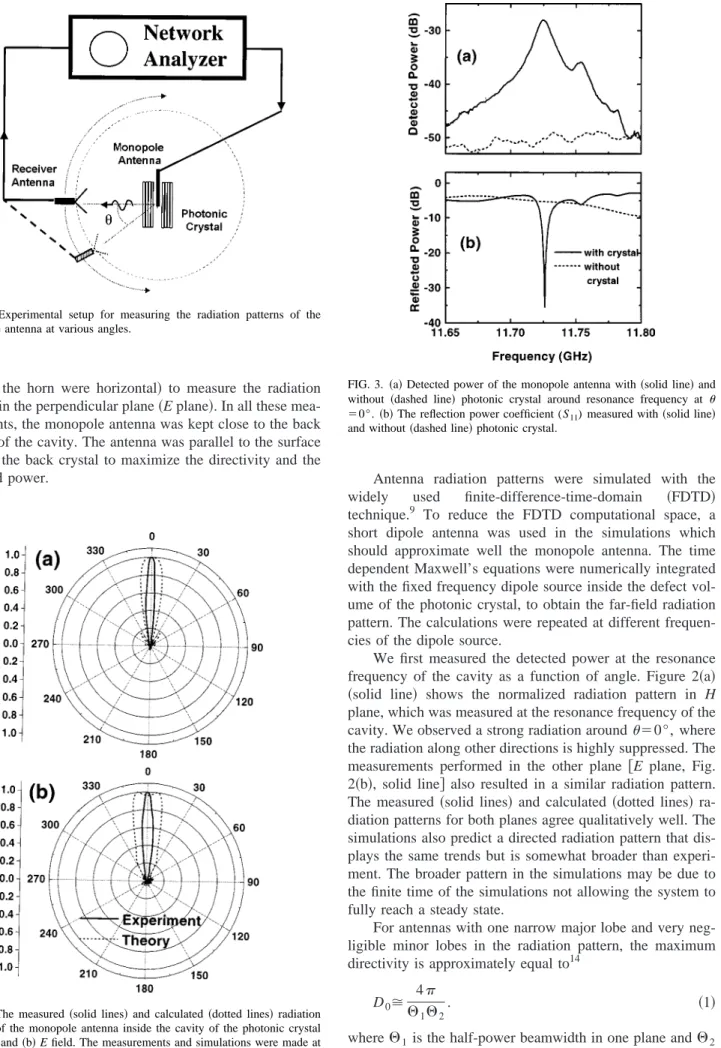
FIG. 3. 共a兲 Detected power of the monopole antenna with 共solid line兲 and without 共dashed line兲 photonic crystal around resonance frequency at
⫽0°. 共b兲 The reflection power coefficient (S11) measured with共solid line兲
and without共dashed line兲 photonic crystal.
604 J. Appl. Phys., Vol. 87, No. 1, 1 January 2000 Temelkuranet al.
sured half-power beamwidth along the H plane 关Fig. 2共a兲兴 was 11°, and was 12° along the E plane 关Fig. 2共b兲兴. These values lead to a directivity value around 310.
Figure 3共a兲 共solid line兲 shows the detected power as a function of frequency at⫽0°. The dotted line displays the detected power at the same angle in the absence of the pho-tonic crystal. At resonance frequency, we observed a power enhancement factor of 180共22.6 dB兲 at a defect frequency of 11.725 GHz. The radiated EM field from the monopole an-tenna has also frequency selectivity introduced by the cavity. The Q factor共quality factor兲, defined as the center frequency divided by the full width at half maximum, was measured to be 895.
In order to understand the effect of the resonator to the efficiency of the monopole antenna, we also measured the S parameters of our antenna structure. Figure 3共b兲 shows the reflection power coefficient (S11) which is 30%共⫺5 dB兲 for
the monopole antenna standing alone in air. This implies that the antenna radiates only 70% of the incoming power. When the antenna was inserted inside the cavity, we observed a very sharp drop 共⫺35 dB兲 at resonance frequency in the reflection spectra 关Fig. 3共b兲, solid line兴. This drop indicates that most of the power共99.97%兲 is radiated out in the pres-ence of the cavity. The maximum radiation gain for our an-tenna is related to the maximum directivity by G0⫽(1⫺R)
⫻(1⫺A)D0, where R is the reflected power and A is the
absorptivity of the antenna. In our case, the reflectivity at the resonance frequency is very small 共0.0003兲. Assuming that the absorption in the antenna has a negligible value, the maximum gain has a value ⬃300.
Such a planar cavity built around a 3D photonic crystal should not be confused with the Fabry–Perot type of resona-tors that are constructed by using distributed Bragg reflecresona-tors
关which are known as one-dimensional 共1D兲 photonic
crys-tals兴. In the former structure, the EM field is always coupled to the evanescent defect mode within the band gap irrespec-tive of the incidence angle. However, the resonant frequency shifts as the angle of incidence of the EM wave changes in the latter case.15,16It is obvious that for planar waves, 3D and 1D resonant structures will result in similar enhancements and directivities. In our case, the monopole antenna radiates in all directions, and all the power radiated is coupled to the evanescent mode of the defect, regardless of the direction. This is the reason we have an antenna with a very high efficiency 关see Fig. 3共b兲兴. However, for a 1D structure, the radiated EM field, except a certain direction, will not be coupled to the corresponding resonant mode of the cavity.
Although our structure is suitable for narrow bandwidth applications, one can tune the defect frequency to any de-sired value by adjusting the width of the cavity. We observed that the resonance frequency could be tuned within a fre-quency range extending from 10.6 to 12.8 GHz, which cor-responds to the full band gap of our photonic crystal. The directivity drops to values around 100 at the band edges, and reaches a peak value of 310 at 11.7 GHz.
In conclusion, we have investigated the radiation char-acteristics of a photonic crystal-based antenna. The maxi-mum directivity we have measured, which is around 310, is very high when compared to the previously reported direc-tivities of photonic crystal based antennas. There’s a good agreement between the measurements and the FDTD calcu-lations.
This work is supported by NATO Grant No. SfP971970, National Science Foundation Grant No. INT-9812322, and NATO-Collaborative Research Grant No. 950079. Ames Laboratory is operated for the U.S. Department of Energy by Iowa State University under Contract No. W-7405-Eng-82.
1J. D. Joannopoulos, R. D. Meade, and J. N. Winn, Photonic Crystals 共Princeton University Press, Princeton, NJ, 1995兲.
2
For a recent review, see articles in Photonic Band Gap Materials, edited by C. M. Soukoulis共Kluwer, Dordrecht, 1996兲.
3S. Fan, P. R. Villeneuve, J. D. Joannopoulos, and H. A. Haus, Phys. Rev.
Lett. 80, 960共1998兲.
4
J. G. Fleming and S. Y. Lin, Opt. Lett. 24, 49共1999兲.
5
E. Ozbay, J. Opt. Soc. Am. B 13, 1945共1996兲.
6M. C. Wanke, O. Lehmann, K. Muller, Q. Wen, and M. Stuke, Science 275, 1284共1997兲.
7K. A. McIntosh, L. J. Mahoney, K. M. Molvar, O. B. McMahon, S.
Verghese, M. Rothschild, and E. R. Brown, Appl. Phys. Lett. 70, 2937 共1997兲.
8E. R. Brown, C. D. Parker, and E. Yablonovitch, J. Opt. Soc. Am. B 10,
404共1993兲.
9
M. M. Sigalas, R. Biswas, Q. Li, D. Crouch, W. Leung, R. Jacobs-Woodbury, B. Lough, S. Nielsen, S. McCalmont, G. Tuttle, and K. M. Ho, Microwave Opt. Technol. Lett. 15, 153共1997兲.
10E. R. Brown and O. B. McMahon, Appl. Phys. Lett. 68, 1300共1996兲. 11G. Poilasne, P. Pouliguen, K. Mahdjoubi, J. Lenormand, C. Terret, and Ph.
Gelin, Microwave Opt. Technol. Lett. 18, 32共1998兲.
12B. Temelkuran, E. Ozbay, J. P. Kavanaugh, G. Tuttle, and K. M. Ho,
Appl. Phys. Lett. 72, 2376共1998兲.
13B. Temelkuran and E. Ozbay, Appl. Phys. Lett. 74, 486共1999兲. 14
C. A. Balanis, Antenna Theory: Analysis and Design共Wiley, New York, 1997兲, p. 45.
15A. Yariv and P. Yeh, Optical Waves in Crystals共Wiley, New York, 1984兲. 16E. F. Schubert, N. E. J. Hunt, A. M. Vredenberg, T. D. Harris, J. M. Poate,
D. C. Jacobson, Y. H. Wong, and G. J. Zydzik, Appl. Phys. Lett. 63, 2603 共1993兲.
605
J. Appl. Phys., Vol. 87, No. 1, 1 January 2000 Temelkuranet al.