Experimental and numerical analyses of the resonances
of split ring resonators
Koray Aydin* and Ekmel Özbay
Nanotechnology Research Center-NANOTAM, Department of Physics,
Department of Electrical and Electronics Engineering, Bilkent, 06800 Ankara, Turkey
Received 19 September 2006, accepted 19 January 2007 Published online 22 March 2007
PACS 41.20.Jb, 42.25.Bs, 42.70.Qs
The authors investigate the resonances of split-ring resonator (SRR) structures experimentally and theo-retically. The transmission measurements were performed on a single SRR unit cell and periodic arrays of SRRs. The magnetic response of the SRR structure was demonstrated by comparing the SRRs’ transmis-sion spectra of with that of closed ring resonators (CRR). The surface currents along the SRR surfaces at the magnetic and electrical resonances were simulated and a circular surface current was observed at the magnetic resonance frequency. The transmission characteristics of SRR arrays with two different orienta-tions were also presented by varying the incident angles of the plane wave.
© 2007 WILEY-VCH Verlag GmbH & Co. KGaA, Weinheim
1 Introduction
Artificially constructed materials may exhibit different physical characteristics that are not attainable by ordinary materials. In recent years split ring resonators (SRR) received a growing amount of interest since such structures may lead to negative values of permeability. Pendry et al. proposed that SRRs built from nonmagnetic thin sheets of metal possess a wide range of effective magnetic permeability values including negative ones [1]. Later experimental and theoretical studies have shown that SRR media, when combined properly with thin wire media, may exhibit left-handed properties [2 – 5]. Since SRR structures are quite undiscovered and are the essential components of LHMs, a considerable amount of effort has been made in order to understand the underlying physics of SRRs [6 – 16]. The studies on SRRs and metamaterials are mainly performed at the gigahertz (GHz) frequency regime because of their ease of fabrication. However, recently there has been a tendency to increase the magnetic resonance frequencies of SRRs up to terahertz (THz) frequencies [17, 18].
In this present work, we studied the behavior of resonances (both magnetic and electrical) experimen-tally and theoretically. We first present the measurements and simulations on the single unit cells of SRRs and closed ring resonators (CRR). We also performed simulations to observe the surface currents on magnetic and electrical resonances. Later, we show the results on the arrays of SRR and CRR struc-tures. Finally, we vary the angle of incidences in order to understand the band gap formation at the trans-mission spectra of SRR structures.
2 Magnetic resonance from a split-ring resonator unit cell
Split-ring resonator structures are built from nonmagnetic concentric copper rings with splits oriented at opposite sides. Figure 1(a) shows a schematic drawing of a single SRR. The width of the splits and the
Fig. 1 (online colour at: www.pss-b.com) Schematic drawing of a single (a) split-ring resonator, (b) closed ring resonator, and (c) SRR rotated with 90°.
gap between the inner and outer rings are 0.2 mm, the metal width is 0.9 mm, and the outer radius is 3.6 mm. SRR is deposited on a dielectric board with a thickness of 1.6 mm and ε = 3.85.
The resonant behavior of SRR is due to capacitive elements (gaps and splits), which in turn results in rather high positive and negative values of permeability close to the magnetic resonance frequency (ωm). If a single SRR unit cell is excited with an EM wave with the appropriate polarization, the SRRs respond to the magnetic component of the incident field due to the magnetic resonance. The splits in the SRR structure play a key role in obtaining magnetic resonance. Removing the splits prevents the current from flowing between the inner and outer rings, and therefore, the magnetic resonance is destroyed. The clo-sed ring resonator (CRR) is shown in Fig. 1(b).
We measured the frequency response of SRR and the CRR unit cells. Two monopole antennas were used to transmit and detect the EM waves through the single SRR unit cell. Monopole antennas were then connected to the HP-8510C network analyzer in order to measure the transmission coefficients. The incident EM wave propagates along the x direction, with an electric field (E) and magnetic field (H) along the y and z directions, respectively.
Figure 2(a) shows the measured frequency response of single SRR (blue) and CRR (red) structures. Throughout the frequency spectrum for the SRR case, three transmission dips were observed at 3.82, 8.12, and 10.90 GHz. However, for the CRR case a single dip was measured at 10.92 GHz. We also performed simulations to check the experimental results. Simulations were performed by using commer-cial software, CST Microwave Studio, which is a 3D full-wave solver, employs the finite integration technique (FIT). The simulation results that are shown in Fig. 2(b) are in good agreement with the ex-periments.
For the CRR, no magnetic resonance was observed. However, for the SRR we observed two magnetic resonances at ωm1 = 3.82 GHz and ωm2 = 8.12 GHz. The SRR structure not only exhibits magnetic resonance induced by the splits at the rings, but electric resonance is also present via the dipole-like charge distribution along the incident electric field. Such an electric resonance behavior is observed at
Fig. 2 (online colour at: www.pss-b.com) Frequency response of single SRR (blue) and CRR (red) unit cells that were obtained from (a) experiments, and (b) simulations.
ωe ≈ 10.90 GHz for the SRR and CRR. Closing the split affected the electrical resonance but destroyed
the magnetic resonance.
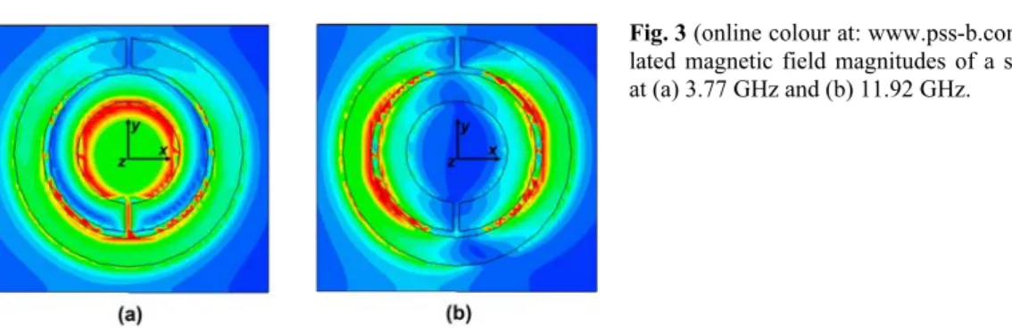
We also performed simulations in order to monitor the magnitude of the magnetic field at the SRR structure by using Microwave Studio. The simulations were performed at 3.77 GHz and 11.92 GHz, which correspond to the transmission dip in the simulated transmission spectrum of SRR (former is the magnetic, latter is the electrical resonance). The magnitude of the magnetic fields are shown in Fig. 3. As clearly seen in Fig. 3(a), a circular current is present at the SRR. Such a circular current excites the mag-netic resonance, and therefore, a transmission dip was observed at 3.77 GHz in simulations. However, the behavior of the magnetic field changes at 11.92 GHz (see Fig. 3(b)). The direction of the current flow is not circular, but rather an up-down direction. Since the current is not circular the magnetic resonance cannot be excited. The transmission dip at this frequency can only be due to the electrical resonance of the ring resonator structure.
3 Periodic arrays of split-ring resonators
In the previous section we performed measurements and simulations on a single unit cell of SRR and CRR. We further simulated and measured the transmission through periodic SRR and CRR media. A band gap in the transmission spectrum of a periodic SRR medium might be due to negative ε or negative µ, or solely due to the periodicity. A frequency gap that is present in the transmission spectrum of SRR medium, but that is not in the CRR medium, will correspond to µ < 0. In the measurements, the number of unit cells along the x, y, and z directions are Nx = 10, Ny = 20, and Nz = 25. The incident EM wave propagates along the x direction, while E is along the y direction, and H is along the z direction (refer to Fig. 1(a) for the directions).
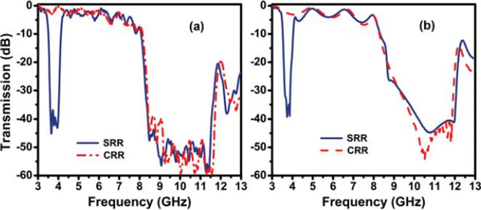
Figure 4(a) shows the measured transmission spectra of periodic SRRs (blue solid line) and CRRs (red dashed line) between 3 – 13 GHz. The first band gap in the transmission spectrum of the SRR
Fig. 4 (online colour at: www.pss-b.com) Transmission spectra of periodic SRR (blue) and CRR (red) arrays obtained from (a) experiments and (b) simulations.
lated magnetic field magnitudes of a single SRR at (a) 3.77 GHz and (b) 11.92 GHz.
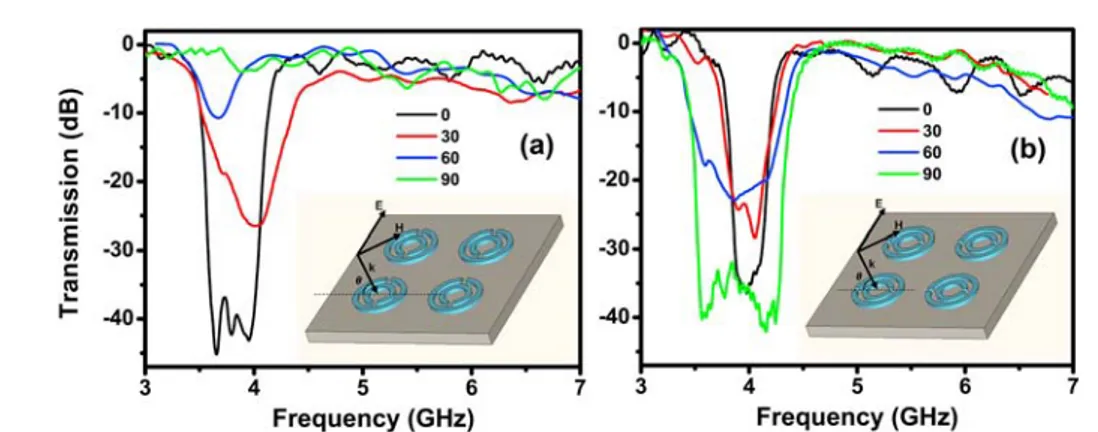
Fig. 5 (online colour at: www.pss-b.com) Transmission spectra of periodic SRR arrays with varying angles of incidences obtained for (a) normal SRR and (b) 90° rotated SRR. The insets show the SRRs’ orientations and the directions of the field components.
medium between 3.55 – 4.07 GHz is not present in the CRR medium. However, the second band gap (8.20 – 11.90 GHz) is present for the SRR and CRR arrays. Simulation results provided in Fig. 4(b) agrees well the experimental data. Therefore, the first band gap is due to the magnetic resonance induced by the splits, and therefore, permeability becomes negative throughout the band gap. These measure-ments and simulations clearly show that the stop bands of an SRR medium cannot be assumed as a result of “negative µ” behavior. Some of the observed gaps (such as a second band gap in this measurement) in the transmission spectra could also originate from the electrical response of the SRRs or from Bragg gaps due to periodicity. In a recent study, we extracted the effective parameters of an SRR array by em-ploying a retrieval procedure [19]. The effective permeability was calculated to be negative within the first stop band of SRR, which is in agreement with the observed behavior in this present study.
Negative magnetic permeability is only achievable via parallel polarization, where the wave vector is parallel to the SRR plane and the H-field is along the z-axis. A magnetic field, when perpendicular to the SRR plane, induces current loops at the resonance. However, it is not possible to obtain a magnetic re-sponse from the SRR structure if the magnetic field is parallel to the SRR plane. On the other hand, it has been recently argued that for the specific orientation of the SRR and polarization of an incident EM wave, it is possible to obtain resonance due to electric field excitation [6]. This effect is called “electric excitation of the magnetic resonance (EEMR)” and is due to the bianisotropy of the conventional SRR design. This effect is a useful tool for obtaining magnetic responses of bianisotropic SRRs at higher frequencies, such as THz frequencies [18]. For parallel polarization one needs to stack many SRR sam-ples, and therefore, much more time is required to fabricate such structures. However, rather few samples are sufficient to “indirectly” observe the cross-polarization effect by making use of the perpendicular polarization.
In a recent work, Gundogdu et al. studied the EEMR effect by varying the angle of incidences of the incident plane wave [20]. They placed a 5 layer SRR metamaterial and measured the transmission and reflection coefficients. However, the range of the incident angles was not large as a result of the low number of layers. We employed two different SRR orientations at angles of incidences varying between 0 – 90°. One is the normal SRR as shown in Fig. 1(a) and the other is the 90° rotated SRR as in Fig. 1(c). The insets of Fig. 5(a) and (b) show the schematic drawing of the experimental method that we em-ployed. The E-field is always along the y direction for all the angles of incidences and the k–H plane is rotated around the y axis from 0 to 90 degrees. The case for 0° corresponds to the parallel propagation and 90° corresponds to the perpendicular propagation. It is noteworthy that magnetic resonance is only possible with parallel propagation. The data and inset of Fig. 5(a) and (b) belong to the normal SRR and rotated SRR orientations, respectively.
Figure 5(a) shows the transmission spectrum of SRR with varying incident angles of 0, 30, 60, and 90°. For θ = 0°, there is a well-defined band gap as was discussed in the previous part of this section. The
transmission within the band gap increases when the incident angle is increased to 30°. Increasing θ to 60° results in a further increase in the transmission. The magnetic resonance becomes weaker and weaker with the increase in the incident angles, in which the band gap disappears for the perpendicular propagation i.e., for θ = 90°. Interestingly, the behavior changes for the rotated SRR case, since the E-field is no longer symmetric regarding the SRR. The electrical excitation of magnetic resonance is possible for this orientation. The transmission results shown in Fig. 5(b) support this statement. For all the angles of incidences, there appears a band gap at the measured transmission spectra of SRR. At θ = 0°, magnetic resonance is present and the band gap is narrower. However, at 90°, electric resonance asserts itself and a wider band gap is observed. The evolution of the band gap for the incident angles from 0 to 90° is clearly seen in Fig. 5(b).
4 Conclusion
To conclude, we investigated the transmission properties of single SRR and CRR unit cells excited with a point monopole source, and periodic SRR and CRR arrays shined with plane waves. The simulations and measurements confirmed that at certain frequencies SRR structures have magnetic resonances. By making a comparison between SRR and CRR arrays, the magnetic resonances can be found easily. We also performed simulations in order to observe how the surface currents flow at magnetic and electrical resonances. Circular currents flow along the SRR surfaces at the magnetic resonance; however, the be-havior of the currents at the electric resonance is quite different. The EEMR effect is shown by varying the incident angles of a plane wave.
Acknowledgements This work is supported by the European Union under the projects EU-NoE-METAMOR-PHOSE, EU-NoE-PHOREMOST, and TUBITAK under Projects Nos. 104E090, 105E066, 105A005, and 106A017. One of the authors (E.O.) also acknowledges partial support from the Turkish Academy of Sciences.
References
[1] J. B. Pendry, A. J. Holden, D. J. Robbins, and W. J. Stewart, IEEE Trans. Microw. Theory Tech. 47, 2075 (1999).
[2] D. R. Smith, W. J. Padilla, D. C. Vier, S. C. Nemat-Nasser, and S. Schultz, Phys. Rev. Lett. 84, 4184 (2000). [3] R. A. Shelby, D. R. Smith, and S. Schultz, Science 292, 77 (2001).
[4] K. Aydin, K. Guven, M. Kafesaki, L. Zhang, C. M. Soukoulis, and E. Ozbay, Opt. Lett. 29, 2623 (2004). [5] K. Aydin, K. Guven, C. M. Soukoulis, and E. Ozbay, Appl. Phys. Lett. 86, 124102 (2005).
[6] N. Katsarakis, T. Koschny, M. Kafesaki, E. N. Economou, and C. M. Soukoulis, Appl. Phys. Lett. 84, 2943 (2004).
[7] K. Aydin, K. Guven, N. Katsarakis, C. M. Soukoulis, and E. Ozbay, Opt. Express 12, 5896 – 5901 (2004). [8] P. Gay-Balmaz, and O. J. F. Martin, J. Appl. Phys. 92, 2929 – 2936 (2002).
[9] K. Aydin, I. Bulu, K. Guven, M. Kafesaki, C. M. Soukoulis, and E. Ozbay, New J. Phys. 7, 168 (2005). [10] J. García-García, F. Martín, J. D. Baena, R. Marques, and L. Jelinek, J. Appl. Phys. 98, 033103 (2005). [11] R. Marques, F. Mesa, J. Martel, and F. Medina, IEEE Trans. Antennas Propag. 51, 2572 (2003). [12] D. R. Smith, J. Gollub, J. J. Mock, W. J. Padilla, and D. Schurig, J. Appl. Phys. 100, 024507 (2006). [13] M. Shamonin, E. Shamonina, V. Kalinin, and L. Solymar, J. Appl. Phys. 95, 3778 (2004).
[14] V. Varadan, Z. Sheng, S. Penumarthy, and S. Puligalla, Microw. Opt. Technol. Lett. 48, 1549 (2006). [15] K. Aydin and E. Ozbay, Opto-Electron. Rev. 14, 193 (2006).
[16] K. Aydin and E. Ozbay, J. Appl. Phys. 101, 024911 (2007).
[17] T. J. Yen, W. J. Padilla, N. Fang, D. C. Vier, D. R. Smith, J. B. Pendry, D. N. Basov, and X. Zhang, Science 303, 1494 (2004).
[18] S. Linden, C. Enkrich, M. Wegener, J. Zhou, T. Koschny, C. M. Soukoulis, Science 306, 1351 (2004). [19] K. Aydin, I. Bulu, and E. Ozbay, Microw. Opt. Technol. Lett. 48, 2548 (2006).
[20] T. F. Gundogdu, I. Tsiapa, A. Kostopoulos, G. Konstantinidis, N. Katsarakis, R. S. Penciu, M. Kafesaki, E. N. Economou, T. Koschny, and C. M. Soukoulis, Appl. Phys. Lett. 89, 084103 (2006).