Journal of Physics: Conference Series
Front-end Assembly Optimization for High-T
c
rf-SQUID based Magnetic Field Imaging Systems
To cite this article: R Akram et al 2006 J. Phys.: Conf. Ser. 43 1239View the article online for updates and enhancements.
Related content
Signal enhancement techniques for rf SQUID based magnetic imaging systems
Rizwan Akram, Mehdi Fardmanesh, Juergen Schubert et al.
-High-sensitivity microwave RF SQUID operating at 77 K
Y Zhang, M Muck, A I Braginski et al.
-Considerations on the read out of low frequency NMR for 3He
O W B Benningshof, D H Nguyen and R Jochemsen
Front-end Assembly Optimization for High-T
crf-SQUID
based Magnetic Field Imaging Systems
R. Akram1,2 , M. Fardmanesh2 , J. Schubert3 , W. Zander3 , M. Banzet3 , D. Lomparski3, M. Schmidt3,4, and H.-J. Krause3.
1) Department of Physics, Izmir Institute of Technology, 35430 Urla, Izmir, Turkey. 2) Electrical and Electronics Engineering Department, Bilkent University, 06800 Bilkent, Ankara, Turkey. 3) SG1-IT, Forschungszentrum Jülich GmbH, 52425 Jülich, Germany.
4) Biotechnological Biomedical Center, University of Leipzig, Deutscher Platz 5, 04103 Leipzig, Germany.
Abstract. We have investigated the rf-SQUID and its coupling to the tank circuit
configurations to achieve an optimal front-end assembly for sensitive and high spatial resolution magnetic imaging systems. The investigation on the YBCO rf-SQUID coupling to the conventional LC tank circuits revealed that the coupling from the back of the SQUID substrate enhances the SQUID signal while facilitating the front-end assembly configuration. The optimal thickness of the substrate material between the SQUID and the tank circuit is
0.4mm for LaAlO3 resulting in an increase of SQUID flux-voltage transfer function signal, Vspp,
of 1.5 times, and 0.5 mm for SrTiO3 with an increase of Vspp of 1.62 times compared to that of
direct face to face couplings. For the rf-coupling with co-planar resonator, CPR, it has been found that the best configuration, in which a resonator is sandwiched between the SQUID
substrate and resonator substrate, provides a Vspp about 3.4 times higher than the worse case
where the resonator and the SQUID are coupled back to back. It has also been observed that the noise level does not depend considerably on whether a conventional LC tank circuit or a CPR is used. Though the use of resonator leads to a limitation of the achievable spatial resolution due to its flux-focusing characteristics. This resulted in favouring the use of the
conventional tank circuits when considering the desired high spatial resolution.Effect of the
YBCO flip-chip magnetic shielding of the SQUIDs in the back coupling with the LC-tank circuit configuration has also been investigated, in order to reduce the SQUID effective area to increase the spatial resolution and also to study the effect of the coupling of various types of the transformers to the SQUIDs. It is revealed that there is no considerable change in the flux-voltage transfer function signal level with respect to the effective shield area, while the lowest working temperature of the SQUIDs was slightly shifted higher by a couple of degrees depending on the shield area.
1. Introduction
For the sensitive applications of rf-SQUID based magnetic imaging systems, where high magnetic field sensitivity with high spatial resolution is required, two important issues to be considered are the front-end assembly of the SQUID microscope and the SQUID flux to voltage transfer function signal level, Vspp [1], [2]. With respect to the system design, use of high-Tc SQUIDs is superior compared to
Institute of Physics Publishing Journal of Physics: Conference Series 43 (2006) 1239–1242
doi:10.1088/1742-6596/43/1/302 7th European Conference on Applied Superconductivity
1239 © 2006 IOP Publishing Ltd
the low-Tc devices, mainly due to the Lift-off distance (LOD), the distance between the SQUID and the sample, which plays a vital role for front-end assembly. LOD is inevitably widened for Helium based systems, whereas it can be decreased down to few tens of microns in Nitrogen based systems by using a thin window. Designing such a system offers serious challenges especially when it is required to work on samples at room temperature, which further more requires precise separation adjustment system. Bottlenecks allied to this kind of applications of the SQUID based systems are highlighted and investigated in this work. In this study we have probed some of these limiting factors, which not only provide insight to improve the sensitivity and field resolution, but also helps in development of new configurations for the front-end assembly of high resolution magnetic field imaging systems [3], [4].
2. rf coupling configurations
Both field sensitivity and spatial resolution of SQUID microscopes are highly dependent on the distance between the sensor and the sample. Hence, we have investigated various approaches to couple the rf-SQUID sensor and the samples to find the optimal configuration. The high field
sensitivity of
high Tc rf-SQUIDs is also associated with its large area layout where this inherited limitation hinders the high spatial resolution. This is while the washer area of the SQUIDs can be optimized for minimum area needed for efficient coupling to the rf-coupling circuit [4].
As a replacement for the conventional LC tank circuit, which not only provides less Vspp but also takes more space and thus hindering the front-end assembly, thin film superconducting coplanar resonators was used and investigated in flip chip configuration [5]. In the case of the coplanar resonator, we used either 8mm rectangular (SR8) or a 13.4mm circular (SR13) layout designs with integrated flux concentrators [5]. The difference in the performance of the SQUID using the above couplings was investigated. As shown in Figure 2a, the Vspp is an order of magnitude higher in the case of co-planar resonator compared to LC tank circuit. The noise level of the SQUIDs has not been found to be dependent much on the type of the rf-coupling technique [6], favoring the use of the tank circuit when considering the desired high spatial resolution. It is to be noted that the use of coplanar resonators with integrated flux concentrators introduces serious limitations in the spatial resolution. The coupling possibilities with coplanar resonator that were investigated are shown in Figure 1a.
Results obtained from systematic study of the coupling techniques for resonator, SQUID, and the pick up coil of the electronics are listed in Table 1. In type ‘B’ configuration of Figure 1a where there is a substrate between the SQUID and the resonator and a substrate between the resonator and the pick up coil, it has been observed that both higher SQUID signal level and noise reduction can be achieved. The improvement in the signal level compared to the worse case, D, is about 3.4 times. Above results provide insight to two important facts: a) Distance between resonator and the coupling coil provides
0,0 0,1 0,2 0,3 0,4 0,5 0,6 0,7 0,8 0,9 1,0 50 100 150 200 250 300 350 400 450 500 550 50 100 150 200 250 300 350 400 450 500 550 V spp for LaAlO3 V spp for SrTiO3 Per iod of SQ UID s igna l ( m V/ Φ 0) S Q UID S ign al [V spp ]( m V ) Substrate Thickness (mm) Phase for LaAlO3 Phase for SrTiO3 Optimum Thickness
Figure 1: a) Basic possible configurations for resonator to SQUID coupling. b) Effect of substrate (LaAlO3 and SrTiO3) thickness
between SQUID and LC tank circuit. (a) (b)
better signal coupling with electronics; b) Dielectric material between the SQUID and the resonator improves the SQUID signal level, Vspp.
Type Description Vspp Level Quality
A S-R-sub-C 900 mV Lockable
B S-sub-R-sub-C 1.18 V Lockable and less noisy
C S-sub-R-C 400 mV Lockable and noisy
D S-sub-sub-R-C 350 mV Barely lockable and noisy
Table 1: Possible SQUID and the coplanar resonator coupling configurations with their relative signal and signal locking states. [S: SQUID, R: Resonator, sub: substrate, C: pick up coil electronics]
3. Substrate thickness effect
As theoretically expected and seen in Table 1, the SQUID signal improves by introducing dielectric material in the gap between the coupling circuit and the SQUID for both cases of coplanar resonators and the LC tank circuit. This effect has been investigated by introducing the substrate material with various thicknesses, between the SQUID and the LC tank circuit for two types of the used substrate materials, namely LaAlO3 and SrTiO3. The effect of the substrate thickness on the SQUID signal, Vspp, for both LaAlO3 and SrTiO3 materials is shown in Figure 1b. As shown in the figure, the optimum substrate thickness was found to be about 0.4mm for LaAlO3 and 0.5 mm for SrTiO3 substrate materials. To reach the optimal substrate thicknesses one should thin the substrates either prior to the SQUID fabrication or after, where both were proven to be possible [7], [8]. Devices with various substrate thicknesses were made and characterized and presented else where [8].
4. Shielding effect
It has been observed that noise coupling from the resonator circuit is very much influential in most of the applications. This is especially in the case when pick up transformers are being used to increase the spatial resolution [3]. In such cases, field sensing is not only due to the SQUID but also due to the resonator and the transformer legs which serve as sensing devices, and add up to the noise. To overcome this hurdle, the solution of shielding of the unwanted areas has been investigated in details. In order to determine the shielding factor, SQUIDs have been covered with 1cm2
YBCO thick film acting as a magnetic shield. Theoretical expectation for shielding factor of a 1cm2
shield applied to SQUID through a substrate of about 1mm thickness is about 10 [9], whereas experimentally obtained data shows a best results of 8.67 for small washer area SQUID. The measured shielding factor shows inverse dependence on the SQUID’s washer area and it shows linear behavior with respect to the applied field. This leads to the fact that proper shielding of the SQUID can be achieved by having smaller washer area for the case when a transformer is used to pickup the signal [10]. The possibility
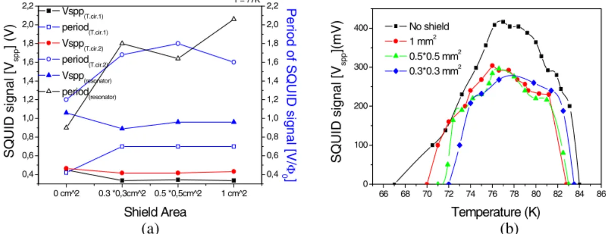
0 cm^2 0.3 *0,3cm^2 0.5 *0,5cm^2 1 cm^2 0,4 0,6 0,8 1,0 1,2 1,4 1,6 1,8 2,0 2,2 0,4 0,6 0,8 1,0 1,2 1,4 1,6 1,8 2,0 2,2 T = 77K Pe ri od of SQU ID si gn al [V/ Φ 0] Vspp (T.cir.1) period (T.cir.1) Vspp (T.cir.2) period (T.cir.2) Vspp (resonator) period (resonator) S Q UI D s ig n a l [ Vsp p ] (V) Shield Area 66 68 70 72 74 76 78 80 82 84 86 0 100 200 300 400 No shield 1 mm2 0.5*0.5 mm2 0.3*0.3 mm2 SQUI D si gnal [ Vsp p ](m V ) Temperature (K)
Figure 2: Effect of the applied shield area, (a) Tank circuit 1 and 2 are conventional LC tank circuits but the loop diameter of inductor for tank circuit 1 is small and for 2 is larger. Resonator circuit is conventional superconducting circular washer type. (b): Effect of
temperature on the Vspp of the shielded SQUID.
(a) (b)
of suppressing the SQUID signal by applying a shield in different coupling techniques has been investigated by covering the SQUID washer area with 200nm YBCO film. The measured unlocked signal of the test SQUID is shown in Figure 2a.
From the above graph of figure 2a for tank circuit 1, it is clear that an increase of shield area from 0 to 1cm2 causes about 16.2% decrease in Vspp, while the phase of the SQUID signal is increased by 82%. Therefore, for the applications, where Vspp is being observed as a main entity, shielding does not considerably affect the over all measurement. It has also been observed that application of rf-coupling type not only affects the SQUID signal level, but also causes suppression in the signal level when applying a shield. It is clear from Figure 2a that resonator provides 2.28 times better signal level compared to that obtained by the LC tank circuit. But on the other hand, shielding affects adversely the resonator coupling by decreasing the signal level by 10-20%, whereas in optimized LC tank circuit, it is just about 7% depending on the applied shield area.
In order to investigate the reason for reduction in the signal of the SQUID by the use of the shield, temperature sensitivity vs. shielding effect on Vspp of the devices has been measured and shown in Figure 2b. Theoretically, the inductance of the SQUID changes by applying a shield, and this inductance change of loop causes a change in the bias point. In such situation, increase of the temperature revealed the SQUID signal back, which refers to the need of a SQUID with higher Jc than that calculated for an unshielded SQUID. This way inductance and current product will remain the same under shielding for optimum temperature, which in our case is 77K. From Figure 2b, it is clear that such an intersection point can be found by increasing the temperature, where signal with shield is equal to that without the shielding. This leads us to optimize the SQUID design with the desired Jc for optimum operation under shielding conditions.
5. Conclusion
The bottlenecks related to the applications of the rf-SQUID for high spatial and high field-sensitivity resolutions have been systematically investigated. In this study, the liquid Nitrogen based systems were used since they provide better solution for possibility of the use of just a thin window concept to reduce the lift-off distance. Both the coplanar resonator and the conventional LC tank circuit based configurations were investigated. Although the used coplanar resonators provided better signal level compared to conventional LC tank circuits for bare SQUIDs without shield, but optimized conventional LC tank obtained by decreasing the diameter of the pick up loop to provide the high Vspp were advantageous due to lower suppression of the SQUID signal under shielding and lower unwanted pickup caused by the large flux focusing area of the coplanar resonators. The LC tank circuit also provides less percentage suppression under shielding compared to the coplanar resonators. Shielding effect on coupling techniques and with respect to temperature on the Vspp has also been investigated. This investigation can be concluded as; a) Film used for shielding should be as thick as possible (~ 400nm – 500nm), so that better shielding factor can be achieved, b) SQUIDs with relatively higher Jc are required as under shielding the reduction in the inductance by the shield is compensated.
References
[1] K. Enpuku et al., IEEE Trans. Appl. Supercond., vol. 11, pp. 661-664, 2001. [2] Y. R. Chemla et al., Proc Nat Acad Sci USA 97 pp. 14268-14272, 2000. [3] R. Akram, PhD thesis, Bilkent university, Ankara, Turkey, 2005. [4] M. Schmidt et al., ISE, Holand, 2005.
[5] Y. Zhang et al., Appl. Superconductivity, vol. 6, pp. 358-390, 1998.
[6] M. Fardmanesh et al., Appl. Superconductivity, vol. 11, pp. 3363-1366, 2001. [7] R. Akram, Project Report, Forschungszentrum Jülich, Germany, 2003. [8] M. Schmidt, Diplomarbeit, Forschungszentrum Jülich, Germany, 2003.
[9] T. Van Duzer and W. T. Charles, “Superconductive Devices and Circuits”, 2nd Ed. PTR PH. [10] E. J. Tarte et al., IEEE Trans. Appl. Supercond, vol. 7, pp. 3662-3665, 1997.