RESEARCH ARTICLE
IMPROVEMENT AN COST ANALYSIS OF BLASTING OPERATIONS AT WESTERN LIGNITE OPEN CAST MINE
Şahin YUVKA1, Emre DURAN2*, Önder UYSAL3
1KütahyaDumlupinar University, Department of Mining Engineering, Kutahya, [email protected], ORCID: 0000-0002-3219-2321
2Turkish Coal Enterprises, Garp Lignite Corporation,Kutahya, [email protected], ORCID: 0000-0001-7567-2790
3Kütahya Dumlupinar University, Department of Mining Engineering, Kutahya, [email protected] , ORCID: 0000-0002-3640-3341
Geliş Tarihi:11.06.2020 Kabul Tarihi: 29.06.2020
ABSTRACT
Drilling and blasting operations have a great importance in mining operations. By means of drilling and blasting operations, ease of excavability is provided and production can be made in desired particle sizes especially for ore. In this study, state-operated blasting operations in Western Lignite Corporation mining sites and problems encountered in these blasting operations are investigated. It was aimed to solve the problem of encountering blocks after blasting by using nitroglycerine based cast boosters instead of emulsion based cast boosters. The blasting shots and excavation loading works in the blasting area were recorded. The muckpile images obtained after blasting operations were examined with WipFrag software and particle size distributions were checked. According to the data obtained, cost analyzes related to blasting and transportation were performed. It was found that after the change, the problems decreased and the company economically gained 25% annually in terms of blasting costs.
Keywords: Blasting Costs, Particle Size Analysis, Problems With Blasting 1. INTRODUCTION
Minerals and elements extracted from different depths of the earth's crust are called as ore. Mining works involve the exploration, project design, operation of the ore deposits and enrichment of the mined ore. [1]
Mining activities have a large share in the country's economies. Mining activities are basically carried out by two methods. These methods are Open Pit Mining and Underground Mining. Both production methods include development, drilling and blasting, excavation, loading and haulage. Depending on the properties of the mine and the method of production, the equipment to be used and the way it works varies.
Considering the expenditures made during mining activities, drilling and blasting costs are of great importance as they will affect consecutive operations such as loading, transportation and breaking. [2] In order to reduce these costs, the most suitable drilling and blasting design is required.
Drilling and blasting design varies according to the geological structure, the properties of the mine, the characteristics of the equipment used, the desired particle size and environmental effects. In addition to all these factors, the hole parameters (such as hole diameter and angle, zone thickness, hole length, hole pattern, toe share and stemming length, distance between holes, shape of bench face, dispersion and quantity of the explosive in the hole, cast booster, detonation type and order, delay type and duration) are also of great importance during the blasting design. Therefore, drilling and blasting processes should be evaluated as a whole. [3]
Many problems can be encountered during drilling and blasting operations. Mistakes made during drilling, such as the hole lenght not the same, hole diameters are not equal and angle of holes are wrong, may affect the yield to be obtained from the blasting process. [4] Problems such as obtaining blocks larger than the desired particle size, need for secondary blasting, toe formation at the slope bottom and working face that will negatively affect the excavation performance of machinery, rock bursts during blasting, occurence of vibration and noise during blasting are problems that may be encountered in blasting operations. Regarding to the solution of these problems, many factors such as blasthole patterns, technical properties of explosives, charging of explosives in the blasthole should be reviewed.
The most suitable blasting conditions are usually determined by comparing the different shot results with each other. The main indicators of a technically and economically successful shot are as follows; the muckpile obtained should be homogeneous and close to the desired particle size, there should be no flyrock, no toe formation at the bottom and no gases formed as a result of incomplete combustion, should not require a secondary shot. [5] In the blastings made at the mine before 2017, a number of problems have arisen that cause low productivity and create additional costs. The most important ones among these problems are the toe formation at the faces and bench floors, and the less frequently oversize boulder formation after blasting.
Secondary blasting or ripping is needed when the toe formation is encountered. The excavator stops working because there are no suitable conditions for excavation until ripping or secondary blasting is done. Accordingly, excavator operating efficiency decreases. In order to eliminate the toe, ripping is performed on the ground primarily with a dozer. If the toe problem still continues after the ripping operation, secondary blasting process takes place. However, secondary blasting creates an extra cost.
Another problem, oversize boulder formation, is a much less common problem in the mine. The oversize boulders, which are larger than the bucket volume of the excavators, are reduced by a pop-shooting process and divided into smaller particles of suitable size.
In this study, the particle-size distributions were checked by analyzing the muckpile images, which were obtained after state-operated blasting operations of Western Lignite Facility Directorate, by using WipFrag software. By means of the WipFrag software, image processing was performed in computer environment and in the light of the data obtained, cost analysis related to blasting and transportation processes were made. [6]
2. FIELD WORKS
2.1. Introduction of the Site
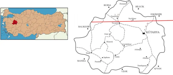
This study was carried out in the concession area of the Western Lignite Facility Directorate, which is located on the Tavşanlı Domaniç highway. Site location map of the study area is given in Figure 1.
Figure 1. Site location map of the study area.
The study areas consist of marl formation. Clay, sandstone and serpentinite distributions can be seen in the marl formation. During the studies, marl was taken as the main rock.
2.2. Current Blasting Applications at the Worksite
In the blasting operations carried out within the scope of this study, pattern change experiments were made using 2 different types of cast boosters. In the blastings, booster sensitive ANFO, emulsion-type dynamite and nitroglycerin-based dynamite as cast booster and nonel delays for hole and surface were used.
First of all, existing hole drilling system in the field and problems were identified. After determining these problems, studies have been done for the solution. Since it is not possible to change the formulation of cast booster, the booster sensitive explosive type was changed. In the existing 8m x 8m x 15m hole pattern, test shots were made by using emulsion type dynamite and nitroglycerin based dynamites. As a result of the trial blastings, it was determined that the problems disappeared. However, since the cost of nitroglycerin-based dynamite is higher than emulsion type dynamite, it has been observed that the amount of muckpile obtained per unit m3 should be increased in order to reduce the costs. For this purpose, the current pattern was designed to be 9m x 9m x 15 m by changing the pattern. In this pattern, test shots were made using nitroglycerin based dynamite and emulsion type dynamite. After each shot, images were taken from the muckpile and grain size analysis was done with WipFrag software. [6] In the light of the data obtained as a result of analyzes, it was examined whether the muckpile had a suitable particle size for loading and transportation with excavators or created additional costs during transportation. As a result of all operations, total cost difference was determined by making a cost analysis.
3. IMPROVEMENT WORK IN THE FIELD
Different problems were observed in the pattern used in the blastings operations before 2017 in the mine. Especially the toe formation problem at the bench floor increased the ripping times and the number of secondary shots. The increase of these shots also caused an increase in terms of costs. The machinery stops operating until the secondary shots are made, and indirectly the working efficiency decreases.
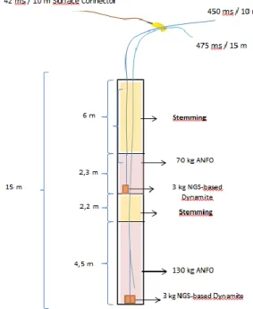
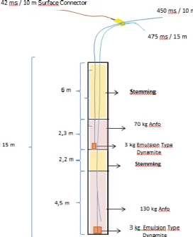
8m x 8m x 15m, 7m x 9m x 15m and 7m x 7m x 15m hole patterns have been tested in the facility before. Drilling and blasting costs have increased as the number of holes to be drilled increases as the distance between the holes and rows increases. To reduce explosive costs, the number of holes and the amount of per unit explosive used should be reduced. In order to reduce the amount of explosives used for the unit work, the distance between the holes and the rows must be increased. A number of cost analyzes were performed on the 9m x 9m x 15m, 9m x 8m x 15m and 10m x 9m x 15m, 10m x 10m x 15m hole patterns. As a result of trial shots, field observations and cost analysis, when the distance between the rows and the holes exceeds 9 meters, problems occur about particle size, the excavators have difficulties in loading and the need arise for pop-shooting process and therefore, it is thought that the most appropriate pattern will be 9m x 9m x 15 meters. Actually, this study has been commenced to determine the most suitable particle size-cost point, and within the scope of this study, holes have been drilled to be 9 meters between holes and 9 meters between rows. Emulsion type dynamite was first used in the drilled holes and another solution was found due to the problems about particle size and hard ridge protrudes at the floor. Emulsion type dynamite and NGS based explosive material were used in the drilled holes. In the trial shots, the specific charge for the 8m x 8m x15m pattern was calculated as 0.208 kg/m3 and the specific drilling was 0.0156 m/m3, the specific charge in the 9m x 9m x 15m hole pattern was 0.165 kg/m3 and the specific drilling was 0.0123 m/m3. The data obtained were compared with the 8m x 8m hole pattern used previously and examined in terms of particle size and cost. Column charge designs of different patterns are given in Figure 2, Figure 3, Figure 4. and Figure 5.
Figure 2. 8m x 8m x 15 m hole pattern, column charge for the use of emulsion dynamite.
Figure 4. 9m x 9m x 15 m hole pattern, column charge for the use of emulsion dynamite.
3.1. Particle Size Analysis
Determination of the particle size in the mining sector is generally used during the process of obtaining the final product. It is not possible to use sieve analysis methods for sizing during quarry production. Instead, image processing software is used.
WipFrag software was used in the image analysis made in this study, and there are many studies in the literature where particle size analyzes were performed with WipFrag software. A scaled object is placed in the muckpile where grain size analysis will be performed. Then the pictures of muckpile are taken and uploaded to the system. The system analyzes the image using different algorithms, and creates a net as an overlay on the original image, which encircles each grain. Depending on the quality of the picture, errors may occur in the process of identifying individual rock fragments. In this case, the user can check the boundaries of the pictures and reach the final result after making the necessary arrangements. [6,8]
One of the most important points to be checked in pattern changes is whether the particle size distribution resulting from blasting is suitable for the need. In terms of blasting economy, it is best to make blasting to obtain muckpile in the grain size ranges suitable for the need. In this study, test shots were made in different patterns and the images of the muckpile obtained were analyzed using WipFrag software. During the application, a ball with 225 mm diameter was used as the scale. Muckpile photos were taken after each shot and during machine operation and the size analyzes were performed with the program (Figure 7 and Figure 8). The data of the shot using NGS Type Dynamite and 8m x 8m x15m pattern is not included in this article due to the high cost, and the data of the shot using the Emulsion Type Dynamite and 9m x 9m x 15m pattern is not included too due to continuation of problems in blasting operations.
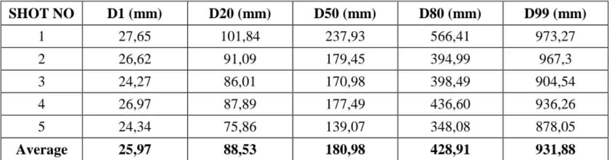
As a result of the analysis, the data obtained from the shot using the 8m x 8m x15m pattern and emulsion type dynamite is given in Table 1, and the data of the shot made by the 9 m x 9 m x 15 m pattern and NGS type dynamite is given in Table 2.
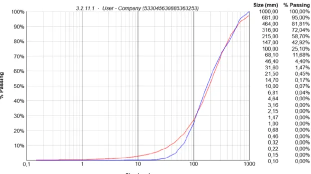
When the results are examined, it is seen that the grain size distribution between the 8m x 8m x 15 m pattern and the 9m x 9m x 15 m pattern shows some differences (Figure 6). However, these differences do not hinder the basic loading and carrying operations. The data obtained from the blastings is of great importance for 3 situations which are loading, transportation and filling of dumping areas. After the pattern change, if a muckpile is formed with oversized boulders and nonhomogenous grain size distribution, the excavators will have difficulty in loading this muckpile and the bucket will not be able to take material so that it is fully loaded. This will inevitably be resulted in the fact that the transport trucks will not homogenously loaded due to very large-sized materials and also increase the transportation costs. One of the basic needs of open pit mining is large dumping areas. Especially, in regions where the lands are valuable and feasible to production later on, the cost of creating new dumping sites for mining increases. Therefore, dumping sites should be created in the most efficient way. If the grain size distributions are not very homogeneous, the fillings to the dumping areas cannot be spread/piled up evenly. In other words, although the site is filled, gaps will remain between them. This will cause inefficient storage in dumping site over time.
In addition, when the capacities and internal dimensions of the buckets of the PH 1900 (10 yd3) and PH 2300 (20 yd3) model excavators used for loading in the facility are examined, it can be seen that even the biggest piece (D99) obtained can be easily loaded.
Table 1. Particle size analysis results of 8m x 8m x15m emulsion type dynamite hole pattern.
Table 2. Particle size analysis results of 9m x 9m x15m NGS type dynamite hole pattern.
Figure 6. Comparison of two different parameters.
D1 D20 D50 D80 D99 8mx8mx15m 25,97 88,53 180,98 428,91 931,88 9mx9mx15m 22,32 108,38 292,63 649,96 1114,75 0 200 400 600 800 1000 1200 Par ticl e S ize (m m ) SHOT NO D1 (mm) D20 (mm) D50 (mm) D80 (mm) D99 (mm) 1 27,65 101,84 237,93 566,41 973,27 2 26,62 91,09 179,45 394,99 967,3 3 24,27 86,01 170,98 398,49 904,54 4 26,97 87,89 177,49 436,60 936,26 5 24,34 75,86 139,07 348,08 878,05 Average 25,97 88,53 180,98 428,91 931,88 SHOT NO D1 (mm) D20 (mm) D50 (mm) D80 (mm) D99 (mm) 1 19,07 83,33 197,88 425,71 970,35 2 23,31 82,6 193,38 430 963,65 3 22,83 102,79 291,34 754,75 1088,4 4 22,83 96,33 346,82 776,98 1353,74 5 23,58 176,89 432,39 862,35 1197,65 Average 22,32 108,38 292,63 649,96 1114,75
Figure 7. WipFrag analysis sample of 8m x 8m x 15m NGS type dynamite hole pattern.
3.2. Dozer Ripping Costs
Dozers are one of the most important auxiliary equipments used in the facilities. Dozers are used for many different purposes. One of these is the ripping process of the toe formed at the bottom and the hard ridge protrudes as a result of the inefficient blasting. Although fuel consumption varies in different sizes and capacities, they generally have an important share in the fuel expenses of the facilities. [7,9] The fuel consumption of the dozers during ripping and other road construction processes etc. has also been measured and in the measurements made, it has been determined that a dozer consumes an average of 38.3 liters/hour in material displacement. Measurements were also made regarding fuel consumption during the ripping process of the same equipment (Table 3). According to the results, it was determined that the dozers consumed 51,7% more fuel during the ripping process compared to the material displacement works (Table 4).
In addition, the dozer provides the work of loosening with the ripper tooth attached to the rock. The ripper tooth is connected to the dozer with the help of a pin. These pins can break due to excessive strain during dozer operation. Unless it is noticed that the pin is broken, the ripper tooth mixes into the loosened soil and becomes difficult to find. If the situation is noticed and the tooth is found, it can then be replaced. Pin breakage and ripper tooth damage are the common problems. While making a cost accounting related to ripping operation, it constitutes an important cost item although they are generally ignored. With the use of NGS based dynamite, the toe problem at the bottom and the hard ridge protrude problem have also decreased. Accordingly, the ripping process has decreased compared to the areas where emulsion type dynamite is used.
Table 3. The amount of fuel consumed during ripping [1].
Survey No Working Hours
(hour)
Fuel Consumed (lt)
Average Fuel Consumption (lt/hour) 1 5 287 57,40 2 4,5 249 55,33 3 3 185 61,67 4 2,5 146 58,40 5 3,5 202 57,71
Average Fuel Consumption 58,10
Table 4. Increase in fuel consumption during ripping [1].
Survey No
Average Fuel Consumption During
Ripping (lt/hour)
Average Fuel Consumption That should be Under
Normal Working Conditions (lt/hour) Increase in Fuel Consumption During Ripping (%) 1 57,40 38,3 49,87 2 55,33 38,3 44,46 3 61,67 38,3 61,02 4 58,40 38,3 52,48
5 57,71 38,3 50,67
Amount of Average Increase 51,70
3.3. Repeating Shots in Areas Where Blasting Efficiency is not Achieved
Records of the repeating shots in the last 5 years are given in Table 5. The decrease in the number of repeating shots is clearly seen in the table.
Table 5. Repeating shot table [1].
Years Number of Shots Number of
Holes Amount of Explosive Used (Kg) Amount of Cast Booster Used (Kg) 2014 10 277 16100 392 2015 9 276 29900 525 2016 9 493 8050 220 2017 5 103 4950 257 2018 2 49 1490 110 3.4. Explosive Costs
200 kg of Anfo and 6 kg of cast booster were used per hole in the trial shots. In order to make an average of 10,000,000 m3 of stripping annually; 10,416 holes should be drilled in the 8m x 8m x 15m hole pattern and 8230 holes should be drilled in the 9m x 9m x 15m hole pattern. Due to the decrease in the number of holes, 437,200 kg less Anfo is consumed in the 9m x 9m x 15m pattern. The costs incurred as a result of the trial shots are given in Table 6.
Table 6. Blasting unit cost table [1]. 8m X 8m X 15m Emulsion Type Dynamite 8m X 8m X 15m NGS Type Dynamite 9m X 9m X 15m Emulsion Type Dynamite 9m X 9m X 15m NGS Type Dynamite Explosive Cost Per Unit m3 (TL/m3) 0.61 0.57 0.42 0.45 Drilling Cost Per Unit m3 (TL/m3) 0.094751563 0.094751563 0.074865432 0.074865432
Labor Cost Per
Unit m3 (TL/m3) 0.10216 0.10216 0.08071 0.08071
Unit Blasting
Cost (TL/m3) 0.8044 0.7701 0.5763 0.6085
4. RESULTS
In this study, drilling and blasting operations in the areas concerned operated by the Western Lignite Facility Mine Directorate were examined. Within the scope of these investigations on drilling and blasting works, it was observed that the problem of toe formation was the leading problem in the facility. Firstly, the type of cast booster was changed. It was determined that the problem of toe
formation decreased after using the cast booster. Within the scope of cost study, changes were made in the hole pattern in order to reduce the costs. In this scope, the hole pattern, which is 8m x 8m, has been rearranged to be 9m x 9m. The muckpile images obtained after the trial shots were analyzed with the WipFrag software.
According to the results obtained;
During the interviews with the operators and the examinations made in the working follow-up forms; it was observed that the ripping work with dozer was reduced in the blastings made by using 9m x 9m x 15m hole pattern and nitroglycerin based dynamite when compared to the blastings made by using 8m x 8m x 15 m hole pattern and emulsion type dynamite. In addition, there have been decreases in the number of repeating shots and pop-shootings. During ripping, a dozer consumed an average of 58,1/hour liters of fuel. This data means, on average, 51,7% more fuel consumption than that of the fuel consumed in normal operation. Considering the amount of stripping done and the hours spent for ripping, the reduction of ripping work provides a good profit to the business.
When the costs of explosives are analyzed, a decrease of 0,196 tl / m3 is observed in costs for per m3. Considering that the annual work is 10 million m3, a 25% financial gain is obtained [1].
The income/savings to be obtained from the blastings made for an average of 10 million m3 of annual stripping is approximately 1,9 million TL. [1] Considering the additional costs due to the differences in grain size distribution, it has been determined that there is an increase in transportation costs of approximately 317686 TL. In addition, reductions in ripping operation and repeating shots caused a reduction in costs. According to these results, it was determined that the 9m x 9m x 15m hole pattern provided an important gain of approximately 1,5 million TL annually to the company. Therefore, It is recommended to continue working with this pattern in order to reduce operating costs.
REFERENCES
[1] Duran, E.,(2019), Garp Linyitleri İşletmesi Sahalarında Yapılan Patlatma İşlemlerinin İyileştirilmesi ve Maliyet Analizi. Kütahya: Dumlupınar Üniversitesi, Fen Bilimleri Enstitüsü, Yüksek Lisans Tezi.
[2] Ceylanoğlu, A., Kahriman, A., Demirci, A., (1993); “Delme-Patlatmanın Önemi, Kullanıldığı Alanlar ve Maden Mühendisliği ile İlgisi”, 1. Delme ve Patlatma Sempozyumu, s. 127-138, Ankara.
[3] Köse, H., Şimşir, F., Onargan, T., Yalçın, E., Konak, G. ve Kızıl, M.S., (2001). Açık İşletme Tekniği, DEÜ Mühendislik Fakültesi Yayınları İzmir.
[4] Bilgin, H. Aydın, Açık İşletmelerde Patlatma Sorunları ve Tasarım, TKİ Gn. Md. ve ODTÜ, Ankara 1986, 102 sayfa.
[5] Hoek, E. and Bray, J.W. (1981) Rock Slope Engineering. Revised 3rd Edition, The Institution of Mining and Metallurgy, London.
[6] Öner, A. (2017). WipFrag Yazılımı ve Kullanımı Üzerine Doğrudan İletişim. Garp Linyitleri İşletmesi, Kütahya.
[7] Kesimal, A. (2009). Delme Patlatma Ders Notları, KTÜ Müh. Fak. Maden Müh. Bölümü, Trabzon
[8] Palangio, T. C., 2000. Using WipFrag to measure, record and predict blast results, 13th Aggregate and Ready-Mixed Concrete Conference, Chiclana, Spain, pp. 1−22
[9] Ersoy, M. ve Ayday, C. (1999). Coğrafi Veri Sistemlerinin Riper Seçimi İşleminde Uygulanması, Afyon Kocatepe Üniversitesi Fen Bilimleri Dergisi, Afyon.
![Table 3 . The amount of fuel consumed during ripping [1].](https://thumb-eu.123doks.com/thumbv2/9libnet/4365945.73240/10.892.138.757.646.831/table-fuel-consumed-ripping.webp)
![Table 6 . Blasting unit cost table [1]. 8m X 8m X 15m Emulsion Type Dynamite 8m X 8m X 15m NGS Type Dynamite 9m X 9m X 15m Emulsion Type Dynamite 9m X 9m X 15m NGS Type Dynamite Explosive Cost Per Unit m 3 (TL/m 3 ) 0.61 0.57 0.42 0.45 Drillin](https://thumb-eu.123doks.com/thumbv2/9libnet/4365945.73240/11.892.137.769.703.938/blasting-emulsion-dynamite-dynamite-emulsion-dynamite-dynamite-explosive.webp)
