Politeknik Dergisi Journal of Polytechnic
Cilt: 8 Say : 1 s. 61-68, 2005 Vol: 8 No: 1 pp. 61-68, 2005
61
Development and Testing of a Cutting Force
Dynamometer for Milling
Süleyman YALDIZ
Mechanical Department, Technical Science College, Selçuk University 42031 KONYA
ABSTRACT
The cutting forces generated in metal cutting have a direct influence on heat generation, tool wear or failure, quality of machined surface and accuracy of the workpiece. In this study, a milling dynamometer that can measure static and dynamic cutting forces by using strain gauge and piezo-electric accelerometer respectively has been designed and developed. The orientation of octagonal rings and strain gauge locations has been determined to maximize sensitivity and to minimize cross-sensitivity. The developed dynamometer is connected to a data acquisition system. Cutting force signals were captured and transformed into numerical form and processed using a data acquisition system consisting of necessary hardware and software running on MS-Windows based personal computer. The obtained results of machining tests performed at different cutting parameters showed that the dynamometer could be used reliably to measure cutting forces. Although the dynamometer was developed primarily for milling operations, it can be used to measure cutting forces during nearly all machining operations (turning, drilling, grinding, shaping etc.).
Keywords: Dynamometer; Strain gauge; Data acquisition; Milling
Frezeleme için bir Kesme Kuvveti
Dinamometresinin GeliAtirilmesi ve
Test Edilmesi
ÖZET
Metal iAleme s ras nda oluAan kuvvetler s oluAumu, tak m aA nmas veya k r lmas , iAlenen yüzeyin kalitesi ve parçan n doCruluCu üzerinde doCrudan bir etkiye sahiptir. Bu çal Amada statik kuvvetleri ölçmek için gerinme ölçerler, dinamik kuvvetleri ölçmek için de piezo-elektrik ivme ölçerin kullan ld C bir frezeleme dinamometresi tasarlanarak imal edilmiAtir. Sekizgen ringlerin ve gerinme ölçerlerin konumu maksimum duyarl l k ve minimum çapraz duyarl l k oluAacak Aekilde belirlenmiAtir. GeliAtirilen dinamometre bir veri toplama sistemiyle birleAtirilmiAtir. Elde edilen kesme kuvveti sinyalleri say sal forma dönüAtürülmüA ve gerekli yaz l m ve donan ma sahip bir veri toplama sistemiyle donat lm A kiAisel bir bilgisayarda iAlenmiAtir. DeCiAik kesme parametrelerinde gerçekleAtirilen testlerden elde edilen sonuçlar dinamometrenin kesme kuvvetlerini güvenilir bir Aekilde ölçebileceCini göstermiAtir. Dinamometre özellikle frezeleme operasyonlar için imal edilmiA olmas na raCmen, hemen hemen tüm öteki kesme iAlemleri için de kullan labilir (tornalama, delme, taAlama, planyalama vs.)
Anahtar Kelimeler: Dinamometre; Gerinme ölçer; Veri toplama; frezeleme 1. INTRODUCTION
Force measurement in metal cutting is essential requirement as it is related to machine part design, tool design, power consumptions, vibrations, part accuracy etc. It is the purpose of the measurement of cutting force to be able to understand the cutting mechanism such as the effects of cutting variables on the cutting force, the machinability of the work piece, the process of chip formation, chatter and tool wear (1). It has been observed that the force values obtained by engineering calculations contain some errors compared to experimental measurements. Since the undeformed chip thickness and the direction of cutting speed vary at every moment, cutting process in milling is geometrically complex. Owing to such complexity, the cutting forces
even in steady state conditions is affected by many parameters and the variation of cutting force with time has a peculiar characteristic (2). The need for measurement of all cutting force component arises from many factors, but probably the most important is the need for correlation with the progress of tool wear (3). If this can be obtained, it will be possible to achieve tool wear monitoring in milling based on force variation. Another reason for the cutting forces measurement is that it is a good indicator in detecting tool wear. It is well known that during the cutting process, the cutting parameters such as cutting speed, feed rate and depth of cut often present a deviation from the calculated values.
The strain gauge produces a clear relation between the measured quantity and the strain on a
Süleyman YALDIZ / POLGTEKNGK DERGGSG, CGLT 8, SAYI 1, 2005
62
suitable spot on the spring element (4). In most cases, the static force is obtained by a strain gauge type sensor which produces an output voltage proportional to elastic deformation.The cutting force dynamometers must be manufactured at sufficient accuracy and high rigidity, and particularly suitable for dynamic loads (5). Ito et al. (6) designed some strain gauge based dynamometers that can be adapted to some machine tools and defined the criterions of their rigidity and sensitivity. In designing dynamometer, some principles such as parallel beam type (1, 7), circular hole (8, 9, 10), piezo-electric (11, 12), etc., have been used widely.
This study outlines a strain gauge based octagonal-ring type analogue dynamometer design and
prototyping. This dynamometer is capable of measuring three-force components. As the reading of analogue values manually is a difficult and tedious job, a computer connection for data acquisition has been realized.
2. MECHANICAL DESIGN OF THE DYNAMOMETER
2.1. Design Criterions and Material of Dynamometer
Sensitivity, rigidity, elasticity, accuracy, easy calibration, cost and reliability in the harsh cutting environment have been taken into account in designing the dynamometer. Dimensions, shape and material of dynamometer are considered to be effective factors on dynamic properties of the dynamometer.
A dynamometer essentially consists of an important ring element. The rigidity, high natural frequency, corrosion resistance and high heat conductivity factors were taken into consideration while selecting the ring materials. Also, deformation under the load should conform to that of strain gauges (13).
In this study, AISI 4140 steel, which meets above requirements, was selected as the ring material. The properties of this material are given in Table 1.
Table 1. Properties of AISI 4140 steel
Yield strength Modulus of elasticity Poisson ratio Hardness 550-900 N/mm2 210000 N/mm2 0.3 217 HB
2.2. Determination of Dimensions of the Octagonal Rings
The thickness t, radius r, and width of the circular strain ring b are the three basic controllable parameters that affect the rigidity and sensitivity. Since there is no effect of ring width b and modulus of elasticity (E) on the strain per unit deflection, bmin can be
taken as 30 mm to set up the rings securely (5).
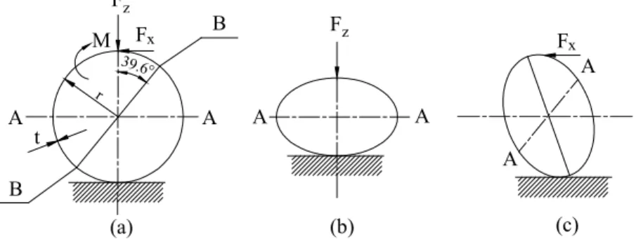
The deformation of circular ring under the effect
of thrust force Fz and main cutting force Fx separately
are shown in Fig. 1b and 1c respectively. As long as strain on A and B where the strain gauges are going to be fixed (Fig 1a) are within the elastic limits of the ring material, the strain and deflection due to the main cutting force should be considered for the purpose of the ring design for maximization of sensitivity ( x/Fx) and
stiffness (Fx/ x).
The strain gauges should be placed where the stress concentration has maximum value. The experiments have shown that good results are obtained for octagonal rings when the inclined gauges are at points 450from the vertical instead of 39.60required by
the circular ring theory.
The strain per unit deflection can be expressed as (5):
1.09
0.61
/
1.8
z zt
t
r
=
r
r
(1)where z is the deflection in a radial direction and zis
the strain due to thrust force Fz. It is clear that for
maximum sensitivity and rigidity z/ zshould be as large
as possible. This requires that r should be as small as possible and t as large as possible. But small r brings some difficulties in mounting the internal strain gauges accurately. Therefore, for a given size of r and b, t
(a) (b) (c) 39.6° M F F A A A A A B B r t F F A z x x z
DEVELOPMENT AND TESTING OF A CUTTING FORCE DYNAMOMETER FOR MGL…/ POLGTEKNGK DERGGSG, CGLT 8, SAYI 1, 2005
63
should be large enough to be consistent with the desired sensitivity. Ito et al. (6) performed a finite element analysis for the elastic behaviour of octagonal rings. They expressed that the octagonal ring is substantially stiffer than the circular ring when t/r equals 0.05 or less, the difference in displacement of circular ring and octagonal ring is less than 10% if t/r equals 0.25 or greater. In order to be consistent with this expression, the ring thickness and ring radius were taken as 8 mm and 32 mm respectively. Thus, the rate of t/r (8/32) provides corresponding sensitivity to stiffness ratio/( /r) for octagonal ring.
2.3. Verifying The Dimensions of Octagonal Rings
The maximum expected force, which the rings may face in each direction, is assumed as 5000 N. If the cross sectional dimensions of a curved bar is smaller than the radius of the centre line, it is considered to be thin ring (14). Taking into account dimensions as seen in Fig. 2. (b=30 mm; r=32 mm; t=8 mm), elastic strains z
and Xdue to forces Fz and Fxare calculated according
to ring theory by using the following equations (7, 8).
4 2
1, 09
4.32 10
z zF r
x
Ebt
= ±
=
(2) 4 22,18
8.7 10
x xF r
x
Ebt
= ±
=
(3) b t rFig. 2. Octagonal dynamometer ring dimensions
The stress occurring on rings caused by thrust and main cutting forces can be calculated by placing elastic strain ratio values in Eq. (4, 5) as follows:
2 90.8 N/mm z =Eez = (4) 2 181.7 N/mm x=Eex= (5)
As AISI 4140 steel was used for manufacturing the ring and its yield strength is 550-900 N/mm2, the
calculated stress values ( z and x) occurring on the
rings are within safety limits for this material.
The results of calculation for stress are within the elastic limit of ring material. For an analysis purpose, the dynamometer has been considered as a mass supported by a spring elements, as shown in Fig. 3.
F m k t e e
Fig. 3. Free-body diagram of the developed dynamometer
The following empirical expression for k gives a better estimation than the derived equations from thin ring theory. The effective stiffness
k
e and effective mass me are given as follows, respectively by Shaw (5)and Tse et al. (15):
39375 N/mm 40 e Ebt k r = = (6) 17 52.26 kg 35 e r h m =m + m = (7)
where mris the mass due to radial force and mhis the
vibrated mass.
The natural frequency of such a system (fn-cps)
can be calculated as 1 138.1 cps 2 e n e k f m = = (8)
In order the recorded force not to be influenced by any vibration motion of the dynamometer, its natural frequency must be at least four times larger compared to the frequency of exciting vibration (5).
As long as the strains at A and B are within the elastic limit of strain ring (see Fig. 1), the strain varies linearly to the force, and so the ring satisfies the desired requirement of linearity. The mean deflection at A in strain ring (Q) is calculated as:
/
e0.127 mm
F k
=
=
(9)2.4. Construction of The Three-Component Milling Dynamometer
It is desirable that the dynamometer must be able to measure cutting forces without any interference. For this purpose, a three-component dynamometer employing four octagonal rings between two plates was designed and constructed. In order to prevent a hysteresis problem and to tighten the rings with pre-loading, the ring surfaces that contact the plates were machined as concave. The surfaces of the ring that strain gauges are bonded should be ground (Ra=3-10 µm) to be normal to the strain direction (16). The details of the rings are shown in Fig. 4.