SYSTEMS-LEVEL QUALITY IMPROVEMENT
Received: 26 June 2016 / Accepted: 24 October 2016 / Published online: 5 November 2016 # Springer Science+Business Media New York 2016
Abstract This article proposes the employment of a propor-tional valve that can calculate the amount of oxygen in the air to be given to patient in accordance with the amount of FiO2
which is set from the control menu of the ventilation device. To actualize this, a stepper motor-controlled proportional valve was used. Two counts of valves were employed in order to control the gases with 2 bar pressure that came from both the oxygen and medical air tanks. Oxygen and medical air manom-eters alongside the pressure regulators were utilized to perform this task. It is a fuzzy-logic-based controller which calculates at what rate the proportional valves will be opened and closed for FiO2 calculation. Fluidity and pressure of air given by the
ventilation device were tested with a FlowMeter while the oxygen level was tested using the electronic lung model. The obtained results from the study revealed that stepper motor controlled proportional valve could be safely used in ventila-tion devices. In this article, it was indicated that fluidity and pressure control could be carried out with just two counts of proportional valve, which could be done with many solenoid valves, so this reduces the cost of ventilator, electrical power consumed by the ventilator, and the dimension of ventilator.
Keywords Proportional valve . FiO2. Medical air .
Manometer . Fuzzy logic control . Stepper control
Nomenclature
FiO2 Fraction of Inspired Oxygen
SLPM Standard Liter Per Minute
LPM Liter Per Minute
SCPV Stepper Controller Proportional Valve I2C Inter Integrated Circuit
Introduction
FiO2, which is the oxygen concentration during mechanical
ventilation, can take in the ventilator a value between %21 and %100 [1]. In this study, proportional valve was used in order to adjust the oxygen level provided to patient. Many research groups, whose aims were the accomplishment of ventilation, oxygenation, elimination of CO2and control of temperature,
proposed various ventilator prototypes. Volume controlled ventilation is the most commonly recommended type. However, the pressure also must be kept within certain limits for safety in the volume controlled ventilators. This is because high inspiratory pressure may cause barotrauma and excessive negative expiratory pressure may lead to impairment in air-ways. Numerical modelling (evaluation of gas transfer occa-sions) is essential for designing respiratory support devices and optimize their performances [2]. Fluidity, oxygen concen-tration and pressure control can be conducted in such a way that will not give a chance to any extreme case by means of a proportional valve used in the prototype which was prepared for this study.
Since no mathematical model is needed in the fuzzy logic control that is thought to be as an alternative to PID control This article is part of the Topical Collection on Systems-Level Quality
Improvement. * Adem Gölcük [email protected] İnan Güler [email protected] 1
Vocational School of Technical Sciences, Department of Computer Technologies, Karamanoğlu Mehmetbey University,
Karaman, Turkey
2 Faculty of Technical Education, Electronics and Computer
Education, Gazi University, Ankara, Turkey DOI 10.1007/s10916-016-0650-y
The Use of Stepper Motor-Controlled Proportional Valve for Fio
2
Calculation in the Ventilator and its Control with Fuzzy Logic
method and that is also effective in the control of nonlinear systems, this control method was started to be used in indus-trial applications [3]. The proportional valve used for this study is a DC stepper motor controlled valve. It is the readily-prepared fuzzy logic based controller which deter-mines at what rate this valve will be opened and closed.
According to Dalton’s law, the pressure of a mixture of non-reacting gases (such as air) is the sum of individual pres-sures of its each component (partial pressure) and the contri-bution of every component to total pressure equals to volu-metric proportion of that component. If this law is applied to the air, the latter volumetrically contains 78 % nitrogen (N2), 21 % oxygen (O2), and 0.03 % carbondioxide (CO2).
The gas given to patient for respiration has a mixture of medical air and O2. FiO2 calculation in this study was
c o nd u c t e d in a c co r d an c e wi t h Da l t o n’s law and Amagat’s law of partial volumes. The rest of this work organized as the following: electronic circuit design is explained in Section 2, the designed fuzzy-logic based controller and rule base are explained in Section 3, results and discussion are explained in Section 4, and finally the conclusion is given in Section 5.
The designed ventilator
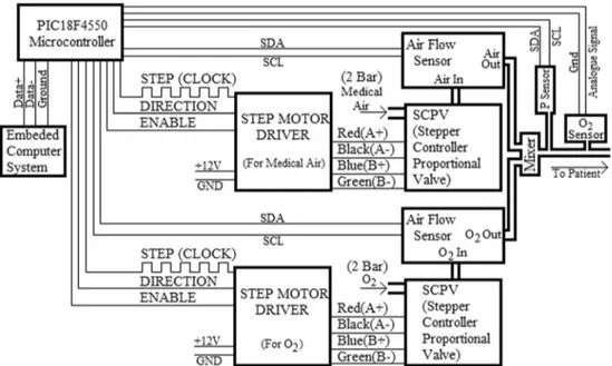
The block diagram of ventilator designed for this study is shown in Fig. 1. Sensors, valves, microcontroller, etc., used in the design of ventilator device, were indi-cated individually in the block diagram, connection types were shown and these were explained in detail between Section 2.1 and Section 2.7.
Stepper controller proportional valve
A proportional valve was used to adjust the fluidity control of gases that come from the oxygen and medical air tanks, the volume and pressure of air to be given to patient from the ventilator and the FiO2proportion. Two counts of SCPV-1-3
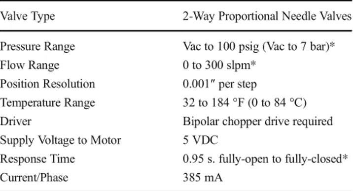
valve, produced by the Clippard Company, were employed for this purpose. As shown in Fig.1, a DC stepper motor driver was used to turn these valves on or off position. DC motors were the first practical device to convert electrical energy into mechanical energy [4]. The fuzzy-logic-based controller cal-culates at what rate the valves will be opened and closed. The amount of oxygen and medical air passing through the valves is adjusted by switching the valves on or off position step by step. Technical specifications of this valve are given in Table 1 [5].
The valve has an input and an output port. According to Table1, a maximum of 7 bar pressure can be applied to input port. This valve can be used in hospitals where the pressure of oxygen and medical air given to the input of ventilator is a maximum of 6 bars [5]. The values of lung volume and lung capacities are shown in Fig.2[6,7].
Inspiratory Capacity (IC) refers to the maximum amount of air that can be taken into the lungs, starting from a normal expiration level. This value can mount to a maximum of 3500 ml [6, 7]. Technical specifications given in Table 1 shows that SCPV valve makes it possible to have a control of air flow up to 300 l per minute. According to these data, maximum respiration rate that can be taken by this valve can be calculated as 300 L/3,5 L≈ 85. Average respiratory rate of a healthy person ranges from 10 to 20 per minute. Respiratory rate may increase in cases such as coronary failure, pneumo-nia, ARDS (Acute Respiratory Distress Syndrome) [8]. Van
Fig. 1 Block diagram of the designed ventilator
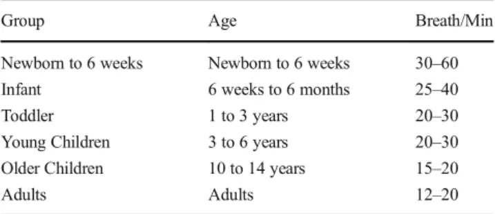
Kaam AH et al. observed the respiratory rate as 41 ± 14 breaths/min on HFV(High-frequency ventilation) ventilator which coupled in the newborn intensive care units [9]. When the data sheets of present ventilators are examined, it is seen that the respiratory rate is 2-80 bpm in terms of breath/ min. Respiratory rates by age group are provided in Table2. Considering these values, it can also be said that SCVP valve is suitable for respiration rate. As it is also obviously seen in Table2, it becomes more of an issue regarding patients’ health to carry out respiration control with an adjustable system. In this study, it was provided with a stepper motor controlled microcontroller-based proportional valve control where pa-tients were given oxygen at more accurate rates.
Table3shows the values read from the AirFlow sensor in every step of SCVP valve. When these values are analyzed, it turns out that valve sensitivity (0,001^per step) is very conve-nient for respiratoy settings, too. These values were taken into consideration while identifying the membership functions of fuzzy-logic-based controller.
Embedded computer system
The software prepared for the ventilator and the fuzzy-logic-based controller, and software prepared for the control of pro-portional valves run inside the embedded computer. These
softwares were prepared with Java programing language. The results produced by the fuzzy- logic-based control-ler are transmitted to PIC18F4550 microcontrolcontrol-ler via USB port and the valves are switched on and off in line with the calculated values. The values which micro-controller reads from the oxygen, pressure and airflow sensors are also transmitted to the embedded computer system via USB port and these values are used by the ventilator software.
PIC18F4550 microcontroller
It is a microcontroller that is produced by the Microchip Technology Company and makes use of RISC (Reduced Instruction Set Computer) architecture and has a USB support. USB is one of the most commonly used communication modes. Data transmission via USB is carried out through 4 lines. The red wire carries 5 V signals, black wire 0 V, green wire data and the white wire carries CLK (Clock) signals. USB communication uses syncronous serial communication protocol [12]. The communication between the embedded computer system and PIC18F4550 microcontroller is con-ducted via USB port.
PIC18F4550 microcontroller sends signals to DC stepper motor drivers according to values calculated by the fuzzy-logic-based controller inside the embedded system and thus valves are switched opened and closed at the desired rate. So, the gas of oxygen and medical air mixture is given to patient in accordance with the amount of FiO2 adjusted from the
ventilator.
Microcontroller also reads data from the oxygen, pressure and AirFlow sensors. The oxygen sensor used for this study produces analog signal. ADC specification of the microcon-troller was utilized to read data from the oxygen sensor. On the other hand, pressure and AirFlow sensors produce digital sig-nal. I2C communication protocol was used in order to read data from these sensors with microcontroller. Hence, the Table 1 Technical specifications of SCPV-1-3 valve
Valve Type 2-Way Proportional Needle Valves Pressure Range Vac to 100 psig (Vac to 7 bar)*
Flow Range 0 to 300 slpm*
Position Resolution 0.001″ per step Temperature Range 32 to 184 °F (0 to 84 °C)
Driver Bipolar chopper drive required
Supply Voltage to Motor 5 VDC
Response Time 0.95 s. fully-open to fully-closed*
Current/Phase 385 mA
Fig. 2 Lung volume capacities. (Tidal Volume-TV = 500 mL, Inspiratory Reserve Volume-tRV = 3000 mL, Expiratory Reserve Volume-ERV = 1100 mL, Residual Volume-RV = 1200 mL, Inspiratory Capacity-IC = 3500 mL, Functional Residual FRC = 2300 mL, Vital Capacity-VC = 4600 mL, Total Lung Capacity-TLC = 5800 mL)
connection between the microcontroller and these sensors are indicated with SDA and SCL lines in Fig.1.
Microcontrollers require some simple peripheral circuits when they are used for circuit designs. For example, power supply is used to supply required energy for both microcon-troller and its neighboring circuits [13–16]. Power supplies must be isolated from mains and have a limited current and voltage output in order to protect the patient. Switch mode power supply provides further advantages for the isolation between the mains and human body [16,17].
Oxygen sensor
Oxygen sensor measures the percentage of oxygen in the air which is given to the patient. KE-25 series oxygen sensor, produced by Figaro Company, was used in this study.
Technical information related to this sensor is provided in Table4[18].
This sensor generates an analogue outcome between 0 V and 63 mV as an output. This data were firstly given to INA122 instrumentation amplifier and then amplified to a voltage between 0 V and 5 V. The structure of this integrated circuit is shown in Fig.3[18,19].
In order to amplify the voltage level from 63 mV to 5 V, the the gain should be;
G¼ 5 V
.
63 mV¼ 79:37
RGresistor in Fig.3is calculated as;
RG¼ 200 K .
79:37−5
ð Þ ¼ 2:69KOhm:
Data cables came from the oxygen sensor were connected to 2nd and 3rd pins of INA122 in Fig.3. The output voltage (V0) on the 6th pin was connected to the 2nd pin of
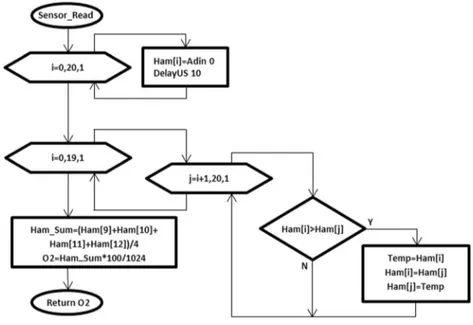
PIC18F4550 microcontroller. This pin is the 0th analog con-vertor (AN0) of the microcontroller and the 0th pin of Port A [20]. The software in order to read data from the microcon-troller and oxygen sensor was written in the language of Proton Basic and its flow diagram is given in Fig.4.
As it also appears in the flow diagram in Figs.4, 21 counts of data are consecutively read by the microcontroller from the oxygen sensor and saved to BHam^ sequence variable. A
Table 3 The values read from AirFlow sensor in every step of SCVP
Step Air Flow Step Air Flow Step Air Flow Step Air Flow Step Air Flow
0 0 20 5,58 40 12,37 60 19,37 80 26,53 1 0,22 21 5,91 41 12,7 61 19,62 81 26,83 2 0,39 22 6,25 42 13,07 62 20,06 82 27,23 3 0,56 23 6,56 43 13,38 63 20,35 83 27,54 4 0,82 24 6,91 44 13,82 64 20,7 84 28,02 5 1,08 25 7,23 45 14,05 65 21,08 85 28,42 6 1,34 26 7,61 46 14,46 66 21,49 86 28,76 7 1,6 27 7,91 47 14,79 67 21,86 87 29,12 8 1,92 28 8,26 48 15,18 68 22,24 88 29,43 9 2,18 29 8,6 49 15,45 69 22,58 89 29,93 10 2,59 30 8,95 50 15,85 70 22,96 90 30,15 11 2,86 31 9,27 51 16,21 71 23,31 91 30,54 12 3,24 32 9,65 52 16,56 72 23,69 92 30,94 13 3,55 33 9,93 53 16,87 73 23,93 93 31,4 14 3,92 34 10,25 54 17,24 74 24,41 94 31,79 15 4,17 35 10,6 55 17,62 75 24,68 95 31,02 16 4,45 36 10,98 56 17,94 76 25,05 96 32,33 17 4,68 37 11,32 57 18,27 77 25,32 97 32,65 18 4,95 38 11,68 58 18,62 78 25,72 98 33,07 19 5,24 39 11,99 59 19,02 79 26,17 99 33,59 100 34,01 Table 2 Range of respiration rates [10,11]
Group Age Breath/Min
Newborn to 6 weeks Newborn to 6 weeks 30–60
Infant 6 weeks to 6 months 25–40
Toddler 1 to 3 years 20–30
Young Children 3 to 6 years 20–30
Older Children 10 to 14 years 15–20
digital filter is applied for these data with the subsequent nested i and j loops. For the digital filter, data read through theBSelection Sort^ algorithm are sorted in ascending order. Arithmetic mean of 9th, 10th, 11th and 12th elements of this sorted sequence is calculated and the values being read are made consistent. Oxygen percentage of air given to patient is calculated with the command of O2 = Ham_Sum * 100/1024. Being calculated, the amount of O2 is again feedback to the main program. The main program of microcontroller sends the resultant value to the embedded computer system via USB port.
Digital air flow sensor
Air flow sensor was used to measure the volume of the air given to patient. A total of 3 counts of these sensors were used; one for the outlet of oxygen valve, the other for the outlet of medical air valve and another one for that of the expiration valve. The fuzzy-logic-based controller adjusts the oxygen rate in the air being delivered to the patient. It firstly processes the data
conveyed from the AirFlow sensors and then computes at what rate the SCVP valves needs to be turned on or off. No change is done in the SCVP valves if the value read in the AirFlow sensor is a target value. AirFlow sensors used in this study can measure the flow of air and oxygen up to 200 l per minute. This sensor converts the measured values into a 2 bytes digital outcome. Digital pressure sensor
A pressure sensor was used to measure the pressure of air given to patient. When the air reaches the value adjusted from the ventilator, the inspiration is terminated. The pressure sen-sors used in this study can measure the gas pressure up to 15PSI = 1054.60cmH2O. This sensor also measures the
tem-perature of air that is given to patient. This sensor converts the measured values into a 4 bytes digital outcome. 2 bytes data is for pressure and the other 2 bytes is for temperature.
Pressure regulator
Before it is given to the ventilator, high pressure gas that comes from the oxygen and air tanks is reduced by the ma-nometer to a pressure between 4.5 and 6 bar in the hospitals. In order to obtain more sensitive results, the pressure of gases that came from the tanks was lowered to 2 bar by the pressure regulator used in the ventilator. Thus, the pressure applied to the inlet of the ventilator was made fixed and more sensitive results were observed in the outlet of proportional valves.
Designed fuzzy-logic-based controller
Fuzzy logic works well in order to define the uncertainties in the process variable. In addition to this, fuzzy logic control can be designed without mathematical modeling. It can overcome local optima to reach global optima. Fuzzy logic theory is a general mathematical approach that allows partial mem-berships. Several studies have shown fuzzy logic control to be an appropriate method for the control of complex processes [16, 21–23].
Table 4 Figaro KE-25 oxygen
sensor technical information [18] Long life 5 years
Measurement range 0 ~ 100 % O2
Accuracy (Note 1) ±1 % (full scale)
Operating conditions Atmospheric pressure 811 hPa ~1216 hPa
Temperature 5 ~ 40 °C
Relative humidity 10 ~ 90%R.H. (no condensation)
Unaffected by CO2, CO, H2S, NOx, H2
Application fields Medical - Anesthetic instruments,
respirators, oxygen-enrichers
Response time (90 %) (Note 4) 14 ± 2 s
Hardware
The fuzzy-logic-based controller designed for this study steps in during the inspiration and opens the SCVP valves at desired rate. The fuzzy controller calculates according to values ad-justed from the ventilator how many steps the valves must be opened to carry out the inspiration and then valves are opened in line with these values. If the valves had been opened step by step without using the fuzzy controller, the microcontroller would have read data from the oxygen, pressure and airflow sensors in every step of the valves and the USB would have communicated with the embedded system. Thus, it would have prevented the inspiration process from occurring at de-sired rate and sensitivity. A block diagram of implemented AirFlow feedback fuzzy-logic-based controller is shown in Fig.5. This controller is used to manage SCPV valves that adjust the flow of both the medical air and O2. Valves are
simultaneously switched on and off in order for the mixture to be homogenous.
Fuzzy membership function
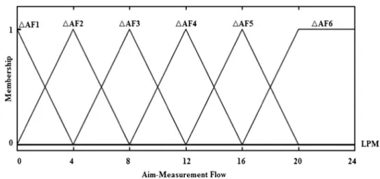
Input membership function of fuzzy-logic control system is shown in Fig.6. Input membership function ranges between 0 LPM and 24 LPM and was identified as the difference be-tween the intended and measured fluidity. The fuzzy-logic-based controller uses this input membership function so as to determine how many steps the proportional valve must be opened. This input membership function was used to control the flow of both the Medical Air and O2.The measured
flu-idity equals to the amount of Medical air or O2read from
the AirFlow sensors in terms of Liter/Minute. The intended fluidity is the amount of O2 or Medical air in
Fig. 4 Flowchart of the developed software to read data from the O2 sensor with microcontroller
terms of Liter/Minute which is calculated to make up the mixture of the air to be given to patient.
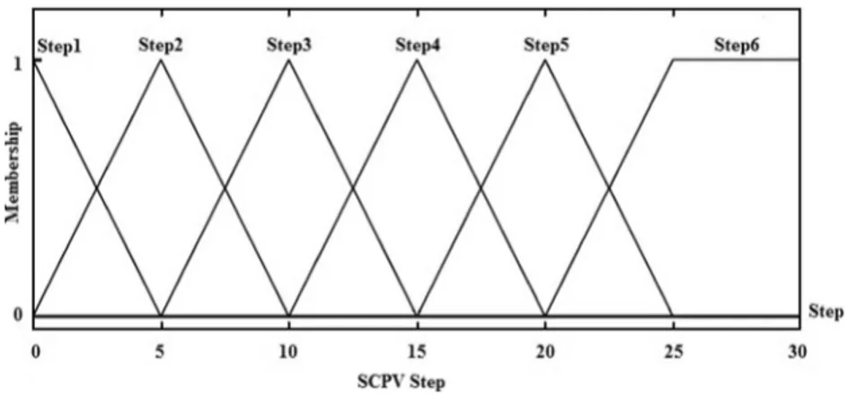
Figure7displays the output membership function prepared for the fuzzy controller. The output membership function in-cludes the step information for SCVP between 0 and 30. This function is utilized to determine how many steps SCPV valve, used for both O2and Medical air inspiration, will be opened.
After the inspiration process is over, SCVP valves are closed till the end. Then the expiration solenoid valve is switched on so that the patient can discharge his/her breath.
A rule base was made up with the IF-THEN fuzzy rule for the fuzzy-logic-based controller. These rules were used, just as in the input and output membership functions, to control both the Medical Air SCVP valve and O2SCPV valve.
1st Rule: If (Aim-MeasurementFlow is ΔAF1) then (SCPV Step is Step1)
2nd Rule: If (Aim-MeasurementFlow is ΔAF2) then (SCPV Step is Step2)
3rd Rule: If (Aim-MeasurementFlow is ΔAF3) then (SCPV Step is Step3)
4th Rule: If (Aim-MeasurementFlow is ΔAF4) then (SCPV Step is Step4)
5th Rule: If (Aim-MeasurementFlow is ΔAF5) then (SCPV Step is Step5)
6th Rule: If (Aim-MeasurementFlow is ΔAF6) then (SCPV Step is Step6)
Calculation of gas mixture for O2and medical air
Amagat’s law of partial volumes can be defined as, Bpartial volume of an individual gas in a gas mixture equals to the sum of its volume and multiplication of mole fraction of that gas; and the total volume is equal to the sum of partial volumes of individual gases^. Ideal mixture molar volume is the result of well-known Amagat’s law of additive volumes [24].
Accordingly, the mixture formula in the eq.1was utilized to calculate the oxygen level (FiO2) in the air given to patient.
FiO2 100 ¼ PeakFlow−O2Flow ð Þ:21 100 þ O2Flow PeakFlow ð1Þ
The term 21/100 in Equation (1) refers to the level of O2
within the Medical air.
FiO2: It is the oxygen percentage of air to be given to
patient and doctors determine the desired rate from the control panel of ventilator. This is a value between 0 % and 100 %.
PeakFlow: It is the inspiration peak flow in terms of Liter/ Minute (LPM) that needs to be given to patient. Doctors determine this value from the control panel of the venti-lator. PeakFlow is the sum of mixture of Medical Air and O2that is given to patient.
O2Flow: It is the amount of O2in terms of Liter/Minute
that needs to be given to patient according to FiO2and
PeakFlow values adjusted from the control panel of the ventilator. In order to calculate this value, Equation (1) was edited as in that of Equation (2).
O2Flow¼
PeakFlow: FiOð 2−21Þ
79 ð2Þ
After O2Flow was calculated, the amount of Medical Air
and O2that needs to be given to patient was calculated using
the formula in Equation (3).
AirFlow¼ PeakFlow−O2Flow ð3Þ
Using the values calculated with the formulas2and3, the fuzzy logic controller calculates how many steps SCVP valve, used for Medical Air and O2, needs to be opened during the inspiration.
Fig. 6 Input membership function (LPM-Liter Per Minute)
Inference mechanism and purification
In fuzzy-logic-based controllers, input functions and rule b a s e w e r e p r o c e s s e d w i t h M a m d a n i I n f e r e n c e Mechanism and fuzzy results for step SCPV was pro-duced. For defuzzification, in other words the conver-sion of these fuzzy results into numerical results, COG (center of gravity) approach was used because our out-put function, step SCPV value is to be numerical results rather than fuzzy results as they will be used to regulate the ventilator.
Results and discussion
Results
It has become more diffficult to test medical devices as the complexity of hardware and software has increased. Digital
models are more comprehensive testing methods in compari-son to physical models. The advantage of a digital model is that it is flexible enough to obtain wide ranges of peripheral scripts, which isn’t always possible when a physical model is used [25]. The lung model, which had a FlowMeter and an oxygen sensor, AirFlow and a Pressure sensor, was used in order to test the study conducted.
The flow and pressure of air given to patient was measured with FlowMeter. The FlowMeter used for this testing process and a computer connection is shown in Fig. 8. Oxygen amount of air given to patient was mea-sured with the oxygen sensor. PIC18F4550 microcon-troller was used to read data from the oxygen sensor as in the ventilatotion device in Fig. 1. Data read from the sensors by the microcontroller was transmitted to computer and then results were observed.
An example is given concerning the eqs.1and2. Sample ventilator settings: When it is FiO2 = 50 ve
PeakFlow = 30LPM;
Fig. 8 Testing Process with FlowMeter Fig. 7 Output membership
O2Flow is calculated as O2Flow = 30.(50–21)/
79 = 11,013 LPM.
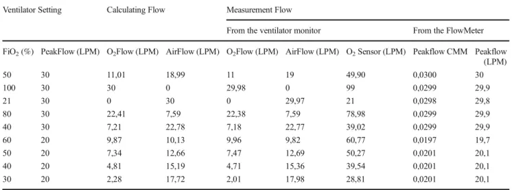
Results obtained from the lung model are given in Table5. It also provides data read by the flow sensors and oxygen sensor that were used for the ventilation device.
Discussion
The values given in the conclusion part are the results that were read from the designed Electronic Lung Model and mon-itor of the ventilation device. The designed device will be tested on real patients after the requisite certificates for med-ical device clinic research (e.g CE certification) and research ethics committe approval are obtained. Results obtained from the pre-established lung simulation appear to be quite success-ful. Many solenoid valves with different orifice widths are used in the present ventilation devices to control the fluidity of air to be given to patient. Out of the solenoid valves gener-ally having orifice widths of 5LPM, 6LPM, 15LPM and 40LPM, more than one solenoid valve is used for the control of both the medical air and oxygen. In some ventilation devices, fluidity of air to be given to patient is adjusted by continuously swithching on/off the solenoid valve, which both increases the cost and leads the ventilator to consume more energy.
As can also be seen in Table1, the proportional valve is triggered by a power of 385 mA. Now that solenoid valves are usually turned on/off with a power of 2A, it turns out that the proportional valve used is very advan-tageous with respect to energy. The job that is done by all these solenoid valves was carried out with two counts of proportional valve in the designed ventilation device. This method enabled to more sensitively calculate the values of air given to patient.
Conclusion
Using a stepper motor controlled proportional valve, a new ventilation device was put forward in this study to adjust the level of FiO2and fluidity of air to be given to patient. A
mechanical ventilation device was designed in line with this purpose. The fuzzy logic controller calculates how many steps the proportional valves must be opened for the mixture of medical air and oxygen that will be given to patient according to FiO2and PeakFlow settings adjusted from the ventilation
device. The results calculated by the fuzzy controller are trans-m i t t e d t o trans-m i c r o c o n t r o l l e r v i a U S B p o r t a n d t h e Microcontroller turns the proportional valves on or off through the stepper motor driver. Digital Flowmeter ve Digital Lung model were utilized to test the study conducted. The results of the conducted tests were saved and given in Table5. These results have indicated the usability of the de-signed system.
Acknowledgments This study is supported by Tübitak 2211-C Scholarship with reference number 1649B031402604.
References
1. Bordes, J., Erwan, d.A., Savoie, P.H., Montcriol, A., Goutorbe, P., and Kaiser, E., FiO2 delivered by a turbine portable ventilator with an oxygen concentrator in an austere environment. J. Emerg. Med. 47(3):306–312, 2014.
2. Bonfanti, M., Cammi, A., and Bagnoli, P., Gas transfer model to design a ventilator for neonatal total liquid ventilation. J. Emerg. Med. 37(12):1133–1140, 2015.
3. Köse, F., Kaplan, K. and Ertunç, H. M. , PID ve Bulanık Mantık ile DC Motorun Gerçek Zamanda STM32F407 Tabanlı Hız Kontrolü. Otomatik Kontrol Ulusal Toplantısı, TOK2013, 26–28 Eylül 2013, Malatya, 2013.
Table 5 Fluctuating FiO2 Values and O2Flow, AirFlow, PeakFlow and O2 Values Calculated and Measured According to PeakFlow Settings Ventilator Setting Calculating Flow Measurement Flow
From the ventilator monitor From the FlowMeter FiO2(%) PeakFlow (LPM) O2Flow (LPM) AirFlow (LPM) O2Flow (LPM) AirFlow (LPM) O2Sensor (LPM) Peakflow CMM Peakflow
(LPM) 50 30 11,01 18,99 11 19 49,90 0,0300 30 100 30 30 0 29,98 0 99 0,0299 29,9 21 30 0 30 0 29,97 21 0,0298 29,8 80 30 22,41 7,59 22,38 7,59 78,98 0,0299 29,9 40 30 7,21 22,78 7,18 22,77 39,02 0,0299 29,9 60 20 9,87 10,13 9,96 9,82 60,77 0,0197 19,7 50 20 7,34 12,66 7,47 12,69 50,27 0,0201 20,1 40 20 4,81 15,19 4,71 15,36 39,54 0,0201 20,1 30 20 2,28 17,72 2,01 17,98 28,81 0,0201 20,1
4. Siemens Training Education Program, STEP 2000 Series,BBasics of DC drives and related products^,http://cmsapps.sea.siemens. com/step/pdfs/dc_drives.pdf, Access Date:01.03.2016.
5. Clippard Instrument Laboratory, Inc.,BTechnical Data Bulletin 3 . 1 1^, h t t p : / / w w w. c l i p p a r d . c o m / d o w n l o a d s / P D F _ Documents/Product%20Data%20Sheets/Clippard%20SCPV%20 Proportional%20Valve.pdf, Access Date: 17.03.2016.
6. Köse, B., The effect of low tidal volume management in oxy-genation and breathing parameters on one -lung ventilation. Thesis, Istanbul University / Faculty of Medicine / Surgery D e p a r t m e n t / D e p a r t m e n t o f A n e s t h e s i o l o g y a n d Reanimation, Istanbul, 2009.
7. Shier, D., Butler, J. and Lewis, R. , Hole’s Human Anatomy and Physiology. Eleventh Edition, 13 978-0-07-282953-2 ISBN-10 0-07-282953-2, 2007.
8. Janik, P., Janik, M.A., and Wróbel, Z., Integrated micro power frequency breath detector. Sensors and Actuators, A: Physical. 239:79–89, 2016.
9. van Kaam, A.H., Rimensberger, P.C., Borensztajn, D., De Jaegere, A.P., and Group, N.S., Ventilation practices in the neonatal inten-sive care unit: a cross-sectional study. J. Pediatr. 157(5):767–771 , 2010.e763
10. Redmond, C. (2013). Trans-thoracic impedance measurements in patient monitoring. EDN Network.
11. Stillwell, S. B. (2006). Mosby’s critical care nursing reference. Elsevier Health Sciences.
12. Başçiftçi, F., and Eldem, A., An interactive and multi-functional refreshable braille device for the visually impaired. Displays. 41: 33–41, 2016.
13. Celik, B., Güler, N.F., and Güler,İ., Design and realization of a microcontroller based E-test strip application device. Instrum. Sci. Technol. 37(6):676–682, 2009.
14. Kapıdere, M., Ahıska, R., and Güler, İ., A new microcontroller-based human brain hypothermia system. J. Med. Syst. 29(5):501– 512, 2005.
15. Kapidere, M., Müldür, S., and Güler,İ., Control of dental prosthesis system with microcontroller. J. Med. Syst. 24(2):119–129, 2000. 16. Gölcük, A., Işık, H., and Güler, İ., Design and construction of a
microcontroller-based ventilator synchronized with pulse oximeter. J. Med. Syst. 40(7):180, 2016.
17. Koçer, S., Canal, M.R., and Güler,İ., Design of low-cost general purpose microcontroller based neuromuscular stimulator. J. Med. Syst. 24(2):91–101, 2000.
18. Figaro K. E.,http://www.sos.sk/a_info/resource/c/figaro/KE_ series_technical_info.pdf, Access Date: 23.06.2016
1 9 . I N A 1 2 2 , h t t p : / / p d f . d a t a s h e e t c a t a l o g . c o m / d a t a s h e e t / BurrBrown/mXrvxxv.pdf, Access Date:23.06.2016
2 0 . P I C 1 8 F 4 5 5 0 , h t t p : / / w w 1 . m i c r o c h i p . c o m / d o w n l o a d s / en/devicedoc/39632c.pdf, Access Date:23.06.2016
21. Işik, H., and Saraçoğlu, E., The design of thermoelectric footwear heating system via fuzzy logic. J. Med. Syst. 31(6):521–527, 2007. 22. Kilic, Y.A., and Kilic, I., A novel fuzzy logic inference system for decision support in weaning from mechanical ventilation. J. Med. Syst. 34(6):1089–1095, 2010.
23. Saraoğlu, H.M., and Şanlı, S., A fuzzy logic-based decision support system on anesthetic depth control for helping anesthetists in sur-geries. J. Med. Syst. 31(6):511–519, 2007.
24. Sagdeev, D.I., Fomina, M.G., Mukhamedzyanov, G.K., and Abdulagatov, I.M., Measurements of the density and viscosity of 1-hexene + 1-octene mixtures at high temperatures and high pres-sures. Thermochim. Acta. 592:73–85, 2014.
25. Miller, B., Vahid, F. and Givargis, T., Digital mockups for the test-ing of a medical ventilator. Proceedtest-ings of the 2nd ACM SIGHIT international health informatics symposium, ACM, IHI’12, January 28–30, 2012, Miami, 2012.
![Fig. 3 Structure of INA122 [19 INA122]](https://thumb-eu.123doks.com/thumbv2/9libnet/4555348.82986/5.892.75.435.710.1048/fig-structure-of-ina-ina.webp)