Controller Design for a Limited Angle Torque Motor
and dsPIC Implementation
İlhami Çolak Faculty of Engineering and
Architecture Istanbul Gelisim University
Istanbul, Turkey [email protected]
Murat Sahin
Roketsan A. S. Mechatronic Design Department Ankara, Turkey [email protected]Semih Çakıroğlu
Roketsan A. S. Mechatronic Design Department Ankara, Turkey [email protected]Zafer Esen
Roketsan A. S. Mechatronic Design Department Ankara, Turkey [email protected]Abstract: This study addresses the modeling of a LAT motor in Simulink environment and then designing and testing various controllers for this model. The LAT motor model is first expressed using equations which describe the DC motor dynamics. Then a simulation model is created using these equations. The non-linear part stemming from the limited torque angle of the motor is also added to the model. PID and cascaded PID controllers are designed for the model using classical design methods and parameters satisfying the design criteria are calculated. For testing the controllers on hardware using a real LAT motor, the controller codes are generated using Embedded Coder and embedded on a dsPIC microcontroller. The test data are then analyzed and the controller performances are evaluated. Keywords: LAT motor, PID control, cascaded control, dsPIC controller implementation
I. INTRODUCTION
DC motors are heavily used as actuators in systems with position controllers. They are used in systems ranging from robotics to industrial positioning. In mechatronic systems comprising position control, precision, repeatability and fast response times are a must [1]. To satisfy these requirements, limited angle torque (LAT) motors are also used. They are suitable for applications with mechanical angular limits. With their low volume, short response times and low inertia, they are preferred and used in aerospace and optics [2, 3]. As they have direct actuation capability, LAT motors don’t need any transmission mechanism; so they allow more precise control and a volume advantage over traditional motors with transmission [3]. Some of the researches done about LAT motors are given below.
Y.Zhang and co. created a non-linear model of a LAT motor and they compared simulation and test results. They observed that the non-linear model approached the experimental results more closely [4]. Du Chunyang and co. used optimal control algorithms to drive a LAT motor in an optical scanning system. They used a DSP during their experiments [2]. F.S. Ahmed and co. used the LuGre friction model to obtain a non-linear
was suitable for modeling the mechanical dynamics of the motor [3].
In this study, position control of a LAT motor using various controller structures is done. A LAT motor is first chosen and modeled in MATLAB Simulink environment. Using the Control System Toolbox various controllers are designed. Control systems are evaluated using the motor model in MATLAB and controller parameters satisfying the requirements are obtained. Then an experiment system is prepared in the laboratory consisting of the modeled LAT motor and a dsPIC based controller and motor driver card. The controllers are tested using this setup and the data are saved. Lastly the results are compared and the control system which best satisfies the requirement is determined.
The usage of mechatronic systems are increasing by the development in DC motor technology. In recent years DC motors are preferred in some applications which need high power and high velocity rather than hydraulic and pneumatic systems because of their easy maintenance, easy usage and low cost properties.
In mechatronic systems LAT motors are in charge of translating electrical energy to the mechanical energy. Mechanical work comes true after triggering the motor by the control system and the new mission is defined by the feedback from the first work. Basic block diagram of a mechatronic system is given in Figure 1. In this diagram process can be either the missile system or a medical tool.
II. LATMOTOR MODEL
As the LAT motor is a DC motor, its electrical equation can be expressed as: [5]
The mechanical equation of the motor can be expressed as:
J
T t
JT t
B
J
(2)
Where θ is the rotor position, J is the rotor inertia, B is the viscous friction coefficient, T is the motor torque and T is the load torque.Combining these equations the transfer function of rotor position with an input voltage is can be expressed as:
(3)
where K is the torque constant [6].
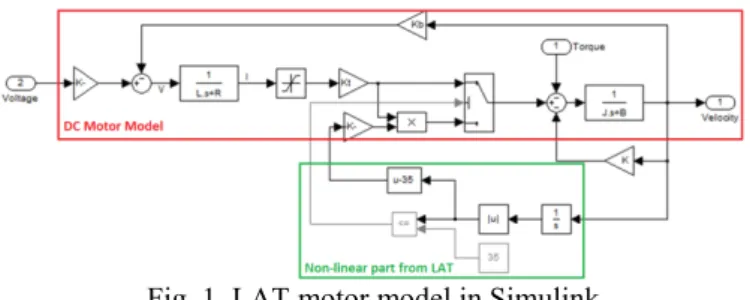
The limited angle of the motor was also considered in the model, and the model is built in Simulink environment as shown below in Fig. 1.
Fig. 1. LAT motor model in Simulink
The DC motor model is presented in the model as shown in the red rectangular part, and the non-linearity coming from the LAT motor is modeled as shown in the green part. As the motor torque starts to fall after the rotor moves away from the zero point by 35°, this non-linearity is modeled using a switch.
III. POSITION CONTROL SYSTEMS
In feedback control systems design, the analysis of the open loop system is crucial for understanding how the closed loop system will behave. [7] In this regard, one of the most preferred methods is creating the root-locus curve and its analyzing it [8]. To obtain the root-locus curve, first the system transfer function must be obtained.
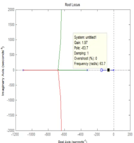
The root locus curve is calculated using (3) and the obtained graph is given below in Fig. 2.
Fig. 2. Motor open-loop root-locus graph
As can be seen in the figure, the system has a total of three roots consisting of one root at origin, a second one near the origin (-285) and a third further one (-1115). The third root shows the electrical dynamics, the second root mechanical characteristics and the root at the origin shows the effect of the added integrator. The root coming from the electrical dynamics is much further than the one coming from the mechanical dynamics, thus mechanical dynamics will be much more dominant in the position response. A bandwidth of 10 Hz (63 rad/s) is determined as the requirement of the closed loop controller. The controller designs are done using this criterion.
Three controllers are designed to control the system: • A PID position controller (Pos. controller),
• A cascaded PID position – velocity cascaded controller (Pos. Vel. controller),
• A position – velocity – current cascaded controller (Pos. Vel. Cur. controller).
A. Position Controller
The popular PID controller given in (4) is used as the main controller.
1
(4)
E(s) is the error between the reference position command and the measured position. As can be seen, the controller adds two zeroes and a root to the system. Both of the zeroes can be positioned to the left or the root, or one of them can be placed on each side. As the zeroes shift to the left, the roots approach the imaginary plane and increase oscillation in the response. [9] The final system obtained by placing the roots and zeroes is given below in Fig. 3. The output of the Pos. controller is motor voltage. -5000 -4000 -3000 -2000 -1000 0 1000 2000 -4000 -3000 -2000 -1000 0 1000 2000 3000 4000 Root Locus
Real Axis (seconds-1)
Im agi nar y A xi s (s ec onds -1)
Fig. 3. Pos. controller closed-loop root B. Position-Velocity Cascaded Controller A cascaded controller system consisting of control loop and an inner velocity control controller block diagram is given below in Fi
Fig. 4. Pos. Vel. controller block d The position controller requirements requirements. The velocity loop should be d bandwidth is theoretically at least two times its outer loop. In practice however it’s bett that it has at least five times the bandwidth o that the inner loop will not limit the dynamic Increasing the bandwidth of the velocity lo result in a very fast velocity response, b increase the effect of disturbance cause quantization errors. [10] Considering thes bandwidth of the velocity loop controller is Hz.
The root-locus graphs for the velocity contr position control system are given below in respectively.
-locus graph
f an outer position loop is used. The ig. 4.
diagram
are the system designed so that its
s the bandwidth of ter to design it so of its outer loop, so cs of the outer loop. oop too much will but this will also ed by noise and se limitations, the determined as 100 roller and the final Fig. 5. and Fig. 6
Fig. 5. Root-locus graph
Fig. 6. Pos. Vel. controller As can be seen in the figure, origin, so a PI controller is r error. The PI controller would zero to the real axis. As part of velocity loop prevents the controller is satisfactory. A P c that the outer loop bandwidth is C. Position-Velocity-Current C In addition to the velocity co previous section, a current con system which uses the phase makes it possible to control an the system too. The block d controller system is given below
-1200 -1000 -800 -600 -300 -200 -100 0 100 200 300 R Real A Im agi nar y A xi s ( sec onds -1) -3500 -3000 -2500 -2000 -15 -2500 -2000 -1500 -1000 -500 0 500 1000 1500 2000 2500 Real A Im a gi na ry A x is ( sec onds -1)
h of the velocity controller
closed-loop root locus graph , there aren’t any routes at the
equired to prevent steady state d add a root at the origin and a f the position control loop, as the steady state error, only a P controller gain is determined so s 10 Hz.
Cascaded Controller
ontroller loop mentioned in the ntroller loop is also added to the e current as its feedback. This
nd limit the current dynamic of diagram of the Pos. Vel. Cur.
w in Fig. 7. 0 -400 -200 0 200 Root Locus Axis (seconds-1) 500 -1000 -500 0 500 1000 System: sysPVC Gain: 85 Pole: -38.3 + 51.5i Damping: 0.597 Overshoot (%): 9.67 Frequency (rad/s): 64.2 Root Locus Axis (seconds-1)
The bandwidth of the current controller loop is set to 500 Hz as to be 5 times the velocity controller loop. To design the controller, first the equation between the motor voltage and motor current is obtained as shown in (5).
(5)
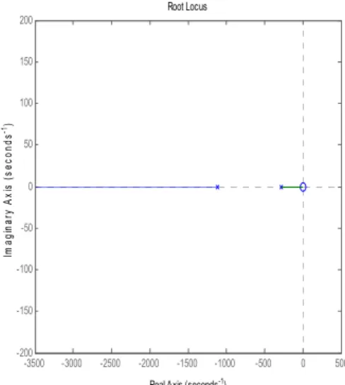
where is the motor current, is the motor voltage, is the motor inertia, is the viscous friction, is the motor phase inductance, is the motor phase resistance, is the back-EMF constant and is the torque constant.The system consists of a zero which is very close to the origin and two roots. A PI controller must be used to prevent the steady state error. The PI controller will add to the system a root at the origin and a zero in the real axis. The root-locus graph of the current controller is given below in Fig. 8.
Fig. 8. Root-locus graph of the current controller The velocity loop consists of three roots and a zero away from the origin. Again as the system doesn’t have any free roots, a PI controller must be used to prevent steady state error. The PI controller will add a root at the origin and a real zero. At the required bandwidth, a simple P controller as the position controller is satisfactory. The root-locus graph for the final controller system is given below in Fig. 9.
Fig. 9. Pos. Vel. Cur. controller closed-loop root locus graph IV. HARDWARE IMPLEMENTATION AND DATA ACQUISITION
The test and data acquisition setup architecture is given below in Fig. 10.
Fig. 10. Test and data acquisition setup architecture The setup consists of three main parts. The first part is the LAT motor and an absolute position sensor assembly. The second part is an electronics card which drives the LAT motor, reads motor phase current and the absolute position sensor data, and outputs all of this data using RS-485 communication. The final part is the computer which is used for collecting and analyzing the data. The test setup is as shown below in Fig. 11.
-3500 -3000 -2500 -2000 -1500 -1000 -500 0 500 -200 -150 -100 -50 0 50 100 150 200 Root Locus
Real Axis (seconds-1)
Im agi n ar y A x is ( s ec o nds -1) -2 -1.5 -1 -0.5 0 0.5 1 x 10⁴ -1.5 -1 -0.5 0 0.5 1 1.5x 10 4 Root Locus
Real Axis (seconds-1)
Im ag inar y A xi s ( sec onds -1)
Fig. 11. Test and data acquisition setup
The controller algorithms are implemented on the motor driver card using the code generated from Simulink by Embedded Coder. The controller code is merged with the other firmware which handles the communication, motor drive and data acquisition. Then the resulting code is embedded into the dsPIC which is used as the microcontroller on the card.
V. COMPARISON OF SIMULATION AND EXPERIMENTAL RESULTS
The three controllers are implemented on the test hardware and experimental results consisting of position, velocity and current measurements are collected in real time. Two reference signals are applied. The first one is a step command with an amplitude of 10 degrees. The second reference signal is a 10 Hz sine wave with an amplitude of 10 degrees.
The position responses of the three controllers for the step command are given below in Fig. 12.
Fig. 12. Comparison of position responses, step command In standard DC motors, although not always suitable in every
velocity and current dynamics to the system using cascade controllers is seen to be improving the controller rigidity according to the measurements. It can be seen in Fig. 12 that the controller with the current feedback has also the fastest response and best settling characteristics.
The velocity and current responses of the three controllers for the step command are given below in Fig. 13 and Fig. 14 respectively.
Fig. 13. Comparison of velocity responses, step command
Fig. 14. Comparison of current responses, step command It can be seen in Fig. 13 and Fig. 14 that the Pos. controller has the highest oscillations and as a result the highest power requirements. In the Pos. Vel. Cur. controller the velocity is observed to be faster and has some oscillations compared to the Pos. Vel. controller, but this also allows the faster response time in the position response.
The power requirements of the Pos. Vel. and Pos. Vel. Cur. controllers are roughly the same; however the Pos. Vel. Cur. controller requires slightly more current as it has a faster response.
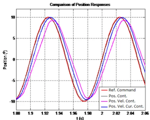
The position responses of the three controllers for the sine wave signal reference are given below in Fig. 15.
Fig. 15. Comparison of position responses, sine wave reference
It can be seen in the figure above that when a sine wave reference signal is applied as the command, Pos. controller also has an acceptable response. The Pos. Vel. controller is seen to have less bandwidth then the other two controllers. The velocity and current responses of the three controllers for the sine wave reference are given below in Fig. 16 and Fig. 17 respectively.
Fig. 16. Comparison of velocity responses, sine wave reference
Fig. 17. Comparison of current responses, sine wave reference The velocity and current responses are roughly the same in all three controllers, when a sine wave reference signal is applied as the input.
VI. CONCLUSION AND FUTURE WORKS
In our study, the model of a LAT motor is implemented using its mathematical model in a simulation environment and three controllers are designed. First, the controller parameters are calculated in the simulation environment and then they are implemented and evaluated using test hardware.
As the experimental results show, the Pos. Vel. Cur. controller has the best overall performance considering the step and sine wave reference commands. The Pos. Vel. controller has the least oscillations, but falls short on bandwidth. The Pos. controller, although has good response characteristics when a sine wave reference is applied, has too much oscillations and a steep current demand when a step reference command is applied.
APPENDIX
Motor parameters for the motor are given below:
2.8 . , 0.021 /
21.2 . / , 7 Ω, 5 ACKNOWLEDGMENTS
Authors would like to thank Roketsan Co. for their financial support in this work.
REFERENCES
[1] N. Bacac, V. Slukic, M. Puškaric, B. Štih, E. Kamenar, S. Zelenika, “Comparison of different DC motor positioning control algorithms”, MIPRO 2014, 26-30 May 2014.
[2] Du Chunyang, Li Tiecai, Cao Zhengcai, “Accurate Tracking Control of a Limited Angle Torque Motor”, Industry Applications Conference, 38th IAS Annual Meeting, 12-16 Oct. 2003
[3] F. S. Ahmed, S. Laghrouche, M. El Bagdouri, “Nonlinear modeling of Pancake DC Limited Angle Torque Motor based on LuGre friction model”, Vehicle Power and Propulsion Conference (VPPC), 1-3 Sept. 2010
[4] Y. Zhang, I. R. Smith, and J. G. Kettleborough, “Performance Evaluation for a Limited-Angle Torque Motor”, IEEE/ASME Transactions On Mechatronics, Vol. 4, No. 3, Sept. 1999
[5] Nicolae Patrascoiu, "Modeling and Simulation of the DC Motor Using Matlab and LabVIEW*",Int. J. Engng Ed. Vol. 21, No. 1, pp. 49-54, 2005. [6] Kiruthika, A., Rajan, A.A., Rajalakshmi, P., "Mathematical modelling and speed control of a sensored brushless DC motor using intelligent controller", Emerging Trends in Computing, Communication and Nanotechnology (ICE-CCN), 2013
[7] Constantine H. Houpis, Stuart N. Sheldon, “Linear Control System Analysis and Design with MATLAB®, Sixth Edition (Automation and Control Engineering)”, 2013.
[8] Katsuhiko Ogata, "Modern Control Engineering (5th Edition)", Prentice Hall; 5 edition, September 4, 2009.
[9] Benjamin C. Kuo, Farid Golnaraghi, “Automatic Control Systems”, September 6, 2002.
[10] Monteiro, J.R.B.A., Pereira, W.C.A., Santana, M.P., Almeida, T.E.P., Paula, G.T., Santini, I., “Anti-windup method for fuzzy PD+I, PI and PID controllers applied in brushless DC motor speed control”, Power Electronics Conference (COBEP), 2013 Brazilian.