Selçuk J. Appl. Math. Selçuk Journal of Vol. 7. No. 1. pp. 45-61, 2006 Applied Mathematics
Landmark detection via ANN for A Web Based Autonomous Mobile Robot: SUNAR
Nihat Yılmaz1, Seref Sa˘gıro˘glu2, Mehmet Bayrak1
1Department of Electrical - Electronics Engineering, Faculty of Engineering-Architecture,
Selcuk University, Konya, Turkey
e-mail: nyilm az@ selcuk.edu.tr , [email protected]
2 Department of Computer Engineering, Faculty of Engineering-Architecture Gazi
University, Ankara, Turkey e-mail: ss@ gazi.edu.tr
Received: January 18, 2005
Summary. In this study, a landmark detection method was developed for finding or position correction of a web based mobile robot designed and im-plemented for long term and regular scientific purposes. Colored numeric and alphanumeric character sticker in place of other artificial landmarks appropri-ate for robot is selected to be landmark for understanding of both human and robot. Statistical analysis of captured and segmented image part is used for feature vector extraction. Statistical properties of histogram, projections and image raw data are selectable components of feature vector. The feature vector is tested by previously trained multilayer perceptron feed forward neural net-work (ANN). For this aim, online programs required for robotic activities, image processing and neural network processes have been developed on web interface of web-robot. In this program, improved software libraries for SUNAR system are employed. Real time results and robot scenes are monitored online on web portal.
1. Introduction
Mobile robots have many types in practice such as wheeled, legged and flying used in a wide range of areas [1]. Legged mobile robots are used to lumber in forestry areas and to explore volcanoes. Wheeled mobile robots are employed for cleaning, safety and/or carriage tool at home and offices. Flying mobile robots are used to explore in military and civilian areas in order to get reliable informa-tion about atmospheric layers for weather forecast. Mobile robots are also very
popular for entertainment and movie sectors such as sumo wrestling, football matches and dangerous scenes filmed. A figment of imagination creatures are also livened up with mobile robots too. Wheeled mobile robot designs are still popular because of their energy saving advantage and facility of implementation on different fields [1]-[9].
Most control systems on mobile robots are performed by computers because of their complicated operations to be handled by human operators. Improving the comfort of human operator is always required. Connecting the mobile robots to computer system via wireless devices helps human operator to handle and to control mobile robot within large distances efficiently and effectively [2]. This type of mobile robots is known as tele-robot and usually used in unsafe and dangerous areas for human beings, for example in exploration of aerospace and volcanoes [3, 4]. Recent developments in technology help to improve mobile robots providing high speed and cost effective communication techniques. Web based mobile robots have been employed in robotic lectures [5], museums and art galleries [6].
All of mobile robots need navigation systems, if they are designed for autonomic usage. For the successful navigation, mobile robots must robustly carry out a few tasks such as object detection and avoidance, path planning, map building and self localization [10]. Among them, self localization, which is the estimation of its current localization with respect to a map, is an important and difficult function. Landmark recognition is an important component of a mobile robot system. It is used to compute and correct vehicle position with respect to a map [11]. Landmarks are divided into two classes; natural or artificial. The methods using natural landmarks are more general approaches than those using artificial landmarks.
In this study, a landmark detection system developed for SUNAR (Selcuk Uni-versity Application Robot) was presented. SUNAR is a web based mobile robot designed for general purposes and controlled via WAN and LAN communication [12]-[14].
The landmark system is based on classification feature vectors extracted from captured images by using ANN. Feature vector consists of invariant moment values calculated from red pair of captured image.
In this work, red colored numeric and alphanumeric character sticker in place of other artificial landmark appropriate for robot was selected to be landmark for understanding both human and robot. Four different landmarks having similar properties were recognized. Recognition system is independent of direction, size and point of view of landmarks. These landmarks are required at basic navigation studies for educational usage of SUNAR. Although, there is more capable feature extraction system at SUNAR, only invariant moments of raw image data are used in this work.
The following parts of the paper are organized as follows. Section II describes structure of web based mobile robot: SUNAR. Section III details vision system of SUNAR and Landmark detection. Finally, experimental results and conclu-sions are outlined in Section IV and V respectively.
2. Web Based Mobile Robot: SUNAR
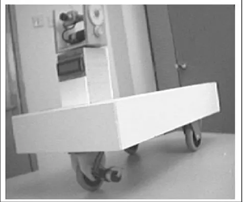
In this study, a web based mobile robot depicted in Fig. 1 was presented. The mobile robot was especially designed for web-based distance control for various applications. The robot system consists of communication center and mobile robot. The communication center handles the internet connection of the mobile robot. The mobile robot consists of microcontrollers, a camera system, portable PC with Wi-Fi LAN Adapter, motors and motor drives for movements of vehicle and camera, and speed sensors for calculating the position of it. The robot is a three-wheeled robot. Rear wheels are free. Front wheel steers and drives the mobile robot. For the simplicity and the cost concern, all body of SUNAR is constructed from PVC (Polyvinylchloride) and polyethylene materials.
Figure 1. SUNAR developed
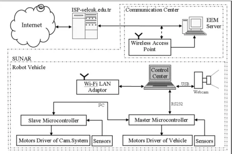
Two microcontrollers (PIC16F877) were used in hardware implementation as shown in block diagram of SUNAR (Fig. 2). The slave microcontroller controls
camera system, motors and sensors. It provides communication with master microcontroller via 2 serial bus. Master microcomputer manages vehicle mo-tion control, communicamo-tion with portable PC and slave microcontroller. The master microcontroller is connected to portable PC via RS232 port. In addi-tion, four DC motors with gearbox, four optical tachometers coupled to the dc motors, four H-bridges for DC motor driving and two LCDs are used for this implementation. The control center manages all activities in the robot vehicle.
Figure 2. Block diagram of SUNAR presented in this work
Detailed information about the vehicle motion system, the camera system and communication system and control center are given in following sections sequen-tially.
2.1. Hardware of Web-SUNAR A. Vehicle motion system
Drive system of SUNAR consists of a DC motor with gearbox and transmission components of movement parts using gears and shafts. There are two optic tachometers coupled to DC motor with gearbox made by FAULHABER Com-pany.
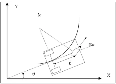
Figure 3. Kinematics model of SUNAR
Kinematics equations of SUNAR are given in equations (1)-(6). The kinematics equations for the rear wheel are:
(1) ˙= cos cos
(2) ˙= sin cos
(3) ˙ =
sin
Kinematics equations for the front wheel are:
(4) ˙ = cos( + )
(6) ˙ = sin
Positioning of SUNAR is calculated by the master microcontroller using equa-tions (1)-(6). Controlling posiequa-tions for vehicle and camera motion systems are achieved by PID controllers. These controllers are individually run on master and slave microcontrollers.
B. Camera Motion System
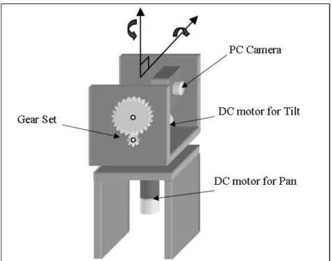
Camera motion system is illustrated in Fig. 4. Camera motions are provided with two DC motors. The motors turn 360 horizontally (pan) and 270 ver-tically (tilt). Motion coming from the first DC motor is transferred to the platform with a gear so that horizontal pan motion is provided. Motion coming from the second DC motor tilts the platform vertically via a gear set. The DC motors are driven with PWM based H-Bridge DC motor drivers controlled by PIC16F877.
Figure 4. Designed camera motion system
Three types of communications have been achieved between the control center-master microcontroller, wireless access point-Wi-Fi LAN adaptor and center- master-slave microcontroller. The first communication between control center and in-ternet service provider (ISP) is realized in wireless by using a wireless access point and Wi-Fi LAN Adapter. Communication range is expanded to 1 km by using external active antenna. The second communication between the control center and the master microcontroller is provided through RS232 port in the form of Modbus ASCII, 19200 Baud, 8 bit and odd parity. Finally, communi-cation between master and slave microcontroller is enabled through I2C serial port.
D. Control Center
The control center consists of a portable PC compatible with IBM on SUNAR, a control program running on this computer and communication units. The specification of the computer is Intel Centrino 1.6 GHz microprocessor, 512 MB RAM, 30 GB HDD and internal Wi-Fi LAN adapter. The control center realizes the following six functions;
(1) Web server: publishing web portal for internet users of SUNAR
(2) Program interpreter and video server: running of written image based robot program through web. Monitoring desired online results created by running program steps
(3) Telecontrol, response for immediate commands coming from web user, de-termining of system status:
(4) Communication and determining of vehicle position: Managing the commu-nication with mobile robot and calculates the position of mobile robot from the information encoder.
(5) Vision based autonomous or semi-autonomous robot control: Processing the images and extracts knowledge from images for a human operator or au-tonomous robot control algorithm.
(6) Application development: possibility of application development through web is granted to admin and other users utilizing provided software libraries. 2.2. Software Developed
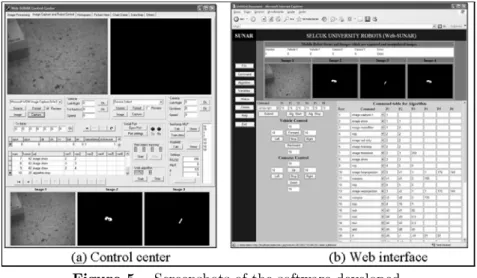
In this study, the developed software consists of three programming parts in-cluding microcontrollers, control center, and the web interface. The microcon-trollers are programmed using MPLAB assembler programming. Programming the web application is based on PHP for database and JavaScript for timing and refreshing functions. Delphi is used for the control center. The image capturing and the serial communication are done via the third party component. The screenshots for the control center and web interface are given in Fig. 5.
Figure 5. Screenshots of the software developed.
SUNAR mainly consists of two parts as shown in Fig. 1. Important controls are achieved in the control center. So there has been heavy communication between master microcontroller and control center. The control center helps to achieve simple and complex tasks. Simple tasks are to turn right or left, to move backward or forward, to adjust speed of camera and vehicle motions. Complex tasks are based on autonomous study such as wall and line tracking, object tracing, localization and finding landmarks. These tasks can be loaded to the control center via a web page on internet. All task commands are firstly stored to the system database and then executed. This reduces the process time and consequently simplifies the simultaneous execution of several tasks. While one task continues the other starts so enough time is required to distinguish the tasks. Status of tasks is also stored to the database. It needs to be emphasized that all complex tasks are realized by the control center. The other part of SUNAR is the communication center. This center provides internet connection of the robot. It consists of a web server and a wireless access point. In this server, Windows XP based standard server programs are run.
As shown in Fig. 5, the program menu for the control center consists of the database, the status of UDP port, the serial port controls, the image capturing, the speed control of camera and the vehicle for manual usage, the calculated positions for the camera and the vehicle. In addition, two menu buttons (“Op-tion”, “Image Processing”) also exist on the control center program. “Image Processing” menu is used for the image processing covering the filtering, seg-mentation, moment functions and recognition for the vision system as described in Section 2.6. “Option” menu provides a smooth control and communication utility covering the parameters.
The web interface has manual control of the options for the database, the cap-tured images, the speed control of camera and the robot vehicle, the commands
of semi-autonomous usage and the vehicle positions.
3. Vision system of SUNAR and Landmark detection
This system is designed for further analysis such as navigation, recognition, observation, detection, path finding and estimation. Mobile robot navigation in a natural environment calls for a sophisticated sensory system. A method for visual landmark recognition is also used for both positioning and navigation in this paper. We define positioning as a process that uses the sensory input of the robot to derive the location and orientation of the robot with respect to a map of the environment. Image source is a webcam on the mobile robot. The webcam is connected to portable PC via USB port. The captured image is RGB color image in 320x240 resolutions.
3.1. Searching Landmark
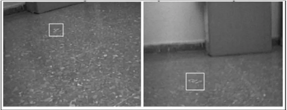
The captured image is scanned via variable size according to searching windows for red and green colored landmark. The searching process can be done for different tilt angle of cameras as shown in Fig.6. A histogram-based scanning algorithm is used in this work. Details of the algorithm will be explained in a subsequent article.
Figure 6. Screenshot of landmark scanning process 3.2. Pre-Processing and Feature Extraction
In this study, after finding landmark roughly, landmark image is passed through preprocessor. The preprocessor unit consists of median filter, histogram equal-izations, and threshold. Thus, this image part is ready for feature extraction process. There are a lot of alternatives that consist of image raw data, his-togram, projections and statistical properties of these for feature extraction process. In this paper, invariant moment values of image raw data is used. Equations of invariant moments are given in equations (12)-(18)
(7) = X =0 X =0 ( )
(8) = X =0 X =0 ( − )( − ) ( ) (9) = 10 00 = 01 00 (10) = 00 (11) = + 2 + 1 (12) 1= 20+ 02 (13) 2=¡20− 02¢2+ 4211 (14) 3= ¡ 30− 312 ¢2 +¡321− 03 ¢2 (15) 4=¡30− 12¢2+¡21− 03¢2 (16) 5= ¡ 30− 312 ¢ ¡ 30+ 312 ¢ h¡ 30+ 312 ¢2 − 3¡21− 303 ¢2i ¡ 321− 03¢(21+ 03)£3(30+ 12)2− ( 21+ 03)2 ¤ (17) 6= ¡ 20− 302 ¢ h¡ 30+ 12 ¢2 −¡21+ 303 ¢2i +4¡30− 12¢(21+ 03) (18) 7= ¡ 312− 30 ¢ ¡ 30+ 12 ¢ h¡ 30+ 12 ¢2 − 3¡21+ 303 ¢2i ¡ 321− 03¢(21+ 03)£3(30+ 12)2− ( 21+ 03)2 ¤
Seven features are extracted for red, green and blue colors by using invariant moment equations. These values are used to be input for neural network recog-nition units.
3.3. Neural network based recognition
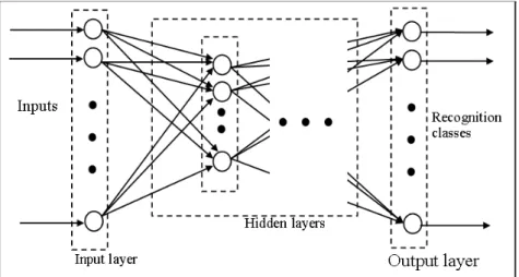
In this study, feed forward multi layer perceptron artificial neural network struc-ture is used for landmark recognition. For this purpose, neural network libraries designed for SUNAR are used. The neural network is trained with back prop-agation training algorithm. While training “loadnet”, “builtnet”, “initnet”, “testnet” commands are used and test steps of neural network are implemented on the web. Furthermore, for stand-alone usage, a program named as “Nerony” has been developed using Delphi.
Figure 7. Structure of ANN used in this work.
The cost function utilized in back-propagation algorithm is in a squared error form as given by Eg.4
(19) () = 1 2 0 X =1 2()
where () represents the instantaneous cost function at iteration , () is the error from the output node at iteration and 0 represents the number of output nodes [10]. The error is defined for each output node as,
(20) () = () − ()
where () is the desired response of the output node at iteration and () is the output of the output node at iteration [15]
A. Initialization
Set all the weights and threshold levels of the NN to small value that dis-tributed random numbers.
B. Forward Computation
Training example is denoted by [x(n), d(n)] , []: input vector, []: desired response vector. The internal activity level () () for neuron in layer is given by (21) () () = X =0 ()()(−1)()
where (−1)() is the signal from neuron in the previous layer −1 at iteration and ()() is the weight of neuron in layer that is connected to neuron in layer − 1 at iteration .
Logarithmic sigmoid function is used as threshold function. The output of neuron in layer is given as
(22) () () = 1
1 + exp(−() ())
for the output of neuron in layer , the error can be found as
(23) () = () − ()
where () is the element of the desired response vector (). C. Backward Computation
Compute the local gradients () of the NN by progressing backward layer by layer. For neuron in the output layer , the local gradient is given by
(24) () () = () ()()[1 − ()] For neuron in a hidden layer , the local gradient is given by
(25) () () = () ()h1 − () ()i X
The weight of the NN in layer can be adjusted according to the generalized delta rule as
(26) ()( + 1) = ()() + h()() − ()( − 1)i+ () ()(−1)() where is the learning rate parameter and is the momentum constant. 3.4. Training and Test Phases of ANN
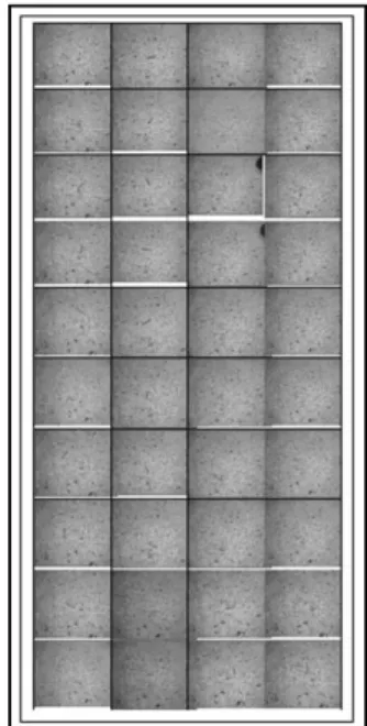
The study was carried out by using 60 real data sets extracted form landmark images. Data for the study were obtained from vision system of Web-SUNAR shown in Fig. 4. Some of the raw image data used for training of ANN after preprocessing is shown in Fig.8.
Figure 8. Some of the training sets
Prior to training, all variables were normalized between 0 and 1. The data used to train and test the back propagation neural network model are subdivided into two sets: a first set of 48 observations, to train the neural network model and a second set of 12 observations to test the model. The structure of the network (number of layers, number of hidden nodes, learning rate, momentum values) is optimized during the training phase, to guarantee good learning and recognition of landmarks.
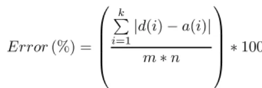
After training and test phase, the error calculation given in Equation 13 was used as performance criterion in determining both number of hidden layer nodes and optimum momentum and learning coefficients [17].
(13) (%) = ⎛ ⎜ ⎜ ⎜ ⎝ P =1|() − ()| ∗ ⎞ ⎟ ⎟ ⎟ ⎠∗ 100
where d() is desired outputs, () is outputs of neural network, is the number of samples in training or test data, is the number of segments in training or test data and is the number of outputs of neural network [13].
In addition, the test results satisfying the minimum errors were subjected to R-Square correlation test given in Equation 15. These correlation values were used as another criterion for the determination of optimum ANN structure.
(14) = P ( − ¯) ( − ¯) qP ( − ¯)2P( − ¯)2 4. Experimental Results
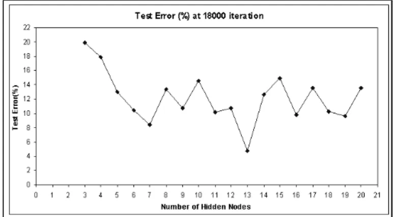
Seven features are extracted for red pair of landmark image by using invariant moment equations given in Eqs.1-11. These values are used to be input for neural network recognition units. In this study, feed-forward multi layer per-ceptron artificial neural network structure was used for landmark recognizing. The neural network was trained with back propagation training algorithm. There are 7 input nodes on input layer. For the optimum ANN structure, number of hidden nodes in the hidden layer was found as 13 experimentally. Minimum training and test errors were obtained for this number of hidden nodes.
Figure 10. Plot of test error versus number of hidden nodes
Figure 11. Plot of output of ANN versus desired output (R-square value)
In the training, the number of iterations was set to 18000 and learning rate of the network was set to = 09. The momentum coefficient adjusting learning speed was set to = 07. ANN structure was trained with 48 sets of data and then tested under the best optimum structure determined by trials. During the testing process of the system, 12 sets of data were used. Training and test errors of the system were 2.61% and 4.73%, respectively. Correlation analysis of columns was performed and the results of these analyses were calculated as r2=0.85.
5. Conclusions
In this study, a landmark detection system has been successfully developed by using image processing techniques and ANN for a web based mobile robot (SUNAR). The landmark detection system has been realized with online pro-gramming through internet on SUNAR and the system has been designed to operate in real-time.
In literature, a lot of landmark detection methods have been proposed. However, only a small part of these methods are suitable for web-robots and real-time operations. Also, the methods suitable for a web-robot and real-time operation usually do not completely matches with other robots. Therefore, our landmark detection system completely matches SUNAR as it was distinctly designed to meet the requirements of it.
In this context, speed of detection process is a vital concern. Speed of realized detection system is sufficient for SUNAR (about 140 ms). Another impor-tant feature of SUNAR is capability of internet-based full programmability via web-interface. Programming on web-interface can be implemented only with commands produced for SUNAR. Therefore, program of the detection system can be easily changed from anywhere through internet. (Also, research groups worldwide can be organized for finding best landmark detection methods)(Bu cümle buraya pek uymu¸s görünmedi ama ben anlayamam¸s da olabilirim). Or the landmark detection system can be adapted to an experiment in robot vision lessons for graduate students.
Feature extraction system in SUNAR has a powerful operating capability. How-ever, only invariant moments are used as feature. Even in this condition, system test error is suitable for SUNAR.
In this system, a neural network program named as NeroNY was used for ANN activities. Furthermore, all of the results were checked with the ones obtained from Neural Network Toolbox of MATLAB. The trained network is uploaded to SUNAR as a file with web-interface.
Even though the work presented here is in its early stages, it still shows that it is feasible to carry out landmarking with other feature extraction methods. The authors will focus on these applications in further studies.
References
1. H. Asoh, Y.Motomura, F. Asano, I. Hara, S. Hayamizu, K. Itou, T. Kurita, T. Matsui, N. Vlassis, R. Bunschoten, B. Krose: Jijo-2 (2001): An Office Robot that Communicates and Learns, Intelligent Systems, IEEE, Vol.16, 46-55.
2. N. Diolaiti, C. Melchiorri (2002): Teleoperation of a Mobile Robot Through Haptic Feedback Haptic Virtual Environments and Their Applications, IEEE International Workshop HAVE (17-18 Nov. 2002) 67 -72.
3. K.J. Schilling, H. Roth (1999): Control Interfaces for Teleoperated Mobile Robots, Emerging Technologies and Factory Automation, Proceedings. ETFA ’99. 1999 7th IEEE International Conference on, Vol.2, Barcelona Spain, 1399 -1403.
4. J.B. Park , B.H. Lee, M.S. Kim (2003): Remote Control of a Mobile Robot Us-ing Distance-Based Force, ProceedUs-ings of the 2003 IEEE International Conference on Robotics & Automation, Vol.3, Taipei, Taiwan, 3415-3418.
5. K.J. Schilling, M.P. Vernet (2002): Remotely Controlled Experiments with Mobile Robots, System Theory, 2002. Proceedings of the Thirty-Fourth Southeastern Sympo-sium, 71-74.
6. K. Matsumaru , A. Fhjimori , T. Kotoku , K. Komoriya (2000): Action Strategy for Remote Operation of Mobile Robot in Human Coexistence Environment, Industrial Electronics Society, 2000 IECON 2000. 26th Annual Conference of the IEEE, Vol.1, Nagoya Japan, 1-6.
7. T.-H.S. Li, S.-J. Chang , Y.-X. Chen (2003): Implementation of Human-Like Driving Skills by Autonomous Fuzzy Behaviour Control on An FPGA-Based Car-Like Mobile Robot, IEEE Transactions on Industrial Electronics, Vol.50,867-880.
8. S. Vitabile, G. Pilato, F. Pullara , F. Sorbello (1999): A Navigation System for Vision-Guided Mobile Robots, Image Analysis and Processing, 1999. Proceedings. International Conference, Venice Italy, 566 -571.
9. R.C. Luo, T.M. Chen (2000) : Development of a Multibehaviour-based Mobile Robot for Remote Supervisory Control through the Internet, IEEE/ASME Transaction on Mechatronics, Vol.5, 376-385.
10. K.-J. Yoon, I.-S. Kweon (2001): Artificial Landmark Tracking Based on the Color Histogram, International Conference on Intelligent Robot and Systems, Proceedings of the 2001 IEEE/RSJ, Msui Hawaii USA, 1918-1923
11. M. Hebert (1992) : 3-D Landmark Recognition from Range Images, IEEE Com-puter Society Conference on ComCom-puter Vision and Pattern Recognition, (15-18 Jun 1992) 360-365.
12. N. Yılmaz (2005): Design, Realization And Applications Of A Web-Based Mo-bile Robot System, PhD Thesis, Selcuk University, Institute of Natural and Applied Sciences, Konya, TURKIYE (in Turkish).
13. N. Yılmaz, ¸S. Sa˘gıro˘glu, M. Bayrak (2005): A Web Based Semi-Autonomous Mobile Robot: SUNAR, TAINN2005, Cesme, Izmir, 410-417.
14. ¸S. Sa˘gıro˘glu, N. Yılmaz, M. Bayrak (2005): Design and Implementation of A Web Based Mobile Robot, Virtual International Conference on Intelligent Production Machines and Systems, Wales, UK, July 4-15.
15. B. Karlık, M.O. Tokhi, M. Alci (2003): A Fuzzy clustering neural network ar-chitecture for multifunction upper-limb prosthesis, IEEE Trans. on Biomedical Eng. Vol.50, No.11, November.
16. S. Haykin (1994): Neural Networks: A Comprehensive foundation, New York, Macmillan.
17. Y. Ozbay, R. Ceylan, B. Karlık (2005): A Fuzzy clustering neural network ar-chitecture for classification of ECG arrhythmias, Computers in Biology and Medicine, (Article in press).