Connectivity Analysis of an AUV Network
with OFDM Based Communications
Alper Bereketli
1, Muharrem T¨umc¸akır
1, ˙Ilkay Yazgı
1, Burcu Yeni
1,
Mehmet Koseoglu
2and Tolga M. Duman
31Defense Systems Technologies Division, ASELSAN Inc., Ankara, Turkey
E-mail: {abereketli,mtumcakir,iyazgi,byeni}@aselsan.com.tr
2Department of Computer Engineering, Hacettepe University, Ankara, Turkey
E-mail: [email protected]
3Department of Electrical and Electronics Engineering, Bilkent University, Ankara, Turkey
E-mail: [email protected]
Abstract—Autonomous underwater vehicle (AUV) networks play a crucial role in tactical, commercial, and scientific appli-cations, where reliable and robust communication protocols are needed due to the challenging characteristics of the channel. With this motivation, connectivity of AUV networks in different regions with varying transducer characteristics are analyzed through simulations based on real-life orthogonal frequency division multiplexing (OFDM) based communication experiments over noisy and Doppler-distorted channels. Doppler compensation is performed according to the autocorrelation using the cyclic prefix. Using binary and quadrature phase shift keying (BPSK and QPSK) modulation schemes in conjunction with low density parity check (LDPC) coding, error rate levels are investigated through shallow water pond and at-sea experiments. It is shown that, the utilized transmission scheme is capable of correcting all bit errors among nearly one million bits transmitted up to a distance of 1 km, yielding a payload rate of 15.6 kbps with 4096 subcarriers and QPSK modulation. The simulations provide key parameters that must be taken into account in the design of scalable and connected AUV networks.
Keywords—Autonomous Underwater Vehicle, AUV Network, Underwater Acoustics, OFDM Communication, Connectivity.
1. INTRODUCTION
Underwater communications and data retrieval are required for applications such as tactical surveillance, navigation, track-ing, naval operations, oceanography, marine biology, and com-mercial research [1], [2]. Since the absorption of acoustic waves is about three orders of magnitude lower than elec-tromagnetic waves for most of the communication frequency spectrum, underwater networks can be based on wireless acoustic communications [3]. However, reliable and robust network protocols are required due to the challenging char-acteristics of underwater acoustic channel including extended multipath, rapid time variations, large propagation delays, and limited available bandwidth [4]-[6].
With the development of advanced processing capabilities and power supplies, autonomous underwater vehicles (AUVs) are now being used for tasks with evolving roles and missions such as intelligence, surveillance, reconnaissance, military countermeasures, anti-submarine warfare, oceanography, and remote communication [7]. Most of the AUV studies in the literature focus on navigation, guidance, path determination,
or point-to-point (P2P) communications [7]-[11]. To establish an AUV network with certain mobility characteristics, reliable and adaptive networking protocols must be developed. More-over, resolving connectivity losses among AUVs remains a crucial topic under dynamic conditions where AUVs join or leave the network due to mission path changes and energy depletion.
In this work, connectivity of AUV networks with varying transducer characteristics are analyzed in different operation regions through simulations based on the results of real-life orthogonal frequency division multiplexing (OFDM) based communication experiments. In the experiments, binary and quadrature phase shift keying (BPSK and QPSK) modulation schemes are utilized in conjunction with low density parity check (LDPC) coding. Bit error rate levels are investigated through shallow water pond and at-sea experiments. It is shown that, the algorithm is capable of correcting all bit errors among nearly one million bits up to a transmission range of 1 km, yielding a payload rate of 15.6 kbps with 4096 subcarriers and QPSK modulation. The simulations provide insights on the relationship of the number of nodes, transmission range, size of the operational region and network connectivity.
The rest of the paper is organized as follows. Details of the shallow water and pond and at-sea experiments are presented together with the bit error rate and range results in Section 2. Section 3 includes a detailed discussion on the connectivity of AUV networks based on the P2P performance results obtained. Section 4 concludes the paper with further comments and a summary of future work.
2. POINT-TO-POINTCOMMUNICATIONEXPERIMENTS
Under frequency-selective distortion, multicarrier modula-tion may be preferable instead of single carrier modulamodula-tion to remove the inter-symbol interference. Furthermore, OFDM scheme is implemented efficiently using low-complexity re-ceiver architectures, since it provides a simple means of channel equalization in the frequency domain [12]-[15]. Con-sequently, it may be advantageous to use OFDM to overcome interference and fading issues of mobile ad hoc AUV net-works. Therefore, as the first step of developing an AUV
DATA FRAME
Codeword 1 Codeword 2 Codeword 3 Codeword 4
1 2 3 4 5 6 7 8 9 10 11 12 13 14 15 16 1 2 3 4 5 6 7 8 1 2 3 4 5 6 7 8 1 2 3 4 BPSK 2048 BPSK 4096 QPSK 2048 QPSK 4096
OFDM Word Index
Fig. 1. Codeword and OFDM word structure of a data frame for different modulation schemes.
network, OFDM based P2P communications are tested over noisy and Doppler-distorted channels for shallow water and pond and at-sea experiments.
OFDM is sensitive to frequency offset and Doppler effects due to the relative motion of transmitter and receiver as well as other time variations in the medium. To solve this problem, we extract Doppler scaling effects using the correlation of the cyclic prefix and its replica at the tail of OFDM symbols. For time synchronization, a linear frequency-modulated waveform (chirp) of duration 100 ms is used as a preamble at each frame before data symbols. The receiver correlates its received samples with a local replica of the chirp to estimate the beginning of the transmission. The chirp waveform is followed by a silence period of 100 ms. Then, ten OFDM words, each of which is preceded by a cyclic prefix of length 48 ms, are transmitted consecutively.
The OFDM based communication system is tested with BPSK and QPSK schemes, where the number of subcarriers is either k = 2048 or k = 4096 in the frequency band 10-30 kHz. Each OFDM word contains 1024 data bits for BPSK with 2048 subcarriers, 2048 bits for BPSK with 4096 subcarriers and QPSK with 2048 subcarriers, and 4096 bits for QPSK with 4096 subcarriers. The remaining 50% of the symbols are used as pilot symbols to estimate the channel characteristics. The length of the cyclic prefix is 48 ms. Total transmission durations for the OFDM words are 154 ms and 261 ms for k = 2048 and k = 4096 subcarriers, respectively. The sampling frequency used in the system is 192 kHz, and a data frame is composed of four OFDM codewords, each having a length of 4096 bits. Consequently, our payload rate varies between 6.6 kbps (BPSK with k = 2048) and 15.6 kbps (QPSK with k = 4096).
LDPC coding [16] is used to correct bit errors to enhance data transmission over noisy channels. In order to improve the bit error rate (BER) performance, pilot-based channel estimation and Doppler compensation are coupled with a 1/5-rate (4096,820) LDPC code. The results of tests at various ranges are used to investigate the BER performance which are then used to analyze the AUV network deployment and the connectivity in MATLAB.
A controlled experimental setup is prepared at the open water test and calibration facility of ASELSAN at METU Yalıncak Pond, shown in Fig. 2. The pond allows for ex-periments up to a range of 150 m, and it has an average depth of 10 m, which provides a challenging shallow water
Fig. 2. Test and calibration facility of ASELSAN at METU Yalıncak Pond.
test environment.
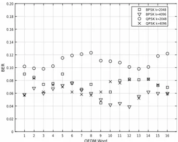
The transmitter and the receiver are submerged to a depth of 3 m, with the transmitter drifting away at 2 knots. The mobile source transmits with an approximate acoustic source level of 160 dB re µPa. Fig. 3 shows the BER levels prior to error correction for 16 consecutive OFDM words transmitted from a distance of 150 m using BPSK and QPSK. The BER levels achieved at the pond experiments do not exceed 0.13 and they are within correctable limits of the LDPC code, enabling the correction of all errors among a million bits (60 frames) at these ranges.
During the at-sea experiments, measurements are collected in a shallow water medium with a maximum depth of 80 m. The receiver is stationary at a depth of 15 m, where the depth of water column is around 30 m. The transmitter is mobile at approximately 5 knots. It is submerged to a depth of 15 m, and it is drifting in the offshore direction up to a distance of 1 km, where the water depth increases gradually to 80 m.
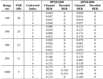
Table 1 shows the initial BER results from the demodulation of the received signal for BPSK with 2048 subcarriers and
OFDM Word 1 2 3 4 5 6 7 8 9 10 11 12 13 14 15 16 BER 0 0.02 0.04 0.06 0.08 0.10 0.12 0.14 0.16 0.18 0.20 BPSK k=2048 BPSK k=4096 QPSK k=2048 QPSK k=4096
TABLE 1
BER LEVELS FORBPSK 2048ANDQPSK 4096 MODULATIONSCHEMES
BPSK2048 QPSK4096
Range SNR Codeword Channel Decoded Channel Decoded
(m) (dB) Index BER BER BER BER
100 30 1 0.045 0 0.029 0 2 0.047 0 0.014 0 3 0.043 0 0.010 0 4 0.040 0 0.057 0 300 25 1 0.006 0 0.133 0 2 0.010 0 0.121 0 3 0.008 0 0.131 0 4 0.015 0 0.178 0 500 22 1 0.028 0 0.079 0 2 0.026 0 0.062 0 3 0.031 0 0.075 0 4 0.043 0 0.079 0 850 11 1 0.132 0 0.113 0 2 0.166 0 0.176 0 3 0.130 0 0.095 0 4 0.151 0 0.130 0 1000 5 1 0.175 0 0.178 0 2 0.238 0.330 0.177 0 3 0.242 0.334 0.180 0 4 0.174 0 0.169 0
QPSK with 4096 subcarriers. The table shows the BER results and signal-to-noise ratio (SNR) for frames received at different ranges between 100-1000 m. At short ranges between 100-300 m, most of the BER levels remain under 0.13 and all bit errors among about 1 million bits are corrected at high SNRs, which is in compliance with the previous pond experiments shown in Fig. 3. As a result of instantaneous changes in the noise level and sea conditions, modulation types show varying BER behavior for some consecutive OFDM words. Still, the channel BER is generally below 0.20, and all bit errors among the 50 frames (819200 data bits) transmitted are corrected with the help of the LDPC code up to a range of 850 m. Beyond that range, SNR goes below 10 dB at 1000 m, starting to yield BER levels above 0.20. Therefore, using the acoustic source level of 160 dB re µPa, the maximum practically achievable transmission range for our system is 1000 m for most of the codewords according to the BER performance obtained from the sea experiments.
3. CONNECTIVITY OF ANADHOCAUV NETWORK
Using experimental P2P communication data collected at our tests, we now analyze the connectivity of an AUV network through simulations with respect to the network size, transmission range, and number of nodes. In an AUV network, data must be reliably communicated via sensor nodes. Depending on the type of application, deterministic broadcast, probabilistic broadcast, or multicast mechanisms can be utilized in an AUV network [17]. Therefore, in order to guarantee communication connectivity, it is important to carefully investigate the number of required nodes according to the deployment region and the sensor characteristics such as the transmission range, which is discussed in Section 2. We study the connectivity properties of an ad hoc AUV network where a number of battery-powered AUVs are sent by a central underwater vehicle (e.g., a submarine) for a predefined mission such as surveillance or protection. Here we are interested in
Range (m) -1000 -500 0 500 1000 Range (m) -1000 500 0 500 1000
Fig. 4. The 2D directional transmission range of the transducer versus the omnidirectional range that we use as a benchmark (Top view). The arrow indicates the direction of the transducer.
determining the percentage of “connected” nodes which can receive a broadcast message either directly from the central vehicle or via a relay node. This ratio is crucial as the disconnected nodes will not receive orders from the base; hence, will be unable to continue their missions.
We investigate the effects of several parameters on the connectivity using a simulation software written in MATLAB. First, we consider the effect of the transmission pattern of the transducers in our AUVs. In most of the studies in the literature, the transducers are assumed to be omnidirectional. This assumption is not valid in practice; because, if the transducers are mounted in front of the AUV, it severely limits transmission towards the back of the vehicle. For example, the transmission pattern of our directional transducers shown in Fig. 4 is obtained at 20 kHz along with the omnidirectional pattern that we use as a benchmark based on the range results presented in the previous section. This beam pattern is constructed by scaling the range in the omnidirectional case by the angular transmitting voltage response (TVR) of our transducer. It can be seen that the transmission range towards the back of the vehicle is approximately half of the maximum transmission range.
We performed several simulations to investigate the effect of the directional transmission pattern on the connectivity. We consider N uniformly distributed AUVs over a circular area with radius R. The source node is at the center of the circular region. We first mark the nodes in the transmission range of the data source as connected. Among the remaining nodes, we then find the ones reachable through relaying of newly connected nodes. We continue this process until no new nodes are marked as connected.
Fig. 5 shows the percentage of disconnected nodes for both an omnidirectional antenna and the directive antenna for
10 20 30 40 50 60 70 80 90 100 Node Count 0 0.1 0.2 0.3 0.4 0.5 0.6 0.7
Ratio of Disconnected Nodes
Directional Transmission Omnidirectional Transmission
Fig. 5. Percentage of disconnected nodes as the number of nodes increases for both an omnidirectional antenna and a directional antenna in the AUVs.
R = 2.5 km. The orientation of the nodes are assumed to be random. It can be seen that approximately twice as many nodes are needed to achieve the same connectivity with a directional antenna in comparison to an omnidirectional antenna. This result suggests that the transmission pattern of the antenna is crucial in designing an AUV network.
From these figures, it can be seen that the number of nodes needed to have a well connected network is very high. For example, to have a network with less than 10% disconnected nodes over a circular area with 2.5 km radius requires approximately 50 AUVs. Some missions, however, may not require the network to cover an entire circular region around the central vehicle. For example, in protection missions against an approaching danger, nodes need only to operate in a limited area. With this motivation, we have also investigated the change in the connectivity in the network when the nodes are distributed over a circular section instead of the full disc. Fig. 6 shows the change in the connectivity when 20 nodes are confined in a circular section with angle α and radius R. When α = 360, it is equivalent to the full disc case. It can be seen that the ratio of disconnected nodes significantly reduces as the angle of the circular section reduces. For example, for R = 3 and α = 360, 75% of the nodes are disconnected on the average but for α = 90, it is 24% due to the reduction in the area.
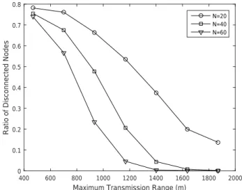
We have also simulated how the connectivity changes as the maximum transmission range changes. We assume that the transmission is still directional, as shown in Fig. 4, however we scale the transmission pattern to investigate the effect of varying range. Fig. 7 shows the ratio of connected nodes as a function of the maximum transmission range. As the range increases, the connectivity of the network improves. It is possible to obtain a significant reduction in the numbers of AUVs by an increase in the transmission range. For example, when the maximum transmission range improves from 1200 m to 1400 m, the number of AUVs needed to have approximately
50 100 150 200 250 300 350
Angle of the Circular Section
0 0.1 0.2 0.3 0.4 0.5 0.6 0.7 0.8 0.9
Ratio of Disconnected Nodes
R = 2 km R = 3 km R = 4 km
Fig. 6. Percentage of disconnected nodes as the radius and the angle of the circular section changes for 20 AUVs.
5% disconnected nodes reduces from 40 to 20. 4. CONCLUSION
We have recently been working on the development of AUV networks built on a robust physical layer. P2P communication based on OFDM is tested over noisy and Doppler-distorted channels in shallow water pond and at-sea experiments. Un-coded error rates and error correction performance of LDPC coding are investigated. BER performances of BPSK and QPSK modulation schemes are studied. It is shown that bit errors among nearly one million bits (50 data frames) are corrected up to a range of 1 km, yielding a payload rate of 15.6 kbps using QPSK with k = 4096. Using the BER and transmission range results, AUV network connectivity is also analyzed in different geometries with varying transducer transmission characteristics through simulations. The results
400 600 800 1000 1200 1400 1600 1800 2000
Maximum Transmission Range (m)
0 0.1 0.2 0.3 0.4 0.5 0.6 0.7 0.8
Ratio of Disconnected Nodes
N=20 N=40 N=60
Fig. 7. Ratio of disconnected nodes as the maximum transmission range changes.
provide key parameters that must be taken into account in the design of scalable and connected AUV networks. Upon the realization of P2P communication, unique protocols will be developed for medium access, network, and transport layers of a protocol stack. This expertise will be used in the design and implementation of a novel digital underwater acoustic modem that is capable of supporting networking protocol algorithms, as well as JANUS [18], which is in the process to become a NATO standard intended for international adoption. In addition, realization of such a modem will enable AUVs and submarines to convey status or Identification Friend or Foe (IFF) information to their headquarters.
REFERENCES
[1] I. F. Akyildiz, D. Pompili, and T. Melodia, “Underwater acoustic sensor networks: research challenges,” Ad Hoc Networks, vol. 3, no. 3, pp. 257-279, May 2005.
[2] M. Chitre, S. Shahabudeen, and M. Stojanovic, “Underwater acoustic communications and networking: Recent advances and future challenges,” Marine Technology Society Journal, vol. 42, no. 1, pp. 103-116, Spring 2008.
[3] A. D. Waite, “Sonar for Practising Engineers,” Wiley, 2002.
[4] J. Heidemann, M. Stojanovic, and M. Zorzi, “Underwater sensor networks: applications, advances and challenges,” Philosophical Trans-actions of the Royal Society A: Mathematical, Physical and Engineering Sciences, vol. 370, no. 1958, pp. 158-175, Jan. 2012.
[5] E. Sozer, M. Stojanovic, and J. Proakis, “Underwater Acoustic Networks,” IEEE Journal of Oceanic Engineering, vol. 25, no. 1, pp. 72-83, Jan. 2000.
[6] J. Partan, J. Kurose, and B. N. Levine, “A Survey of Practical Issues in Underwater Networks,” ACM SIGMOBILE Mobile Computing and Communications Review, vol. 11, no. 4, pp. 23-33, Oct. 2007. [7] J. Yuh, “Design and control of autonomous underwater robots: A survey,”
Autonomous Robots, vol. 8, no. 1, pp. 7-24, 2000.
[8] L. Freitag, et al., “A shallow water acoustic network for mine countermea-sures operations with autonomous underwater vehicles,” in Underwater Defense Technology (UDT), 2005.
[9] D. R. Yoerger, et al., “Techniques for deep sea near bottom survey using an autonomous underwater vehicle,” The International Journal of Robotics Research, vol. 26, no. 1, pp. 41-54, 2007.
[10] H. Jia, et al., “Three-dimensional path tracking control for autonomous underwater vehicle based on neural network,” Control Theory and Applications, vol. 29, no. 7, pp. 877-883, 2012.
[11] D. Li, et al., “Autonomous underwater vehicle docking system for cabled ocean observatory network,” Elsevier Ocean Engineering, vol. 109, pp. 127-134, 2015.
[12] Y. Emre, et al., “Multi-Input Multi-Output OFDM for Shallow-Water UWA Communications,” in Proc. Acoustics 08, pp. 5333-5338, Paris, 2008.
[13] K. Tu, et al., “Cooperative MIMO-OFDM Communications: Receiver Design for Doppler Distorted Underwater Acoustic Channels,” in Proc. Asilomar Conference on Signals, Systems and Computers, pp. 1335-1339, Pacific Grove, CA, November 2010.
[14] K. Tu, et al., “Multiple-Resampling Receiver Design for OFDM over Doppler-Distorted Underwater Acoustic Channels,” IEEE Journal of Oceanic Engineering, vol. 38, no. 2, pp. 333-346, April 2013. [15] B. Li, et al., “Multicarrier communication over underwater acoustic
channels with nonuniform Doppler shifts,” IEEE Journal of Oceanic Engineering, vol. 33, no. 2, pp. 198-209, 2008.
[16] W. Ryan and S. Lin, “Channel Codes: Classical and Modern,” Cam-bridge University Press, 2009.
[17] M. Koseoglu, A. Bereketli, I. Yazgi, and B. Yeni, “Probabilistic broadcast for dense AUV networks,” in Proc. MTS/IEEE OCEANS’16, pp. 1-5, Monterey, CA, Sep. 2016.
[18] J. Potter, et al., “The JANUS underwater communications standard,” in Underwater Communications and Networking (UComms), pp. 1-4, Sestri Levante, 2014.