which both fabricated of compact size only 28⫻ 26.4 mm2. To obtain the wider band, the notch on the ground plane and the T-type radiatoin patch have been optimal by parameter analysis. Furthermore, embedded a narrow invert-L slit on T-type monopole to yield band-notch characteristics. The broadband operation from 1.95 to 6.55GHz, and the triple-band operation from 1.69 to 2.72 GHz, 3.26 to 4.07 GHz, and 5.01 to 6.24 GHz. The proposed antenna could be attractived for WLAN/WiMAX applications. REFERENCES
1. Deploying License-Exempt WiMAX Solutions, Available at: http:// www.intel.com/netcomms/technologies/wimax/.
2. W.S. Chen, Y.C. Chang, and F.S. Chang, Novel design of printed monopole antenna for WiMAX application, Microwave Opt Technol Lett 49 (2007), 1806 –1809.
3. W.S. Chen and B.H. Kao, The design of printed rectangular slot antenna with a small isosceles triangle slot for WiMAX applications, Micro-wave Opt Technol Lett 48 (2006), 1821–1824.
4. S.W. Su and K.L. Wong, Wideband antenna integrated in a system in package for WLAN/WiMAX operation in a mobile device, Microwave Opt Technol Lett 48 (2006), 2048 –2053.
5. P.L. Carro and J.D. Mingo, Polarization diversity with genetic parrallel printed dipole antennas for bluetooth and wimax applications, 64th IEEE Vehicular Technology Conference, 2006, pp. 1–5.
6. Y.S. Shin and S.O. Park, A compact loop type antenna for Bluetooth, S-DMB,wibro,wimax and wlan applications, IEEE Antennas Wireless Propag Lett, accepted for future publication.
7. F.R. Hsiao and K.L. Wong, Omnidirectional planar dipole antenna, IEEE Trans Antennas Propagat 52 (2004), 1898 –1902.
8. Y. Rikuta and R. Kohno, Planar monopolo antenna with dual frequency for UWB system, IEEE UWB Syst Technol Conf (2003), 176 –179. © 2007 Wiley Periodicals, Inc.
A COMPARATIVE INVESTIGATION OF
SRR- AND CSRR-BASED
BAND-REJECT FILTERS: SIMULATIONS,
EXPERIMENTS, AND DISCUSSIONS
V. O¨ znazı1,2and V. B. Ertu¨rk11Department of Electrical and Electronics Engineering Bilkent
University, TR-06800 Bilkent, Ankara, Turkey; Corresponding author: [email protected]
2Aselsan Electronics Inc., Ankara, Turkey
Received 4 July 2007
ABSTRACT: A comparative investigation of split-ring resonator
(SRR)-and complementary split-ring resonator (CSRR)-based b(SRR)-and-reject filters is performed. These compact band-reject filters are obtained by loading simple 50-⍀ microstrip lines with SRRs and CSRRs that have exactly the same shape and dimensions. Unlike the previous studies, stopband charac-teristics of these filters, such as resonance frequency, band-width, sharp-ness, and amount of attenuation in the rejection region based on the num-ber of SRR or CSRR stages, are investigated in a detailed and comparative manner. Based on simulations that are accompanied by experimental re-sults, it has been observed that some of the aforementioned stopband char-acteristics of SRR-based band-reject filters are significantly different than those of CSRR-based band-reject filters. This makes SRR- or CSRR-based filters preferable depending on applications. © 2007 Wiley Periodicals, Inc.
Microwave Opt Technol Lett 50: 519 –523, 2008; Published online in Wiley InterScience (www.interscience.wiley.com). DOI 10.1002/mop. 23119
Key words: split-ring resonator (SRR); complementary split-ring
reso-nator (CSRR); band-reject filters; single-negative (SNG) medium
1. INTRODUCTION
Recently, split-ring resonators (SRRs) [1] and complementary split-ring resonators (CSRRs) [2] have been used in planar circuit technology for the design of novel printed microwave components, in particular, bandpass and band-reject filters [2–21]. It has been shown that when loaded with SRRs, both microstrip lines [8 –11, 20, 21] and coplanar waveguides [3, 4, 12] behave as compact, high-Q, band-reject filters with deep stopbands in the vicinity of their resonant frequencies. A simple way of explaining this phenomenon is that the presence of SRRs in close proximity to the signal transmission line (microstrip or coplanar waveguide) generates an effective single-negative (SNG) medium with negative effective permeability, eff, around their resonant frequencies, and previously propagating waves (in the absence of SRRs) become evanescent waves. As a result, the signal propagation is inhibited. Moreover, by performing small modifications (addition of shunt metallic strips, possibly vias or series capacitive gaps) on the aforemen-tioned structures, novel bandpass filters are introduced in Refs. 5–7, some of which are left-handed due to the generation of a double-negative medium (coexistence of negative effective per-mittivity, eff, and negative permeability, eff), which facili-tates signal propagation with negative phase velocity in the passband. In a similar fashion, when loaded with CSRRs, microstrip lines also behave as high-Q band-reject filters with deep stopbands around their resonant frequencies [2, 15]. Since CSRRs are dual counterparts of SRRs, etching CSRRs in the ground plane just beneath a microstrip line (simplest and most standard configuration) yields an effective SNG medium with negativeeff. Thus, because the previously propagating waves (in the absence of etched CSRRs) become evanescent waves, the signal propagation is again inhibited. Finally, as in the case of SRRs, these structures can be converted to bandpass filters with small modifications [13–14, 16 –19, 21].
In this paper, we perform a comparative investigation of SRR- and CSRR-based band-reject filters by examining their stopband characteristics in a detailed manner, which constitutes the main contribution of this paper. Two very simple band-reject filter topologies, one for SRR and the other for CSRR, with exactly the same SRR and CSRR dimensions are chosen so that simulation and fabrication based errors can be minimized and a fair comparison of their stopband characteristics can be performed. It has been observed that with both topologies significant attenuation levels can be obtained using a few SRR or CSRR stages in the vicinity of a microstrip line. Therefore, both topologies offer very compact band-reject filters as men-tioned in the aforemenmen-tioned studies. However, some important stopband characteristics of SRR-based band-reject filters sig-nificantly differ from their CSRR-based counterparts, which have not been reported previously. Bandwidth, sharpness of the transition from passband region to stopband region (and vice versa) and effects of number of SRR and CSRR stages on the amount of attenuation in the stopband region are among these characteristics.
In Section 2, SRR and CSRR based band-reject filter designs are given together with simulations supported by measurement results. Section 3 provides a detailed discussion of the stopband characteristics of the designed SRR- and CSRR-based band-reject filters in terms of the operation (resonance) frequency, bandwidth, sharpness of the transition from passband to stopband and vice versa, amount of rejection level in the stopband, and how this level varies with the number of SRR and CSRR stages.
2. SRR- AND CSRR-BASED BAND-REJECT FILTERS
2.1. SRR-Based Band-Reject Filter
Having a strongly anisotropic electromagnetic nature, the SRR is able to inhibit signal propagation in a narrow band in the vicinity of its resonant frequency, provided that it is illuminated by a time-varying magnetic field with an appreciable component in its axial direction. A microstrip transmission line that allows propa-gation of quasi-TEM modes induces magnetic field lines that close upon themselves around the line. If two arrays of SRRs exist closely at both sides of the host microstrip line, a significant portion of the magnetic fields induced by the line is expected to cross the SRRs with the desired polarization. These arrays of SRRs, under the illumination of the time-varying magnetic field with the desired polarization, constitute an effective SNG medium with negative eff. Thus, previously propagating waves in the absence of SRRs become evanescent waves. Consequently, the signal propagation is inhibited.
Based on this explanation, an SRR-based band-reject micro-strip filter has been designed and fabricated as shown in Figure 1. In this initial design, six SRR pairs (i.e., a total of 12 SRRs forming six stages) have been employed. The topology and the relevant dimensions of these SRRs are also given in the inset and captions of Figure 1, respectively. The width of the central strip is set to 1.15 mm, so that its characteristic impedance is⬃50 ⍀ and low out-of-band return loss levels are suffered at both port sides. To enhance the coupling of the SRR structures to the central line, square-shaped SRRs rather than originally proposed circular ones have been used. In the fabrication process, a mechanical etching technique has been employed. The filter has been implemented on a RO4003C high-frequency laminate, which is commercially available from Rogers Corporation, with the following material properties: relative dielectric constantr⫽ 3.38, substrate height 20 mm (i.e., 0.508 mm), and the thickness of the copper cladding is 1 oz (i.e., 35 m). The coupling could have been further improved by minimizing the distance between the line and the rings. However, mechanical etching techniques available at hand lose their accuracies for separations less than about one-fifth of a millimeter and cause significant discrepancies between the mea-sured and simulated results. Therefore, the distance between the
rings and the line is set to 0.3 mm. After soldering 3.5-mm SMA female connectors at both ports, scattering parameters have been measured using an Agilent PNA series N5230A vector network analyzer. Numerical calculations of the scattering parameters have been performed using the method of moments -based electromag-netic solver of Ansoft Designer commercial software [22]. Mea-sured and simulated insertion and return losses are presented in Figure 2. Good agreement is achieved between the numerical and experimental results, especially in terms of the center frequency of the stopband, which is 9.25 GHz. Some minor discrepancies be-tween the measured and simulated return loss values can be attributed to possible impedance mismatches as a result of coax-to-microstrip transitions at both connector sides and also imper-fections in the fabrication process.
2.2. CSRR-Based Band-Reject Filter
Being the dual counterpart of the conventional SRR, the CSRR requires the excitation of a time-varying electric field having a strong component parallel to its axis so that it can resonate at some frequencies. A microstrip transmission line induces electric field lines that originate from the central strip and terminate perpendic-ularly on the ground plane. Owing to the presence of the dielectric substrate, field lines are tightly concentrated just below the central conductor, and the electric flux density reaches its maximum value in the vicinity of this region. Hence, if an array of CSRRs is etched on the ground plane just aligned with the microstrip line, a strong electric coupling with the desired polarization is expected. As a result, a linear array of CSRRs constitutes an SNG medium with a negativeeff. Therefore, similar to the SRR-based case, previously propagating waves in the absence of CSRRs become evanescent waves. Consequently, the signal propagation is again inhibited.
Considering the aforementioned physical picture, a CSRR-based band-reject filter has been designed and fabricated as illus-trated in Figure 3. All dimensions of the CSRRs have been selected identical to their counterparts in SRR-based case (dimensions are given in the caption of Fig. 3), so that the operating frequency of the current filter is around 9.25 GHz, too. Again six CSRR stages Figure 1 Fabricated SRR-based microstrip band-reject filter; relevant
dimensions: W⫽ 3 mm, c ⫽ d ⫽ g ⫽ 0.3 mm. [Color figure can be viewed in the online issue, which is available at www.interscience.wiley.com]
Figure 2 Measured and simulated scattering parameters of the SRR-based band-reject filter
(CSRRs do not appear in pairs) have been employed. During the fabrication process, the filter has been implemented on the same high-frequency laminate. By this way, a comparative analysis between the two filter types can be performed. Notice that, because the distance between the microstrip line and the CSRRs is deter-mined by the thickness of the laminate, this configuration does not allow us to adjust the distance between the CSRRs and the line easily, unless a laminate with different substrate height is used. Optionally, using a dielectric substrate with a higher permittivity can more effectively confine the electric field lines into the dielec-tric slab rather than extending into the air, and a stronger capacitive coupling due to the increased permittivity can be obtained result-ing in an enhanced suppression level. Shape of the CSRRs is not expected to have a drastic effect on the amount of coupling, but we have preferred to make use of square CSRRs to be consistent with the topology in the SRR-based case. Therefore, the comparative analysis of the two cases carried out here is expected to depend only on whether the microstrip line is loaded with SRRs or CSRRs and should be independent of all dimensions and material proper-ties. The structure has been simulated using the finite element method-based high-frequency structure simulator commercial soft-ware of Ansoft Corporation [23]. Scattering parameters of the fabricated prototype have been measured using the same Agilent PNA series N5230A vector network analyzer. Also, the analyzer has been operated using the same calibration settings for both cases in order to be consistent in the accuracy of measurements.
Plots of the insertion and return losses for both numerical and experimental cases are presented in Figure 4. Very good agreement is obtained between the simulated and measured results. If a minimum rejection level of 20 dB in the stopband is assumed for this filter, the stopband extends from 7.9 GHz to 10.7 GHz, yielding a center frequency of⬃9.3 GHz which is close to the center frequency of the SRR-based filter. Small discrepancies can be attributed to tolerances in fabrication process and impedance mismatches created by the coax-to-microstrip transitions just like the SRR-based case. Impedance mismatch problem is evident from the return loss level, which is quite high even outside the stopband. 3. DISCUSSIONS ON THE STOPBAND CHARACTERISTICS OF TWO TOPOLOGIES
3.1. Resonant (Operating) Frequency
In the case of both SRR- and CSRR-based band-reject filters, the signal propagation is inhibited in the vicinity of structures’ reso-nant frequency. The measured and simulated frequency responses reveal that both SRR-based (9.25 GHz) and CSRR-based (9.3 GHz) filters yield similar center frequencies (based on a minimum rejection level of 20 dB in the stopband). If these resonating structures are considered as externally driven parallel inductor-capacitor tank circuits with strong current loops at resonance [24], principle of duality claims that the only difference between the lumped-element models is that the position of inductors and ca-pacitors is interchanged [12]. The inductance and capacitance values of the lumped-element models are determined from the device dimensions as well as material properties (e.g., dielectric substrate, metal cladding). Since we employ exactly the same dimensions and dielectric laminates for both cases, it is natural that these dual structures would yield approximately the same res-onant frequency. For both cases, the resres-onant frequency can be varied by individually tuning the d or g parameters depicted in Figures 1 and 3.
3.2. Bandwidth and Sharpness
One major difference between the SRR- and CSRR-based band-reject filters is the band-width of their stopbands as seen clearly in Figure 3 Fabricated CSRR-based microstrip band-reject filter; (a)
ground plane, (b)50-⍀ line; relevant dimensions: W ⫽ 3 mm, c ⫽ d ⫽ g ⫽ 0.3 mm. [Color figure can be viewed in the online issue, which is available at www.interscience.wiley.com]
Figure 4 Measured and simulated scattering parameters of the CSRR-based band-reject filter
Figures 2 and 4. The CSRR-based filter provides a much wider stopband in its frequency response, whereas the SRR-based filter looks more like a very high-Q notch filter suppressing electromag-netic waves in a very narrow band. The quality factor for filters is conventionally defined as the ratio of the center frequency of the stopband to the bandwidth, and in that sense the CSRR-based filter may be treated as a filter with a low Q compared to the SRR-based filter. However, in fact, the CSRR-based filter is also a very high Q filter, as it exhibits a very sharp transition going from passband to stopband at the lower edge of the center frequency and a fairly sharp transition going from stopband to passband (at the higher edge of the center frequency). Furthermore, as will be discussed in the next subsection, the number of CSRR stages changes the sharpness at the higher transition edge unlike the SRR-based filter, which remains the same regardless of the number of SRR stages. As a result, such different band characteristics encourage the use of SRR- or CSRR-based filters depending on the nature of applica-tions. Finally, as in the case of operating frequency, the bandwidth of both types of filters can be controlled by employing resonators with slightly changing dimensions [9]. However, in that case, one might have to sacrifice from the rejection level.
3.3. Rejection Level and Effects of Number of SRR/CSRR Stages
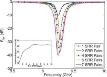
When the rejection levels presented by both filters are compared, it is observed that the SRR-based filter has a maximum rejection level of⬃40 dB, whereas it is nearly 60 dB for the CSRR-based one. This enhanced rejection level of the CSRR-based filter can be attributed to the very strong capacitive coupling between the microstrip line and the CSRR stages. As observed in Figures 2 and 4, a better rejection level is achieved using CSRRs although both filters have the same number of stages. Hence, it is predicted that the number of SRR or CSRR stages may have different effects on the overall filter response. To verify this claim, the insertion loss responses of both filter types have been investigated by increasing the number of SRR and CSRR stages starting with a single stage as shown in Figures 5 and 6, respectively. For the SRR-based band-reject filter, it is observed that with a single SRR pair (single stage) a maximum of 10-dB suppression can be obtained. This amount is close to 30 dB for two stages and about 37 dB for four stages. Adding more stages (5, 6, etc.) increases the rejection level at most to a level slightly higher than 40dB, and a saturation is
observed in the amount of maximum rejection level as seen in Figure 5, where the inset clearly shows this variation. This inter-esting behavior can be explained by the fact that in stages away from the excitation port, less loop currents are induced around the rings because of the weakened signal level and they contribute less and less to the overall rejection. As a result, adding more SRR pairs cannot enhance the performance of an SRR-based band-reject filter indefinitely. Furthermore, upon the addition of excess number of stages, the device loses its compactness and increased device length introduces more passband insertion loss, which is undesired. On the other hand, unlike the SRR-based band-reject filter, the rejection level of the CSRR-based filter increases almost linearly when the number of CSRR stages is increased as seen in Figure 6, particularly in its inset where the rejection level versus number of CSRR stages (from 2 to 10 stages) is shown. A rejection level over 80 dB is achieved with 10 CSRR stages, which is indeed very deep.
Furthermore, as the number of SRR/CSRR stages is increased, the operating frequency of both filter types is not altered much. However, the stopband characteristics of the CSRR-based filter starts to improve its behavior significantly after four stages by sharpening the stopband-to-passband transition behavior. 4. CONCLUSION
SRR- and CSRR-based band-reject filters using the same ring dimensions and the same substrate are fabricated and their perfor-mances are tested and compared. It is observed that both filter types operate almost at the same frequency, and the operating frequency does not change when the number of SRR/CSRR stages is varied. However, much wider rejection bands and deeper rejec-tion levels of CSRR-based filters attract attenrejec-tion. In particular, the stopband characteristics of CSRR-based filter change significantly and improve with the increasing number of CSRR stages.
In any case, both filter types have very high Q, both of them are very compact and fully planar. Therefore, they can easily be fabricated using planar circuit technologies, such as mechanical and photo etching techniques. This feature promises the design of very compact devices for printed-circuit board and monolithic microwave integrated circuit technologies. Especially, in the case of CSRR, because the resonators are placed on the ground plane, no extra circuit area is required and the filters are more compact. Figure 5 Rejection levels for increased number of SRR stages.
Maxi-mum rejection level versus the number of SRR stages is also given as an inset. [Color figure can be viewed in the online issue, which is available at www.interscience.wiley.com]
Figure 6 Rejection levels for increased number of CSRR stages. Max-imum rejection level versus the number of CSRR stages is also given as an inset. [Color figure can be viewed in the online issue, which is available at www.interscience.wiley.com]
The differences in the stopband characteristics of these filters can make them preferable depending on applications.
ACKNOWLEDGMENT
Authors thank the Microwave and System Technologies Division of ASELSAN for their support during the fabrication of the pro-totypes. This work was supported in part by the Turkish Scientific and Technological Research Council (TU¨ BI˙TAK) under grant no. EEEAG-105E065 and Turkish Academy of Sciences (TU¨ BA)-GEBI˙P.
REFERENCES
1. J.B. Pendry, A.J. Holden, D.J. Robbins, and W.J. Stewart, Magnetism from conductors and enhanced nonlinear phenomena, IEEE Trans Microwave Theory Tech 47 (1999), 2075-2084.
2. F. Falcone, T. Lopetegi, J.D. Baena, R. Marque´s, F. Martı´n, and M. Sorolla, Effective negative- stopband microstrip lines based on com-plementary split-ring resonators, IEEE Microwave Wireless Compon Lett 14 (2004), 280-282.
3. F. Martı´n, F. Falcone, J. Bonache, R. Marque´s, T. Lopetegi, and M. Sorolla, Miniaturized coplanar waveguide stop band filters based on multiple tuned split-ring resonators, IEEE Microwave Wireless Com-pon Lett 13 (2003), 511-513.
4. F. Falcone, F. Martı´n, J. Bonache, R. Marque´s, and M. Sorolla, Coplanar waveguide structures loaded with split-ring resonators, Mi-crowave Opt Technol Lett 40 (2004), 3-6.
5. F. Falcone, F. Martı´n, J. Bonache, R. Marque´s, T. Lopetegi, and M. Sorolla, Left-handed coplanar waveguide band pass filters based on bi-layer split-ring resonators, IEEE Microwave Wireless Compon Lett 14 (2004), 10-12.
6. G.V. Eleftheriades, A.K. Iyer, and P.C. Kremer, Planar negative re-fractive index media using periodically L-C loaded transmission lines, IEEE Trans Microwave Theory Tech 53 (2005), 1997-2006. 7. J. Martel, R. Marque´s, F. Falcone, J.D. Baena, F. Medina, F. Martı´n,
and M. Sorolla, A new LC series element for compact bandpass filter design, IEEE Microwave Wireless Compon Lett 14 (2004), 210-212. 8. J. Garcı´a-Garcı´a, F. Martı´n, F. Falcone, J. Bonache, I. Gil, T. Lopetegi, M.A.G. Laso, M. Sorolla, and R. Marque´s, Spurious passband sup-pression in microstrip coupled line band pass filters by means of split-ring resonators, IEEE Microwave Wireless Compon Lett 14 (2004), 416-418.
9. J. Garcı´a-Garcı´a, J. Bonache, I. Gil, F. Martı´n, R. Marque´s, F. Falcone, T. Lopetegi, M.A.G. Laso, and M. Sorolla, Comparison of electro-magnetic band gap and split-ring resonator microstrip lines as stop band structures, Microwave Opt Technol Lett 44 (2005), 376-379. 10. S.N. Burokur, M. Latrach, and S. Toutain, Study of the effect of
dielectric split-ring resonators on microstrip-line transmission, Micro-wave Opt Technol Lett 44 (2005), 445-448.
11. J. Garcı´a-Garcı´a, F. Martı´n, F. Falcone, J. Bonache, J.D. Baena, I. Gil, E. Amat, T. Lopetegi, M.A.G. Laso, J.A.M. Iturmendi, M. Sorolla, and R. Marque´s, Microwave filters with improved stopband based on sub-wavelength resonators, IEEE Trans Microwave Theory Tech 53 (2005), 1997-2006.
12. J.D. Baena, J. Bonache, F. Martı´n, R.M. Sillero, F. Falcone, T. Lope-tegi, M.A.G. Laso, J. Garcı´a-Garcı´a, I. Gil, M.F. Portillo, and M. Sorolla, Equivalent-circuit models for split-ring resonators and com-plementary split-ring resonators coupled to planar transmission lines, IEEE Trans Microwave Theory Tech 53 (2005), 1451-1461. 13. J. Bonache, F. Martı´n, I. Gil, J. Garcı´a-Garcı´a, R. Marque´s, and M.
Sorolla. Microstrip bandpass filters with wide bandwidth and compact dimensions, Microwave Opt Technol Lett 46 (2005), 343-346. 14. J. Bonache, F. Martı´n, F. Falcone, J.D. Baena, T. Lopetegi, J.
Garcı´a-Garcı´a, M.A.G. Laso, I. Gil, A. Marcotegui, R. Marque´s, and M. Sorolla, Application of complementary split-ring resonators to the design of compact narrow band-pass structures in microstrip technol-ogy, Microwave Opt Technol Lett 46 (2005), 508-512.
15. X. Ying and A. Alphones, Propagation characteristics of
complimen-tary split ring resonator (CSRR) based EBG structure, Microwave Opt Technol Lett 47 (2005), 409-412.
16. J. Bonache, I. Gil, J. Garcı´a-Garcı´a, and F. Martı´n, Novel microstrip bandpass filters based on complementary split-ring resonators, IEEE Trans Microwave Theory Tech 54 (2006), 265-271.
17. H.-W. Wu, Y.-K. Su, M.-H. Weng, and C.-Y. Hung, A compact narrow-band microstrip bandpass filter with a complementary split-ring resonator, Microwave Opt Technol Lett 48 (2006), 2103-2106. 18. I. Gil, J. Bonache, M. Gil, J. Garcı´a-Garcı´a, and F. Martı´n, Left-handed
and right-handed transmission properties of microstrip lines loaded with complementary split rings resonators, Microwave Opt Technol Lett 48 (2006), 2508-2511.
19. H.-W. Wu, M.-H. Weng, Y.-K. Su, R.-Y. Yang, and C.-Y. Hung, Propagation characteristics of complementary split-ring resonator for wide bandgap enhancement in microstrip bandpass filter, Microwave Opt Technol Lett 49 (2007), 292-295.
20. A.M.E. Safwat, S. Tretyakov and A. Ra¨isa¨nen, Dual bandstop reso-nator using combined split ring resoreso-nator and defected ground struc-ture, Microwave Opt Technol Lett 49 (2007), 1249-1253.
21. V.C. Bengin, V. Radonic´, and B. Jokanovic´, Left-handed microstrip lines with multiple complementary split-ring and spiral resonators, Microwave Opt Technol Lett 49 (2007), 1391-1395.
22. Ansoft Designer(TM) v2.0, http://www.ansoft.com/products/hf/an-soft_designer/, Ansoft Corporation, Pittsburgh, PA.
23. Ansoft High Frequency Structure Simulator, Ansoft HFSS(TM) v9.2.1, http://www.ansoft.com/products/hf/hfss/, Ansoft Corporation, Pittsburgh, PA.
24. R. Marque´s, F. Mesa, J. Martel, and F. Medina, Comparative analysis of edge- and broadside-coupled split-ring resonators for metamaterial design—Theory and experiments, IEEE Trans Antennas Propag 51 (2003), 2572.
© 2007 Wiley Periodicals, Inc.
LEAKY MODE DISPERSIONS OF
GOUBAU LINES
Ki Young Kim
Department of Electrical Engineering and Computer Science, Northwestern University, Evanston, IL 60201; Corresponding author: [email protected]
Received 9 July 2007
ABSTRACT: The leaky dispersion characteristics of a Goubau line
were numerically investigated for three lower-order transverse magnetic (TM) modes by determining a complex propagation constant using Davi-denko’s method. As a result, physically meaningful spectral ranges of leaky modes were found to exist below the cutoff frequency of the Goubau line. © 2007 Wiley Periodicals, Inc. Microwave Opt Technol
Lett 50: 523–525, 2008; Published online in Wiley InterScience (www. interscience.wiley.com). DOI 10.1002/mop.23136
Key words: complex propagation constant; dispersion; Goubau line;
leaky mode
1. INTRODUCTION
Waveguides with continuously open structures in a longitudinal direction have the potential to be used as a leaky wave antenna with relatively simple and inexpensive structures compared with their periodic counterparts [1]. The radiation efficiency of such guiding structures strongly depends on their loss characteristics, i.e., a low loss property guarantees a high radiating efficiency. Recently, the current authors conducted a rigorous analysis of the leaky mode characteristics of a circular dielectric rod waveguide, which has an intrinsic low loss property [2]. A Goubau line is also