INTERACTIVE REAL-TIME RF CONTROL
FOR MRI TRANSMIT CHANNELS
a thesis submitted to
the graduate school of engineering and science
of bilkent university
in partial fulfillment of the requirements for
the degree of
master of science
in
electrical and electronics engineering
By
U˘
gur Yılmaz
Interactive Real-time RF Control for MRI Transmit Channels By U˘gur Yılmaz
September 2019
We certify that we have read this thesis and that in our opinion it is fully adequate, in scope and in quality, as a thesis for the degree of Master of Science.
Ergin Atalar(Advisor)
Emine ¨Ulk¨u Sarıta¸s C¸ ukur
Beh¸cet Murat Ey¨ubo˘glu
Approved for the Graduate School of Engineering and Science:
ABSTRACT
INTERACTIVE REAL-TIME RF CONTROL FOR MRI
TRANSMIT CHANNELS
U˘gur Yılmaz
M.S. in Electrical and Electronics Engineering Advisor: Ergin Atalar
September 2019
Cardiac catheterization is one of the heavily researched areas of the real-time interventional studies in Magnetic Resonance Imaging (MRI), where elongated conductive wires are prone to excessive radiofrequency (RF) heating and track-ing of the devices might be challengtrack-ing. Previous studies have proposed several techniques for heating reduction at the conductive wire tip and device visualiza-tion, using multiple transmit channels but the software platform for real-time RF control of multiple transmit channels has been missing for interventional proce-dures. In this study, we are presenting a software framework capable of inter-active real-time RF control of MRI transmit channels and reception of dynamic images from MR image reconstruction computer. The software consists of three main programs running on three different operating systems (Linux, Windows and VxWorks) that communicate with each other over TCP/IP connection. Be-sides socket programming, multi-threading/multi-tasking is implemented for each platform along with the synchronization semaphores. The graphical user interface end is developed with Qt. Siemens’ work-in-progress tip-tracking pulse sequence (BEAT IRTTT) source code is modified to serve as the other end in our software system. The interactive real-time experiments are conducted on a copper sulfate phantom including a conductive wire. Dual-port body coil which is a product of Siemens is used as the transmit antenna and each port is driven independently. Results have shown the feasibility of the real-time RF control in the MRI, with an effective total update latency of two frames on the dynamic image-series. We believe this framework will contribute to real-time interventional procedures in terms of RF safety and catheter tracking.
¨
OZET
MR RF VURUCU KANALLARININ ˙INTERAKT˙IF
GERC
¸ EK ZAMANLI KONTROL ¨
U
U˘gur Yılmaz
Elektrik ve Elektronik M¨uhendisli˘gi, Y¨uksek Lisans Tez Danı¸smanı: Ergin Atalar
Eyl¨ul 2019
Ger¸cek zamanlı giri¸simsel Manyetik Rezonans G¨or¨unt¨uleme’de (MRG) en sık ara¸stırılan alanlardan biri olan kalp kateterizasyonunda kullanılan uzun iletken tellerin hem takibi zordur hem de radyofrekans (RF) ısınma tehlikeleri vardır. Yapılan ¸ce¸sitli ara¸stırmalar ¸coklu radyofrekans (RF) yayın dizilerini kullanarak kateter ısınmasını azalatacak ve takibini kolayla¸stıracak teknikler sunmu¸stur; fakat giri¸simsel prosed¨urler i¸cin gerekli olan ger¸cek zamanlı RF kontrol yazılım
platformu bulunmamaktadır. Bu ¸calı¸smada MRG yayın dizilerinin interaktif
ger¸cek zamanlı kontrol¨un¨u sa˘glayacak bir yazılım sunuyoruz. ¨U¸c ana program-dan olu¸san bu yazılım TCP/IP protokol¨u ¨uzerinden haberle¸serek ¨u¸c ayrı i¸sletim sistemi (Linux, Windows, VxWorks) ¨uzerinde ¸calı¸smaktadır. Soket program-lama ile birlikte her i¸sletim platformu i¸cin ¸coklu g¨orev ve semaforlar uygu-lanmı¸stır. Grafiksel kullanıcı aray¨uz¨u tarafı Qt kullanılarak tasarlanırken sis-temin di˘ger tarafı Siemens’in katater takibi i¸cin geli¸stirdi˘gi BEAT IRTTT isimli darbe dizisinin kaynak kodu de˘gi¸stirilerek olu¸sturulmu¸stur. ˙Interaktif ger¸cek za-manlı deneyler iletken bir tel i¸ceren bakır s¨ulfat fantomunda yapılmı¸stır. Yayın anteni olarak Siemens’in v¨ucut sargısının iki kanalı ayrı ve ba˘gımsız s¨ur¨ulm¨u¸st¨ur. Deney sonu¸cları ger¸cek zamanlı RF kontrol¨un¨un olabilirli˘gini tasdik ederken RF de˘gi¸skenlerinin iki ¸cer¸ceve gecikme ile g¨uncellendi˘gi g¨ozlemlenmi¸stir. Bu yazılımın ısınma g¨uvenli˘gi ve kateter takibi a¸cısından ger¸cek zamanlı giri¸simsel Manyetik Rezonans G¨or¨unt¨uleme operasyonlarında katkı sa˘glayaca˘gına inanıyoruz.
Anahtar s¨ozc¨ukler : MRG, VxWorks, interaktif, RF yayın dizisi, ger¸cek zamanlı, giri¸simsel, kateterizasyon.
Acknowledgement
There are so many people who have supported me during my graduate studies. I would like to start with Prof. Ergin Atalar who has pushed me to finish my thesis even after the long break that I had to take due to medical reasons. Without his guidance and confidence in me, I would not be able to obtain the master’s degree now. Your assistance meant a lot for me. Thank you for everything.
I also would like to express my gratitude for Prof. Emine ¨Ulk¨u Sarıta¸s C¸ ukur and Beh¸cet Murat Ey¨ubo˘glu for kindly being my jury members. Thank you for sparing your time for this and your useful inputs and discussion on the thesis. I am deeply grateful to be acquainted with you.
I am grateful to have Sinan Arıy¨urek as a friend, with whom I always have the opportunity to discuss about many programming aspects. Not only he is an enthusiastic coder but also has an immense heart. I am also glad that our lab includes Bilal Ta¸sdelen so that I can have someone to explore pulse se-quence programming with. In that regard, I also thank to my lab members:
Cemre Arıy¨urek, Alireza Sadeghi-Tarakameh, Ehsan Kazemivalipour, Reza
Ba-baloo, S¨uheyl Taraghinia, Said Aldemir, Gamze Zeynep Bilici, Ahmet Fatih
Yaprak, Mert Bozkurt. Special gratitude goes to such friends as Aydan Erc-ing¨oz, Arzu Ceylan Has, Berk Silemek, Umut G¨undo˘gdu, Volkan A¸cıkel, Elif
¨
Unal and Mustafa Can Delikanlı, who I shared so many moments together within UMRAM.
Those who had been a part of UMRAM Atalar Lab once, you are also not forgotten: Taner Demir, Koray Ertan, Safa ¨Ozdemir, Reyhan Erg¨un. Thanks for your company. I would also like to acknowledge all the other UMRAM Labs for creating a diverse environment in Aysel Sabuncu Brain Research Center.
vi
life, as you are the persons who I have shared the most common interests with. Hamidullah Tarhan, Mustafa G¨ur, and Mustafa Alano˘glu; I will never forget the support I have received from you. Serkan Sarıta¸s, Meryem Tu˘gba Pek¸sen, Ahmet D¨undar Sezer, Furkan Keskin and Cahit K¨o¸sger; we might not be physically in close range now but our friendship will always linger. Ahmet Y¨ukselt¨urk, Yusuf C¸ ınar and Ahmet C¸ ınar; thank you for being a part of the tales we share together in two different cities.
The last but not the least, I am deeply grateful to have my family for being always there for me and getting through my difficult years: my mom Hanım, the strongest woman I have ever known; my dad Zeki, the most calm person; my beautiful sister Dilek, the most skillful human being; and my little brother Taylan, the tenacious rascal that I am glad to be related to. I love you all.
Finally, I acknowledge The Scientific and Technological Council of Turkey (T ¨UB˙ITAK), B˙IDEB 2210 Program for funding me during my graduate studies. Furthermore, I thank to Li Pan from Siemens Corporate Research for sharing BEAT IRTTT source code.
Contents
1 Introduction 1
2 Overall System Architecture 6
2.1 GUI - Interactive Real-time RF Control (IRRFC) . . . 10
2.2 Tx-Console Servers . . . 13
2.2.1 Tx-Master Server . . . 14
2.2.2 Tx-Slave Server . . . 15
2.3 MPCU Client . . . 15
3 MRI Experiment and Results 25 3.1 Experiment Setup and Imaging Parameters . . . 25
List of Figures
2.1 Overall system architecture . . . 7
2.2 Software modules and network interaction paths . . . 9
2.3 Screenshot for the graphical user interface . . . 11
3.1 Prepared phantom, consisting of a conductive wire and copper sulfate solution . . . 26
3.2 Images acquired without iPAT when RF transmission done by each channel separately . . . 28
3.3 Images acquired without iPAT when both channels are used simul-taneously for transmission . . . 29
3.4 Three time points acquired with GRAPPA (R2) . . . 30
A.1 Flowchart for IRRFC . . . 41
A.2 Flowchart for Tx-Master Server . . . 42
A.3 Flowchart for Tx-Slave Server . . . 43
Chapter 1
Introduction
Real-time imaging is one of the research areas in the field of Magnetic Reso-nance Imaging (MRI), studied in different scopes. It essentially aims to capture a dynamically evolving process with fast data acquisition and reconstruction tech-niques. One of the areas of the real-time MRI focuses on the dynamicity of the vocal tract and respiratory system. In that regard, some studies conducted research on the articulation [1] and speech process [2], while some others investi-gated the velum movement [3] and the respiratory differences between phonation and breathing [4]. Yet another branch of the real-time MRI can be categorized as the non-invasive studies pertaining to the cardiovascular system [5, 6].
Another heavily researched sub-area of the real-time MRI is the interventional MRI, which encompasses different sub-branches ranging from MR-guided High Intensity Focused Ultrasound (HIFU) to catheter-based interventions. The main focus of this thesis is on the catheter-based interventions, where a long thin tube catheter is inserted and traversed along a pre-determined tract/vessel. Con-ventionally, interventional radiology (especially cardiac catheterization) has been done with the x-ray fluoroscopy. This modality can show the inserted device
operations [7]. Although the staff operating on the patient usually wears lead gar-ments to protect themselves from the ionizing radiation, prolonged use of those heavy aprons could cause orthopedic complications [8].
Real-time MRI, on the other hand, stands out as a valuable modality for inter-ventional cardiac procedures, as it does not irradiate harmful x-ray and provides best soft-tissue contrast that depicts many different abnormalities [9, 10, 11]. Un-like the x-ray fluoroscopy, MRI can yield 3D images, improving the device nav-igation. In fact, there have been numerous preclinical interventional operations successfully done with the real-time MRI such as atrial septal shunt closure [12], stent angioplasty [13], and pulmonary valvuloplasty [14]. In addition; while the catheters used in the x-ray fluoroscopy are passive, the catheters can be active in the MRI, meaning that they can be manufactured as separate receiver coils plugged into scanner electronics, acting as a separate signal channel by which determining the device location can be easier.
One drawback of the real-time MRI is that it is not as fast as the x-ray imag-ing. However, it is regarded as adequate for device navigation to have a image formation and display with at most <200 msec latency [15]. With the advances on parallel imaging techniques and fast acquisition schemes, this criterion can be well achieved.
Nevertheless, MRI suffers from two main difficulties. One of them is inherent but not limited to the interventional cardiac MRI that needs addressing. It is the radiofrequency (RF) current induced on a conductive wire when the wire is located on the non-zero electric field of the transmission, causing heating espe-cially at the tip of the wires where the electric field becomes maximum [16]. The passive catheters used with metallic guidewires for flexible navigation and all the active catheters accompany the risk of excessive heating.
The conventional MRI transmit body coil, which is a forward polarized bird-cage coil, has an electric field zero only at the center of the axial plane which in-creases linearly in radial direction; whereas a linearly polarized birdcage coil has a sinusoidal electric field variation along the azimuthal direction resulting in a zero
electric field plane at an angle perpendicular to the excitation port [17]. Safety of the long metallic devices under standard MRI transmit mode is a challenging problem, as they experience high electric field at the edges of the body. Although there are specific device-based methods [18, 19] to alleviate the RF heating issues in standard transmit mode, transmit array (TxArray) systems have also picked particular interest to ensure the RF safety of elongated conductors in MRI. For instance, there is a study where two ports of the birdcage coil, each generating a linearly polarized magnetic field and hence creating a corresponding zero electric field, are simultaneously driven with different amplitude and phase values using a TxArray system to steer the combined zero electric field onto the metallic de-vice orientation [20]. A more recent study [21] has presented an imaged based method to mitigate the RF heating at the tip of the longitudinal implants using multi-channel transmission. The study relies on the fact that the main transmit magnetic field and the magnetic field due to the induced current on a long wire cancel out each other, creating a transmit null point in the vicinity of the wire on the axial images. Using the radial and the azimuthal position of the transmit null points for each transmit channel, the induced currents can be calculated. Then the implant friendly mode can be excited by calculating the appropriate complex channel weightings that result in zero induced current on the conductive wire.
Another recent study [22] has shown the minimization of the localized RF heating at the tip of a wire inserted into a head phantom with custom-made 4-channel parallel transmission platform embedded to a commercial scanner, where each channel is independently and concurrently controllable by the platform soft-ware. Their method finds the RF shim coefficients to four independent channels by minimizing a cost function that includes the power deposition in the vicinity of the wire tip and transmit field inhomogeneity over a larger volume interest. Calculating the power deposition is not easy as there is no straightforward way of measuring E-field and/or conductivity distribution in the body. Instead, they use the electromagnetic simulation of the phantom. In another study [23], a
Although this study does not require a TxArray system, its use is not feasible for prospective interventional MRI to reduce RF heating of catheters since the rapid rotation of a body-coil synchronized with the real-time procedure is not easy. Moreover, this technique may not solve a particular case where the implant wire is not confined into a plane but rather turns inside the patient. In such case, the safety condition can only be met by elliptical polarization rather than linear polarization.
The other drawback with interventional cardiac MRI and other needle-based interventional MRI is the difficulty of device tracking. Passive catheters create signal void in standard anatomical imaging which hinder their visualization in low intensity background. Although susceptibility markers can be augmented with passive catheters [24] to increase the signal void around the marker for better visualization, the devices are visible within the imaging plane and it becomes a challenging task when the device needs navigation through complex vascula-ture [15]. Active catheters; on the other hand, function as separate receiver coils that make their visualization much easier [25]. However, extra cable connections to MRI scanner aggravate the handling of the catheter and the long conductive cables carry the risk of excessive RF heating. Yet, a study [26] has shown a differ-ent technique to enhance passive devices using the reversed polarization transmit mode. Since the spins are only sensitive to the forward polarized transmit field, reversed polarization will not cause any excitation. The reversed polarized field can still couple to linearly polarized devices such as the passive catheters and the induced current on the device will cause a linearly polarized field in the vicinity which can excite the spins thereby, as a linearly polarized field can be decomposed into forward and reversed polarized components. With this method, only-device images can be acquired separately and registered onto anatomical images. Such polarization control can only be done by controlling more than one linearly po-larized transmit coil.
TxArray system; therefore, is becoming more and more significant. Not only it is required to mitigate the non-uniform transmit profile in high magnetic fields due to shorter wavelengths [27, 28], it is also important in needle-based procedures for aforementioned reasons. However, as the device is pushed through a vessel/tract
in an interventional operation, the transmit channels of TxArray system must be dynamically updated with new coefficients. Although how those input coefficients can be calculated real-time is another area that should be studied, the need for such a real-time RF control is obvious.
In this study, we developed a software incorporated to TxArray system of 3T Tim Trio Scanner (Siemens Healthcare, Erlangen, Germany), where a remote operator can steer the RF parameters of 8 transmit channels independently in real-time. This thesis builds on a previous work [29], which does not only serve as a software framework that can be embedded with prospective real-time dynamic RF safety algorithms but can also provide a tracking control over passive catheters that can be visualized better in reverse polarized transmit mode.
The rest of the thesis is broken down into four parts. In the second chapter, the overall system architecture will be outlined. Each subsystem containing a part of our software code will be walked through in the subsections. The imaging parameters and phantom used for the experiments will be explained in the third chapter, along with the results of the experiments. In the fourth chapter, a few points will be discussed about our software design and the experiment results, followed by conclusions. Finally, in the Appendix, flowchart for each software module is provided.
Chapter 2
Overall System Architecture
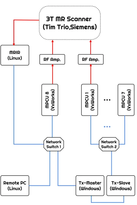
Before going into detail on how the software we constructed interacts with the MR scanner, it is best to first give a general outline on TxArray architecture relevant to the thesis and how our system integrates with it (Figure 2.1). TxArray we use is a part of 3T Tim Trio Scanner (Siemens Healthcare, Erlangen, Germany), which has 8 independent RF transmit channels.
Each channel is controlled by a dedicated hardware unit called Measurement and Physiological Control Unit (MPCU) with a Pentium III 1260 MHz processor, and a 256 MB RAM. Operating system running on an MPCU is VxWorks (version 5.5, Wind River Systems), a real-time operating system (RTOS). Main MPCU (let’s call it MPCU 8) controls and provides required data to all scanner hardware (gradient chains, receiver chains, etc.,) except the RF amplifiers (Analogic, 8 kW) for the other 7 channels. Rest of the MPCUs control only the RF amplifiers assigned for them. MPCU is where the dynamic sequence library runs, which essentially controls the timings of different hardware to generate and acquire the MRI signals.
Acquired MRI signal is processed in the MR Image Reconstruction (MRIR) computer (Quad AMD Opteron processor, 16384 MB RAM). Operating system installed on MRIR is SUSE Linux. MRIR runs Image Calculation Environment
3T MR Scanner
(Tim Trio,Siemens)
MRIR (Linux) Remote PC (Linux) RF Amp. RF Amp. MPCU 8 (VxWorks) MPCU 1 (VxWorks) MPCU 7 (VxWorks) Tx-Master(Windows) (Windows)Tx-Slave
Network
Switch 1 NetworkSwitch 2
(ICE) program that sets up the necessary image reconstruction pipeline. The reconstruction pipeline is programmable and editable by the user. Online recon-structed images are sent to host computer (Tx-Master) for further processing if necessary and a remote computer if required.
There are two operator computers (Dual Pentium IV, 4096 MB RAM) : Tx-Master and Tx-Slave, both installed with Windows XP. Tx-Tx-Master is the main host computer that prepares and checks the sequence library before sending it to the MPCU 8. It has also a dedicated network connection to the MRIR, as mentioned above. Tx-Slave; on the other hand, provides the sequence library to the MPCUs from 1 to 7. Tx-Slave and MPCUs 1,...,7 have an isolated sub-network from the Tx-Master, MPCU 8 and MRIR. Nevertheless, Tx-Slave and Tx-Master communicate with each other via a separate Ethernet crossover cable.
The system allows a remote PC to be plugged into the same sub-net as MPCU 8, MRIR, and Tx-Master. This PC in particular runs the Graphical User Interface (GUI) end of our software. The only restriction for the PC is that it should be installed with Qt with a version of at least 5. Note that the other end of our program runs on the MPCUs, where both ends communicate with each other through the server programs we wrote, which run on Tx-Master and Tx-Server computers.
Finally, it is up to the user how many of the RF channels one wants to uti-lize at the same time. Our software allows independent control of all of the 8 channels during the same scan. For our experiments though, we used Siemens birdcage body coil where we drive the 2 ports independently; hence, we used only 2 channels.
Please refer to the Figure 2.2 for the rest of this section. This figure illustrates the three different programs we wrote that make up the whole software (GUI, Tx-Servers, and MPCU Client Code), the threads/tasks for each of them and how they interact with each other via TCP/IP protocol. Note that the image reconstruction pipeline is Siemens’ software and we need to configure it properly
imafinish imasend Image Reconstruction Pipeline
MRIR
BEAT-IRTTTMPCU
8
MPCU Client (Spawned Task) Dynamic Sequence Library BEAT-IRTTTMPCU
4
MPCU Client (Spawned Task) Dynamic Sequence Library Worker Thread GUI Thread IRRFCRemote
PC
Worker Thread Main Thread Tx ServerTx
Master
Worker Thread Main Thread Tx ServerTx
Slave
"MR images" "RF Paramters"so that real-time MR image data (plus the metadata) can be transferred over TCP/IP (see the last paragraph of GUI section).
2.1
GUI - Interactive Real-time RF Control
(IRRFC)
This end is written in C++, using Qt libraries of threading, user interface and socket programming. It consists of two threads. The main thread is responsible for user interaction and sending out the last played RF parameters to MPCUs via a TCP/IP connection made to the server program running on Tx-Master. The second thread sets up a TCP/IP server that listens on connection requests from MRIR and starts receiving MR images once connection is accepted. Any message transfer between two threads are done via Qt signal-slot mechanisms.
Graphical User Interface as seen in Figure 2.3 has several Widgets, handled by MyWindow class. The top-left label in red shows the connection status with Tx-Master. Then comes the widgets pertaining to the phase and amplitude settings for 8 channels. For each channel, there are 2 dial buttons (left one for amplitude, right one for phase) and 2 spin-boxes right below each dial button. Spin-boxes are read-only and show the current amplitude/phase values numerically. The dial buttons; however, are editable by the user. As seen in the figure, Tx8 and Tx4 channels are active, while others are disabled. One can set the active channels to be worked with, which can be up to 8, by setting the m currentMask member variable in MyWindow class. It is an 8 bit flag, where the highest bit shows the 8th channel and lowest bit shows the 1st channel. To activate the 8th and
4th channels in this figure, m currentMask was set to 10001000 (binary) = 136 (decimal). The panel on the right is the area for MR images received from MRIR to be displayed. And the text-edit panel at the bottom is also read-only and for showing any kind of error/update messages related to network connections. The square brackets at the beginning of each message shows which connection it is
related to (can be either MRIR or MPCU). For example for the Figure 2.3, it says the client connection to Tx-Master is established but the server to listen on MRIR connection has failed.
MPCUSocket class deals with the TCP/IP connection to the Tx-Master server. It is implemented by inheriting the QTcpSocket class and socket reads/writes are done asynchronously. Events for this class are dispatched by the main GUI thread. In case of connection failure, exponential back-off algorithm is implemented for a maximum connection request of 4 times in a row. For each RF update by the user, a packet of 24 bytes (amplitude, phase and channel number) is sent to Tx-Master. Although sending a small chunk of data at each time reduces the network efficiency, it is necessary for such a real-time application. For that reason, the Naggle algorithm is disabled with LowDelayOption. The active channels must be set by the user in the code before the scan, as mentioned in the previous paragraph. In case of shutdown of the IRRFC, phase value of 400 is sent to Tx-Master, which is the code for client disconnection. Also, it should be noted that the m txMasterHost and m txMasterPort member variables in the constructor should be set with the IP address and port number of Tx-Master server by the user.
MrImDisplay class is a wrapper around QLabel class. It represents the image area on the right of the GUI. It overrides ”mouse pressed” event and catches the clicked pixel indices, and fires a signal to the MyWindow with the pixel information. Currently; however, MyWindow ignores this signal. This is for a future functionality.
Object creation for MRIRSocket class is done in the main thread by the My-Window but this object is moved to the worker thread in order not to block GUI when dealing with the reception and processing of large MR images. This class inherits the QTcpServer class and sets up the server that will listen to connec-tion request coming from MRIR. Once connecconnec-tion is accepted, MR images with preceding header data are received real-time. MRIR first sends 64-bit data be-fore each image, that tells the sizes of the header and image data (first 32-bit stores the header size, the rest stores the data size). In this thesis, the header is
discarded and the global variables image nX and image nY define the expected dimensions of the image in horizontal and vertical directions respectively. When the first received 64-bit is zero, it means a disconnection request by the MRIR, and therefore same packet is sent back to the MRIR for disconnection acknowl-edgement. MRIRSocket class has a QImage member variable (m image) of 8-bit gray-scale format. With the first received MR image, the whole buffer is traversed first to find the maximum pixel value. This is needed to convert the 16-bit MR image data to 8-bit representation for display. After filling in the QImage data, it is signaled to the main thread with Qt::QueuedConnection option. MyWindow transforms it to the QPixel in order to paint it on the GUI panel. Note that, since QPixel is not re-entrant (meaning that it can not be used in non-GUI threads), a QImage object has to be used as a parameter for inter-thread signaling.
Finally it is of importance to mention about prerequisite for real-time MR image reception from MRIR. By default, there is no real-time image transfer over a TCP/IP connection. In order to enable this option, ICE program configuration file has to be modified accordingly where the remote server’s (the PC) IP and port numbers are specified. Morever, a particular ICE functor dynamic library for real-time data export must exist. Please refer to the ”ICE User’s Guide: Manual for ICE programmers (V 0.74)”1 for a detailed explanation on the ICE functor
and configuration file set-up.
2.2
Tx-Console Servers
MR operator computers are generally fixed with strict firewall settings. Thus, it is worth mentioning that before the following console applications are run on the Tx-Master and Tx-Slave computers, the firewall must be turned off for the port numbers that these two server are listening on. Otherwise, the indirect TCP/IP
2.2.1
Tx-Master Server
Running on the TX-Master computer, this server program is coded in C using Windows API for synchronous socket programming, threading and synchroniza-tion of shared data between threads. The code consists of a main funcsynchroniza-tion and a worker thread created from the main function. Initially, the main function checks the socket library compatibility. If there is no compatibility issue to use the socket library, it goes on creating a socket to listen for the TX-Slave server con-nection. Only after TX-Slave server has connected, the Tx-Master server handles the connection with 8th MPCU client and IRRFC client.
Connected with the Tx-Slave server, the main function invokes a thread to accept IRRFC and main MPCU connections. The thread is in an infinite loop (unless the program is terminated), listening to the aforementioned clients for new connections. Since the clients can close and start up again at any time, this worker thread replaces new connections with the old ones if such requests are received from the client ends.
Meanwhile, the main function proceeds to listen in an infinite loop for data packets to be received from IRRFC client, if connected. For each received data, the packet is either forwarded to Tx-Slave or MPCU 8, depending on the target mpcu number. Moreover, the sockets regarding MPCU 8 and IRRFC client are destroyed if the received data is coded for IRRFC client termination by user (i.e. phase value of 400.0, as mentioned in the previous section). In that case, same data is sent to Tx-Slave so that it can close the other MPCU client sockets. Even though the connections from client to servers are terminated, the TX-Slave and TX-Master servers carry on listening for new connections, in case a new sequence protocol is started.
2.2.2
Tx-Slave Server
Required for establishing the linkage between IRRFC client and the 7 MPCUs other than the main one, this server runs on Tx-Slave, coded with C using Win-dows API’s synchronous socket programming, threading and synchronization of shared data between threads. Like the TX-Master server, this server also consists of two threads: the main function (main thread) and the thread created by the main function (worker thread). Main function initially requests connection to TX-Master, and if successful, it proceeds to create a worker thread for MPCU connections.
The worker thread runs in an infinite loop. The loop basically listens to the new connections that might be requested by the MPCUs from 1 to 7. When a new connection request arrives, old sockets are dropped off and replaced with the new ones. When the main function terminates, the thread exits the loop by checking the status of main function at the first step of each loop entrance. The data synchronization between main thread and worker thread is done using Windows Critical Section Objects. The same synchronization method is also used in TX-Master server code.
The main function in the mean time listens to the TX-Master socket for any incoming data. The received data packet is sent to the target MPCU according to the mpcuNo of the data packet. Besides, as in Tx-Master server, each received data is checked whether the phase entry has the value 400.0, which means user termination. If it does, the same data packet is sent to every connected MPCUs, and the sockets for the connected MPCUs are destroyed in TX-Slave server side.
on/off or output a specific value at particular time periods, to generate the MR acquisition data. The timings and the output levels of the controlled hardware determines the MRI pulse sequence. The pulse sequences can be programmed in C++ with a Siemens software called Integrated Development Environment for Ap-plications (IDEA), baseline VB17A. Ported with a Tornado g++ cross compiler, two targets are compiled in IDEA for each pulse sequence code: one executable (for Windows) to run on the MR operator computers (Tx-Master, Tx-Slave) and the other one (for VxWorks) to run on the MPCU.
Each pulse sequence; in essence, must have at least four mandatory entry points (”init”, ”prep”, ”check”, ”run”) to successfully execute on the Siemens
MR scanner. (Please refer to the IDEA Sequence Programming Course Notes2
provided by Siemens for the accurate function declarations). These functions are called by the system at different phases of the protocol. The Windows target is called for its ”init”, ”prep” and ”check” entry points to make sure the protocol is consistent and does not exceed hardware limits before MPCU executes the VxWorks target by calling its ”init”, ”prep” and ”run” functions. The main role of those functions are:
• ”init” function initializes all sequence parameters
• ”prep” function tries to prepare a consistent/non-conflicting protocol start-ing from the initial parameters
• ”check” function checks for any gradient overflow in physical coordinates
• ”run” function plays out the pulse sequence kernel that dictates the timings and output levels
For our study, due to being suitable for real-time applications, we mod-ified the source code of a work-in-progress pulse sequence program called BEAT IRTTT [30] (Siemens Corporate Research, USA), developed for tip track-ing procedures. It offers two rapid imagtrack-ing kernels that a user can chose from: 2This is property of Siemens Medical System and may not be publicly available. Contact
TRUFI and fast GRE. Into this sequence source code, we embedded our client code which is responsible for receiving the rf parameters coming from IRRFC via TCP/IP and telling the BEAT IRTTT kernel to update the RF member attributes accordingly. Due to confidentiality, we will walk through our code seg-ments inserted into different parts of the product source code in detail without disclosure of the BEAT IRTTT source code3.
First of all, at the begining of the header file of the pulse sequence, we add the declaration of the RF data structure sent/received through the network connec-tion as follows: typedef s t r u c t socketTCPData { double chanNo ; double p h a s e ; double amp ; } socketTCPData ;
chanNo tells which MPCU this data is meant for, which can be between 1 and 8. amp is the amplitude scale that can take between 0.0 and 1.0. The phase is the relative phase added to the RF object’s initial phase. Although the chanNo and phase should be integer type, they are set as double because this same data structure is also defined in other software modules (IRRFC and Tx-Servers) that run on different operating systems, which might add zero padding between the structure variables if they take different sizes on the memory as double and integer would.
Then, to the kernel header file of the pulse sequence, we add the following four member variables into the class declaration.
double m i n i t i a l R F V o l t a g e ; double m i n i t i a l R F P h a s e ;
m initialRFVoltage holds the initially prepared transmit voltage, m initialRFPhase holds the initially prepared transmit phase. These two member variables are needed because the incoming RF packet from remote PC tells the relative am-plitude [0.0 - 1.0] and relative phase value [0 - 360]. m spawnedTaskID holds the task id of the spawned task, which is needed in case of task deletion. Finally, m lastRFUpdate holds the last RF packet seen by the sequence kernel. This last member variable is important because the kernel restores the initially prepared values at each phase encoding line acquisition. Therefore, we need to re-update with the last RF parameters before each line acquisition.
The rest of the modification is done to the kernel source file. First, at the beginning of the source file, we included all the necessary header files for multi-tasking, semaphore and socket programming as follows:
#i f d e f VXWORKS #include ” vxworks . h” #include ” s o c k L i b . h” #include ” s t r i n g . h” #include ” t a s k L i b . h” #include <s t d i o . h> #include ” s t d l i b . h” #include ” semLib . h” #include ” i n e t L i b . h” #include ” h o s t L i b . h” #include ” s y s L i b . h” #include ” t i m e . h” #endif
Almost every inserted code segments (except the initialization and assignment of the member variables) must be enclosed with #ifdef VXWORKS ... #endif preprocessor directives, as the real-time execution of the pulse sequence kernel is only done in MPCUs. Therefore, it is best to make the functionality avail-able for only the VxWorks target. To mention about the most important ones,
”taskLib.h” is for task-spawning, ”semLib.h” is for semaphores, and ”sockLib.h” is for socket programming. Note that some of those VxWorks related header files do not come with the default IDEA installation4.
After including the headers, global variables and declaration of the function to be spawned as a new task must be placed before the kernel’s member function definitions. #i f d e f VXWORKS s t a t i c void taskClientMPCU ( ) ; s t a t i c SEM ID semMutex ; s o c k e t D a t a sharedRFParam ; #endif
taskClientMPCU() is the function which will be task-spawned, receiving the in-coming RF coefficients over the network connection. It has to be declared at the top of the file before the BEAT IRTTT kernel source code. semMutex is the semaphore that allows the mutual exclusive access of the shared data between main task and the spawned task. It is from the VxWorks API. sharedRFParam is the shared data between the two threads, via which the kernel code rf attributes are updated accordingly.
The inserted member variables in the header file should be initialized. The best way is to do it in the member initialization list as follows:
m i n i t i a l R F V o l t a g e ( 6 0 . 0 ) , m i n i t i a l R F P h a s e ( 0 . 0 ) , m spawnedTaskID ( 0 )
values are not significant. However, m spawnedTaskID having a initial value of 0 is for a reason, as it means no task has been spawned yet. Again, note that this part is not enclosed with #ifdef VXWORKS ... #endif directive, since they are also member variables in the Windows target.
Next comes the initial assignment of one member and the two global variables. We code the following segment at the end of the constructor.
m lastRFUpdate . amp = 1 . 0 ; m lastRFUpdate . p h a s e = 0 . 0 ; m lastRFUpdate . chanNo = 8 . 0 ; #i f d e f VXWORKS sharedRFParam = m lastRFUpdate ; semMutex = NULL ; #endif
First the rf structure related member variables are assigned. The shared global data (sharedRFParam) can be safely assigned first, as the worker task has not been spawned yet, so there is no data integrity problem. Then the semaphore is assigned to NULL as it means the task has not been spawned yet. This is important as we will see why in the upcoming code segments. Only the global variable assignments are enclosed with the #ifdef VXWORK ... #endif direc-tives, since the member variable is also defined for Windows target in the header file, as mentioned before.
Before the execution of the kernel, the initial values for transmitter voltage and phase must be stored. This must be done after the rf pulses are prepared in ”prep” function of the kernel. We put the following two lines at the end of the ”prep” function.
m i n i t i a l R F V o l t a g e = k e r n e l R F P u l s e . g e t T r a n s m i t t e r V o l t a g e ( ) ; m i n i t i a l R F P h a s e = k e r n e l R F P u l s e . g e t I n i t i a l P h a s e ( ) ;
Note that kernelRFPulse is a generic name denoting the rf pulse member vari-able. This should be edited with the actual name of the rf member varivari-able. Again, this chunk of code is not enclosed with the #ifdef VXWORKS ... #endif preprocessor directives, since m initialRFVoltage and m initialRFPhase are the member variables defined for the Windows target as well.
Then comes the resource allocation and task-spawning. The following chunk of code is inserted at the beginning of ”run” entry-point of sequence kernel.
#i f d e f VXWORKS
i f ( semMutex == NULL && m spawnedTaskID == 0 ) {
i f ( ( semMutex = semBCreate ( SEM Q FIFO , SEM FULL) ) == NULL ) {
p r i n t f ( ” [ BEAT IRTTT : : run ] Semaphore c o u l d n ’ t be c r e a t e d ! I n t e r a c t i v e RF s t e e r i n g i s o f f ! \ n” ) ; // f o r DEBUG! }
e l s e {
m spawnedTaskID = taskSpawn ( ” tClientMPCU ” , 1 1 0 , VX FP TASK , 2 0 0 0 0 , (FUNCPTR) taskClientMPCU , 0 , 0 , 0 , 0 , 0 , 0 , 0 , 0 , 0 , 0 ) ; i f ( m spawnedTaskID == ERROR ) {
p r i n t f ( ” [ BEAT IRTTT : : run ] C l i e n t t a s k c o u l d n ’ t be spawned ! \ n” ) ;
f f l u s h ( s t d o u t ) ; }
The global semaphore resource is checked first and if it has not been allocated yet, then a binary semaphore is created with SEM Q FIFO option and SEM FULL flag. FIFO queue option is used since there are only two tasks that will request access to the shared data (the sequence kernel and the spawned task). Therefore there is no need to create a priority queue for only two tasks, which could have been done by using the SEM Q PRIORITY option that would have extra over-head and hence would be slower. Only if the semaphore is successfully allocated, task-spawning will be done. The first four parameters show the name of the task, priority, task option, and stack size in bytes; respectively. The priority is cho-sen as 110. Although lower number might make this spawned task gain higher priority for the CPU scheduler, the other high priority tasks related to MR data acquisition might have to wait more before the CPU is allocated for them, which is not desired in an MRI scan. The option VX FP TASK is used to execute the task with floating point co-processor support. If the task-spawning has resulted in error, then the real-time parameter update functionality will be off.
In the same ”run” function of the kernel, update of the rf parameters with the last received data is done just before the kernel is about to play out its next phase encode line acquisition, as seen in the following lines of codes.
#i f d e f VXWORKS
i f ( ( semMutex != NULL ) && ( semTake ( semMutex , NO WAIT) == OK ) ) { m lastRFUpdate = sharedRFParam ; semGive ( semMutex ) ; } k e r n e l R F P u l s e . s e t T r a n s m i t t e r V o l t a g e ( m i n i t i a l R F V o l t a g e ∗ sharedRFParam . amp ) ; k e r n e l R F P u l s e . s e t I n i t i a l P h a s e ( m i n i t i a l R F P h a s e + sharedRFParam . p h a s e ) ; #endif
semaphore is not ready, then it should bypass the update and go on with the most recent update values, because a halt on real-time event instruction will cause the scanning stop. For that reason, NO WAIT option is used with semTake() function. Nevertheless; if the semaphore is available, it is taken and rf attributes are re-updated and semaphore is released back.
Finally, all resources must be handled and released in the destructor. We add the following code inside the destructor of the kernel.
#i f d e f VXWORKS
i f ( semMutex != NULL ) {
i f ( semTake ( semMutex , s y s C l k R a t e G e t ( ) ) == ERROR ) {
p r i n t f ( ” [ BEAT IRTTT : : Dtor ] The semaphore w i l l s t i l l be d e l e t e d a t r i s k ! \n” ) ;
f f l u s h ( s t d o u t ) ; }
s e m D e l e t e ( semMutex ) ; semMutex = NULL ;
p r i n t f ( ” [ BEAT IRTTT : : Dtor ] Semaphore i s d e l e t e d ! \ n” ) ; f f l u s h ( s t d o u t ) ; t a s k D e l a y ( 1 0 ) ; i f ( m spawnedTaskID > 0 ) { i f ( t a s k D e l e t e ( m spawnedTaskID ) == ERROR ) {
p r i n t f ( ” [ BEAT IRTTT : : Dtor ] Couldn ’ t d e l e t e t h e spawned t a s k ! \ n ” ) ;
} e l s e {
} }
#endif
If there is a valid semaphore, this code segment will delete it first. But in case the spawned task is holding the semaphore, it tries to acquire it (by semTake() function) within 1 second timeout, specified with second argument to the sem-Take() function. The sysClkRateGet() gives the number of clock ticks in 1 second, and the second parameter of semTake() expects the number of ticks as time-out. If acquiring of the semaphore fails, the graceful deletion is bypassed and the semaphore is destructed while the other task is still holding it. Then the spawned task is deleted if there is one indeed, which can be checked with the value of m spawnedTaskID.
Lastly, the taskClientMPCU() function to be task-spawned is written in C and uses POSIX API for socket programming. Connection attempt to the Tx-Server is made with a timeout value of 5 seconds. If connection is successful to the Tx-Server, it first sends its mpcu number to the Tx-Server so that it can be registered as an active channel in the server. Then, in an infinite loop, the mpcu client re-ceives the incoming TCP packets and updates the shared global data accordingly. One thing to note is that while trying to acquire the binary semaphore before shared data update, 1 second timeout time is used while invoking the semTake(). If in 1 second the semaphore is still not available, then real-time interaction is regarded as failed, hence socket is closed and task is returned. One can change the timeout value as desired for their own application. This is a matter of how ”real-time” the system is specified to be. It should also be noted that, before updating the shared data, the phase value of the rf packet is checked first. If it is 400.0 (which is a code for disconnection request made by the remote end), the socket is closed and the task is returned as requested by the user.
Having laid out the design procedures and functionality of the modules, next chapter will explain how to kick off this real-time interactive software in the MRI, along with the other information regarding the experiment set-up.
Chapter 3
MRI Experiment and Results
3.1
Experiment Setup and Imaging Parameters
Experiments are done on a custom-made phantom, using TxArray system of 3T Tim Trio Scanner (Siemens Healthcare, Erlangen, Germany). A Tupperware box (23x15x13 cm3) is drilled on lateral sides and a wire of 0.8 mm diameter and 26
cm length is inserted and glued (Figure 3.1a). The position of the drill point is chosen 32 mm from bottom, 45 mm from side surface in that the wire can experience electric field to create visible image artifact.
Then a copper sulfate solution (CuSO4) is prepared with 2.5 liters of water,
3.75 gram CuSO4, 5 gram NaCl, and 25 gram hydroxyethyl cellulose (HEC).
CuSO4 is used to shorten the longitudinal relaxation, NaCl is used for loading,
and HEC is used to enhance the homogeneous mixture (Figure 3.1b).
(a) Empty phantom with wire in-serted
(b) Phantom filled with copper sul-fate solution
Figure 3.1: Prepared phantom, consisting of a conductive wire and copper sulfate solution
sequence) is selected and run with two different sets of imaging parameters, as follows:
• Parameter Set 1: no iPAT
Parallel imaging is turned off. FOV: 200x200 mm2, Image Matrix: 128x128, Slice: Axial, Slice Thickness: 10 mm, TE: 2 msec, TR: 573.64 msec (image acquisition time).
• Parameter Set 2: GRAPPA R2
GRAPPA with acceleration rate 2 is selected. Number of auto-calibration lines: 24, TR: 344.84 msec (iamge acquisition time). Other parameters are kept same as set 1.
The frame rate is an important parameter for real-time imaging. With the first parameter set, image rate is slower ( about 2 frame/sec), whereas with the second parameter set the image rate is bumped up to about 3 frame/sec thanks to parallel imaging. Siemens’ product image reconstruction pipeline is used for data reconstruction. The reason why the first set is also used will be obvious in the Results section. Also note that in BEAT IRTT, TR is denoted as the total time for the whole acquisition, not the acquisition of one phase encoding line.
After preparing the sequence on Master, the sequence is dumped to the Tx-Slave using the ”Dump Last Protocol” batch command that is available on the start-up menu of the Tx-Master. The dumped protocol is opened from Tx UI window and applied to the channel 8th and 4th. However before starting the
sequence on the Tx UI, first Master server is started, followed by the Tx-Slave server. After master-slave connection is successfully done, IRRFC software is run on a remote PC plugged into the sub-net of MRI. Finally, the sequence is started on the Tx UI window of the Tx-Slave and real-time RF interaction on two channels is recorded.
3.2
Results
First, results for the Parameter Set 1 will be presented. Fig 3.2a shows the image acquired without GRAPPA when the 8th channel is turned on while 4th channel is turned off, and Fig 3.2b shows vice versa. As seen from the images, the trans-mit null point around the wire is different for each case as expected. Coupling between 8th channel and wire resulted in a transmit null region at left-posterior
to the wire, whereas it is left-anterior for 4th channel. It is also noticeable that
4th channel image is overall darker than the 8th channel. In an another experi-ment, we measured the forward and reflected powers via a DICO for each cable separately, when driven by the same amplifier and connected to same port, and it turned out that the cable we used for 4th channel originally forwards 45% less
power than the other cable. Therefore it generates less B1 field for the same input
power and that is why the image intensity is lower. At the same time, Fig 3.2b shows the visibility enhancement in the case of reversed polarized transmit mode.
(a) Transmit channel 8 only (b) Transmit channel 4 only
Figure 3.2: Images acquired without iPAT when RF transmission done by each channel separately
Figure 3.3 shows images when two rf channels are transmitting simultaneously with same amplitude scaling but different phases. It shows the transmit null point can be steered in real-time by playing with the rf parameters. As transmit null position hints about the induced current on the conductive wire, the result of this experiment shows that our software platform can detect the artifact change dynamically and hence it can be incorporated with image-based artifact reduction algorithms to ensure the real-time RF heating safety.
Figure 3.4 shows three different time points when images are acquired with GRAPPA (Parameter Set 2). The image on the left (Fig 3.4a) is taken at the beginning of the scan, before any RF interaction is made. The other two images are acquired after RF parameters are played. As seen from the images, the images in the middle (Fig 3.4b) and on the right (Fig 3.4c) display great reconstruction artifacts, while the first one is artifact-free. The reason is when the GRAPPA auto-calibration signal region is acquired, the transmit profile is same as the profile with the first one. Therefore, the estimation is coherent. However, with the alteration of the transmit profile, the GRAPPA estimator starts to fail and results in artifacts seen in the figure. In addition, extra dark regions start to appear on the right image (right and left of the phantom). These regions are the
(a) Concurrent transmission with rela-tive phase of 121◦
(b) Concurrent transmission with rela-tive phase of 239◦
Figure 3.3: Images acquired without iPAT when both channels are used simulta-neously for transmission
area in which B1 field becomes reverse-polarized, by which spins are not excited.
It can be stated by looking at the dial-box values on the GUI that this specific profile for that phantom orientation seems to form when the input amplitude ratio of the two port of body coil is 0.65 and phase difference is 51◦.
(a) Image at initial time point: no GRAPPA arti-fact
(b) Channel eight
phase modified: visi-ble GRAPPA artifacts
(c) Reverse polarization towards lateral sides: vis-ible GRAPPA artifacts Figure 3.4: Three time points acquired with GRAPPA (R2)
Chapter 4
Discussion and Conclusion
The most important thing of the real-time imaging is the frame rate. Slow data acquisition and reconstruction schemes can not capture the dynamics of the pro-cedure well. Therefore, parallel imaging techniques that reduce the acquisition time at the cost of the reconstruction time are preferred. However, the results shown in this thesis question the accuracy of the reconstruction when the trans-mit profile is steered during the real-time procedure, as the GRAPPA weightings found in the beginning of the scan highly coupled with the corresponding transmit profile and when RF input coefficients played out during the scan, reconstructed images start to yield ghost artifacts.
Another thing worth discussion is the latency of the system. It is best tested when one amplitude is switched at a single step. The image intensity (and profile) changes in at most 2 frames. The dynamics of it depends on at which phase encoding line the sequence kernel is playing out at the time the RF update is received. If the kernel has not started the acquisition of the next measurement (image) but is very about to, then the latency is about 1 frame. However, if the sequence has just started playing the new measurement acquisition, then the RF
ghost artifact. Moreover, we can report that the latency is inherently bounded by the protocol acquisition and image reconstruction times (which is about hundreds of milliseconds), compared to which our system’s RF data packet (which is only 24 bytes) transmission latency over the network is negligible.
As for the software aspect of the thesis, the client code inserted into the BEAT IRRTTT source code uses a binary semaphore for the mutual exclusion data access between the sequence task and the spawned task. VxWorks pro-vides more specialized semaphore for that purposes, called ”mutual exclusion semaphore” that can be created with semMCreate(). It provides options that ensure safety in case of two problematic situations:
1. Priority Inversion: This problem is inherent to the priority based task schedulers like that of VxWorks. It happens when a highest priority task waits for a resource that has been already acquired by a lowest priority and when a middle priority task that has no business with the resource in question sweeps in and preempts the lowest priority. In that case, while the middle priority task uses the CPU, the highest priority has to wait in PENDING state, which is semantically against the purpose of the pri-ority based scheduler and might cause drastic system failure in particular situations.
2. Task Deletion: This problem arises when a task tries to delete another task while the second task is holding a resource. If the task gets deleted, then the resource would never be released and the other tasks waiting for the resource would wait indefinitely.
With semMCreate(), one can pass to the argument SEM INVERSION SAFE and SEM DELETE SAFE options and get around those two problems, which are not provided by the binary semaphore library. However, the reason why we use the binary semaphore is the sequence kernel is never waiting on the semaphore (as explained in the MPCU Client Code section) and there is no situation that Priority Inversion abnormality occurs. Moreover, the semaphore is used by only two tasks (the sequence kernel task and the spawned task). Even if the sequence
kernel forces the deletion of the spawned task, there is no other task that uses the semaphore and the semaphore will be destroyed with the destruction of the sequence kernel task. On the other hand, the binary semaphore is simpler in terms of system kernel implementation and comes with lighter overhead and therefore much faster than the mutual exclusion semaphore. Thus, the best semaphore for our design is to go ahead with the binary semaphore instead of the mutual exclusion semaphore.
In addition, as one may expect, usually resource allocation is done in the constructors and released in the destructors; one of the most powerful concepts for C++ programmers. However, the binary semaphore in the MPCU client code is created in the ”run” function of the sequence kernel, not in the constructor. The reason is before the ”run” function, the sequence must pass the ”init”, ”prep” and ”check” entry-points and if one of them fails and if the semaphore allocation and task-spawning is done in the constructor, they would be done in vain as the sequence is not going to be run at all. This might be a problem for example if reconstruction pipeline cannot be prepared successfully and the MPCUs other than the 8th one will not be notified about the problem and their semaphores
and tasks might end up dangling. For that reason it is best to do all of these at the beginning of the ”run”, where we can be sure the sequence has passed the previous phases.
This software needs application based algorithm modules that can be added on the IRRFC code to be fully functional for interventional MRI, which can be image-based wire coupling decoupling algorithms for real-time safety applications or B+1-based tracking algorithms for ICRF catheter visualization. Specifically, in the present of B+1 maps, the user can set reverse polarization to enhance device visibility, by clicking on the desired region. Furthermore, with such transmit maps, homogeneity algorithms can be applied on IRRFC side to reduce intensity deviation around the conductive device to ensure RF safety. However, current
As stated earlier, the software can handle control of multiple transmit channels (not only two) but in this thesis we only worked with two because of lack of the transmit coil (product body coil has dual port). In our research center, custom-made eight channel transmit coils are being manufactured and this software will be tested on them as well.
In conclusion, we have shown the feasibility of a real-time RF control software system that can work on multiple RF channels simultaneously. The framework can be incorporated with fast safety and tracking algorithms on the remote end using C++, which can be a beneficial tool for related interventional MRI proce-dures.
Bibliography
[1] Y.-C. Kim, M. I. Proctor, S. S. Narayanan, and K. S. Nayak, “Improved imaging of lingual articulation using real-time multislice mri,” Journal of Magnetic Resonance Imaging, vol. 35, no. 4, pp. 943–948, 2012.
[2] S. G. Lingala, B. P. Sutton, M. E. Miquel, and K. S. Nayak, “Recommen-dations for real-time speech mri,” Journal of Magnetic Resonance Imaging, vol. 43, no. 1, pp. 28–44, 2016.
[3] X. Feng, S. S. Blemker, J. Inouye, C. M. Pelland, L. Zhao, and C. H. Meyer, “Assessment of velopharyngeal function with dual-planar high-resolution real-time spiral dynamic mri,” Magnetic resonance in medicine, vol. 80, no. 4, pp. 1467–1474, 2018.
[4] L. Traser, A. C. ¨Ozen, F. Burk, M. Burdumy, M. Bock, B. Richter, and
M. Echternach, “Respiratory dynamics in phonation and breathing—a real-time mri study,” Respiratory physiology & neurobiology, vol. 236, pp. 69–77, 2017.
[5] S. J. Riederer, S. B. Fain, D. G. Kruger, and R. F. Busse, “Real-time imag-ing and triggerimag-ing of 3d contrast-enhanced mr angiograms usimag-ing mr fluo-roscopy,” Magnetic Resonance Materials in Physics, Biology and Medicine, vol. 8, no. 3, pp. 196–206, 1999.
[7] M. G. Andreassi, L. Ait-Ali, N. Botto, S. Manfredi, G. Mottola, and E. Pi-cano, “Cardiac catheterization and long-term chromosomal damage in chil-dren with congenital heart disease,” European heart journal, vol. 27, no. 22, pp. 2703–2708, 2006.
[8] M. G. Andreassi, E. Piccaluga, G. Guagliumi, M. Del Greco, F. Gaita, and E. Picano, “Occupational health risks in cardiac catheterization lab-oratory workers,” Circulation: Cardiovascular Interventions, vol. 9, no. 4, p. e003273, 2016.
[9] Y. Yang, K. A. Connelly, T. Zeidan-Shwiri, Y. Lu, G. Paul, I. Roifman, M. I. Zia, J. J. Graham, A. J. Dick, E. Crystal, et al., “Multi-contrast late enhancement cmr determined gray zone and papillary muscle involvement predict appropriate icd therapy in patients with ischemic heart disease,” Journal of Cardiovascular Magnetic Resonance, vol. 15, no. 1, p. 57, 2013.
[10] H. Celik, V. Ramanan, J. Barry, S. Ghate, V. Leber, S. Oduneye, Y. Gu, M. Jamali, N. Ghugre, J. A. Stainsby, et al., “Intrinsic contrast for charac-terization of acute radiofrequency ablation lesions,” Circulation: Arrhythmia and Electrophysiology, vol. 7, no. 4, pp. 718–727, 2014.
[11] A. P. Wijnmaalen, R. J. van der Geest, C. F. van Huls van Taxis, H.-M. J. Siebelink, L. J. Kroft, J. J. Bax, J. H. Reiber, M. J. Schalij, and K. Zep-penfeld, “Head-to-head comparison of contrast-enhanced magnetic resonance imaging and electroanatomical voltage mapping to assess post-infarct scar characteristics in patients with ventricular tachycardias: real-time image in-tegration and reversed registration,” European heart journal, vol. 32, no. 1, pp. 104–114, 2010.
[12] C. Rickers, M. Jerosch-Herold, X. Hu, N. Murthy, X. Wang, H. Kong, R. T. Seethamraju, J. Weil, and N. M. Wilke, “Magnetic resonance image-guided transcatheter closure of atrial septal defects,” Circulation, vol. 107, no. 1, pp. 132–138, 2003.
[13] T. Kuehne, M. Saeed, C. B. Higgins, K. Gleason, G. A. Krombach, O. M. We-ber, A. J. Martin, D. Turner, D. Teitel, and P. Moore, “Endovascular stents
in pulmonary valve and artery in swine: feasibility study of mr imaging– guided deployment and postinterventional assessment,” Radiology, vol. 226, no. 2, pp. 475–481, 2003.
[14] A. Tzifa, G. A. Krombach, N. Kr¨amer, S. Kr¨uger, A. Sch¨utte, M. von Wal-ter, T. SchaeffWal-ter, S. Qureshi, T. Krasemann, E. Rosenthal, et al., “Mag-netic resonance–guided cardiac interventions using mag“Mag-netic resonance– compatible devices: A preclinical study and first-in-man congenital interven-tions,” Circulation: Cardiovascular Interventions, vol. 3, no. 6, pp. 585–592, 2010.
[15] A. E. Campbell-Washburn, M. A. Tavallaei, M. Pop, E. K. Grant, H. Chubb, K. Rhode, and G. A. Wright, “Real-time mri guidance of cardiac interven-tions,” Journal of Magnetic Resonance Imaging, vol. 46, no. 4, pp. 935–950, 2017.
[16] V. Acikel and E. Atalar, “Modeling of radio-frequency induced currents on lead wires during mr imaging using a modified transmission line method,” Medical Physics, vol. 38, no. 12, pp. 6623–6632, 2011.
[17] Y. Eryaman, B. Akin, and E. Atalar, “Reduction of implant rf heating through modification of transmit coil electric field,” Magnetic resonance in medicine, vol. 65, no. 5, pp. 1305–1313, 2011.
[18] S. Weiss, P. Vernickel, T. Schaeffter, V. Schulz, and B. Gleich, “Transmission line for improved rf safety of interventional devices,” Magnetic Resonance in Medicine: An Official Journal of the International Society for Magnetic Resonance in Medicine, vol. 54, no. 1, pp. 182–189, 2005.
[19] G. H. Griffin, K. J. Anderson, and G. A. Wright, “Miniaturizing float-ing traps to increase rf safety of magnetic-resonance-guided percutaneous procedures,” IEEE Transactions on Biomedical Engineering, vol. 64, no. 2, pp. 329–340, 2016.
[21] Y. Eryaman, N. Kobayashi, S. Moen, J. Aman, A. Grant, J. T. Vaughan, G. Molnar, M. C. Park, J. Vitek, G. Adriany, et al., “A simple geometric analysis method for measuring and mitigating rf induced currents on deep brain stimulation leads by multichannel transmission/reception,” Neuroim-age, vol. 184, pp. 658–668, 2019.
[22] B. Yang, P.-S. Wei, C. E. McElcheran, F. Tam, and S. J. Graham, “A platform for 4-channel parallel transmission mri at 3 t: Demonstration of reduced radiofrequency heating in a test object containing an implanted wire,” Journal of Medical and Biological Engineering, pp. 1–10, 2019.
[23] E. Kazemivalipour, B. Keil, A. Vali, S. Rajan, B. Elahi, E. Atalar, L. L. Wald, J. Rosenow, J. Pilitsis, and L. Golestanirad, “Reconfigurable mri technology for low-sar imaging of deep brain stimulation at 3t: Applica-tion in bilateral leads, fully-implanted systems, and surgically modified lead trajectories,” NeuroImage, vol. 199, pp. 18–29, 2019.
[24] W. Dominguez-Viqueira, H. Karimi, and C. H. Cunningham, “Passive catheter tracking with a controllable susceptibility effect,” Journal of Car-diovascular Magnetic Resonance, vol. 15, no. 1, p. P17, 2013.
[25] C. E. Saikus and R. J. Lederman, “Interventional cardiovascular magnetic
resonance imaging: a new opportunity for image-guided interventions,”
JACC: Cardiovascular Imaging, vol. 2, no. 11, pp. 1321–1331, 2009.
[26] H. Celik and E. Atalar, “Reverse polarized inductive coupling to transmit and receive radiofrequency coil arrays,” Magnetic resonance in medicine, vol. 67, no. 2, pp. 446–456, 2012.
[27] C. A. Van den Berg, B. Van den Bergen, J. B. Van de Kamer, B. W. Raaymakers, H. Kroeze, L. W. Bartels, and J. J. Lagendijk, “Simultane-ous b homogenization and specific absorption rate hotspot suppression using a magnetic resonance phased array transmit coil,” Magnetic Resonance in Medicine: An Official Journal of the International Society for Magnetic Res-onance in Medicine, vol. 57, no. 3, pp. 577–586, 2007.
[28] G. Shajan, M. Kozlov, J. Hoffmann, R. Turner, K. Scheffler, and R. Pohmann, “A 16-channel dual-row transmit array in combination with a 31-element receive array for human brain imaging at 9.4 t,” Magnetic res-onance in medicine, vol. 71, no. 2, pp. 870–879, 2014.
[29] U. Yilmaz, L. Pan, and E. Atalar, “Interactive real time inductively coupled catheter coil tracking using a transmit array system,” in Proceedings of the 20th scientific meeting, Intl. Soc. Mag. Reson. Med, 2012.
[30] L. Pan, J. Barbot, S. Shea, S. Patil, K. Kirchberg, G. Meredith, T. Meng, E. Kholmovski, S. Vijayakumar, K. Vij, M. Guttman, P. G Piferi, K. L Jenk-ins, and C. Lorenz, “An integrated system for catheter tracking and visual-ization in mr-guided cardiovascular interventions,” in Proceedings of the 20th scientific meeting, Intl. Soc. Mag. Reson. Med, 2011.
Appendix A
GUI Thread
Worker Thread
Start listening for new connection requests Event Loop New connection request? Display it on the GUI panel Dialbox #i changed? No
Create socket for image reception Yes Full image received ? No Construct a QImage and signal it to GUI Thread Yes Start Setup GUI & create client socket for Tx-Master Create server socket for MRIR & move it to the worker thread Connect to Tx-Master Start Worker Thread Event Loop Yes No Send out RF update to Tx-Master for channel #i New QImage signaled ? No Yes Threads communicating via signal-slot mechanism
Main Thread Worker Thread Start Create socket to listen for connection requests from Tx-Slave
Threads synchronizing via Critical Section object Start Worker Thread Wait until Tx-Slave connects Wait for RF packet from IRRFC Is phase value 400? Yes Send out this packet to both MPCU 8 and Tx-Slave No Is channel value 8? Yes Send out this packet to MPCU 8
Send out this packet to Tx-Slave No Create socket to listen for connection requests from MPCU 8 and IRRFC
Wait for new connection requests Is there a new request ? No Yes Is channel value 8? Update socket for MPCU 8 Yes Update socket for IRRFC No
Main Thread Worker Thread Start Create socket to connect to Tx-Master
Threads synchronizing via Critical Section object Start Worker Thread Wait until connection to Tx-Master is complete Wait for RF packet from Tx-Master Is phase value 400? Yes Send out this packet to MPCUs
1…7 No
Check the channel value and send out this
packet to only target MPCU Create socket to listen for connection requests from MPCUs 1 ...7
Wait for new connection requests Is there a new request from channel #i? No Yes
Update socket for MPCU #i
Pulse Sequence Task MPCU Client Task Start Assign initial values to shared data between tasks in constructor
Tasks synchronizing via a binary semaphore Is semaphore available? Yes No Store the prepared RF voltage and phase in “prep” entry-point Allocate a binary semaphore and spawn a task for MPCU client at the beginning of
“run” entry-point
Let the kernel run
Play out the instructions for the next acquisition line Lock the semaphore, update the RF parameters, release the semaphore Create a socket to connect to Tx-Server Wait until connection is established Wait for RF packet received form Tx-Server Has a new packet arrived? No Yes Is phase value 400? Yes
Close socket and exit task! No Wait until semaphore is available, then update the shared data with
the newly received RF parameters