Joint Design and Fabrication for Multi-Material Soft/Hybrid Robots
Cem Ayg¨ul
1, Joanna Kwiczak-Yi˘gitbas¸ı
2, Bilge Baytekin
2and Onur ¨
Ozcan
1 1Bilkent University, Department of Mechanical Engineering, Ankara, Turkey
2
Bilkent University, Department of Chemistry, Ankara, Turkey
Abstract— The premises of safer interactions with surround-ings and the higher adaptability to its environment make soft robotics a very interesting research field. Some robots try to achieve these feats using soft materials in their designs whereas some achieve behavioral softness through compliant use of hard materials. In this work, we present soft/hybrid robot leg designs that utilize elastomers as leg materials but hard DC motors as actuators. Two different leg designs that would convert the rotational motion of the DC motors to a foot trajectory are proposed. The different leg designs are kinematically identical; however, the hourglass design utilizes geometrical modifications to differentiate joint locations, whereas the composite design uses materials with different Young’s Moduli without geomet-rical effects to create joints. In order to fabricate the composite design, a new method is developed involving 3D printed molds with removable joint pieces and a two-step molding process. Both of the legs are fabricated and simulations and experiments are run to compare their performances. Both mechanisms achieve a good foot trajectory, however the hourglass joint experiences higher mechanical stress during operation, which might lead to earlier failure especially under high loads. Such multi-material structures made out of elastomers can be utilized in miniature robots or mechanisms of similar size in which absolute joint locations are needed and continuum robotic limbs are not preferred.
Index Terms— Soft Robot Materials and Design, Soft Robots, Flexible Robots, Miniature Robots, Legged Robots, Mechanism Design.
I. INTRODUCTION
Utilizing soft materials in robot designs or softening the behavior of robots through the use of different control architectures or compliant mechanisms enables the robots to carry out safer interaction with their environments and increase their adaptabilities to different environmental condi-tions. Generally stating, soft robots cannot exert high enough forces to break the objects they are interacting with and potentially they can change their shapes and sizes in order to pass through openings smaller than their size. Different soft robot/mechanism designs are proposed in literature; some of them are soft because of their use of elastomers [1], [2], some are considered hybrid due to the utilization of certain hard components together with flexible parts [3], [4], and some demonstrate soft behavior due to the clever use of compliant mechanisms even though most of their components are hard [5], [6]. What we should call a soft robot is still disputed widely, though in this work we consider the softness of a robot to encompass both softness from a material standpoint and behavioral softness.
Most of the soft robots in literature prefer shape memory alloys [1], [2], [7], [8], [9] or pneumatic actuators [4], [10],
[11] to generate motion. Of the listed works, the SMA actuated robots are tethered due to high energy consumption, but moving the electronics outside of the robot means that the robots can be entirely soft. The pneumatic robots ,on the other hand, have compressors or gas canisters that would make the robot somewhat hybrid. The work in [11] is a rodent exoskeleton run with pneumatic actuators and is teth-ered, but includes a rigid frame. Combustion is utilized as the actuation mechanism in [3], however the researchers needed to include a hard core to the robot for necessary electronics and ignition mechanisms. As roboticists, we know how to make several components entirely soft, such as sensors [12] or even entire soft exoskeletons [13], but so far only one robot is reported as being entirely soft [14]. With the current status of soft robotics research, it is challenging to make an untethered and entirely soft robot, capable of locomotion.
We are designing a new soft robot, eventually to be able to show that the robot can pass through openings smaller than its cross-section area but constricting its legs and body. Hard components will inevitably be needed and integrated into our design, which might classify our robot as a soft/hybrid robot. In order to make the miniaturization and untethered locomotion easier, we chose miniature DC motors as the actuators. Other than DC motors and the required electronic components, the materials used will be either elastomers or flexible 3D printed materials to make the constriction of the legs and body possible. Since the DC motors output rotational motion, a mechanism is needed to transform this rotational motion to a foot motion capable of moving the robot. Since such mechanisms are often designed and analyzed kinematically, the mechanism should have links and joint locations. Using soft materials bring forward two choices for designing such a mechanism: should we use material properties alone to create joints or should we also utilize geometric differences to make the joint locations softer?
In this work, we designed the leg mechanisms that will be used in our soft/hybrid robot (the development of the full robot and constriction mechanisms for the body and the legs are all works in progress and are not presented in this work). Two different designs are presented and evaluated with respect to each other: in the hourglass design, the entire leg mechanism is made of polydimethylsiloxane (PDMS) and the joint locations are defined by geometry changes and in the composite design, the links are made from PDMS but the joint locations are made from EcoFlexTM, a softer
silicone polymer. Our results show that both mechanisms 2019 2nd IEEE International Conference on Soft Robotics (RoboSoft)
can generate an acceptable foot trajectory but the composite design breaks less during fabrication and it experiences lower mechanical stress during operation. This would mean that the joints should survive longer and under heavier loads. The designs of the soft mechanisms, the robot’s initial design, and such leg comparison are all novel aspects of this work. We also present a method to reliably fabricate soft mechanism from multiple materials, which to the best of our knowledge does not exist in literature. This novel fabrication method and similar soft mechanisms can be utilized in other miniature soft or hybrid robots.
II. DESIGN
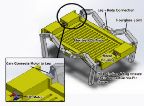
The leg design and the designs of different joint types that are presented in this work are for a miniature soft/hybrid robot, shown in Fig. 1. The miniature robot design is modified from another work conducted in our lab, MinIAQ– II, a miniature foldable quadruped with individually actuated legs [15]. In this, soft/hybrid robot version, the kinematic design of the robot is kept, however the limitations on further miniaturization of the robot is eliminated by replacing the origami-inspired folding techniques used on acetate sheets with molding of soft materials to achieve a very similar mechanism design. Another advantage of utilizing the soft materials is the possibility of changing the shape or the size of the robot during operation using additional actuators to make the robot squeeze through small openings, if needed.
Fig. 1. CAD drawing of the soft/hybrid robot assembly with 3D printed thermoplastic polyurethane (TPU) body and hourglass type polydimethyl-siloxane (PDMS) legs.
The robot design consists of two main components; the body and the legs. The body has a rectangular form with a total of four DC motor housings, two of them located at the front and the rest located at the back, whereas the middle section is reserved for the circuit board. Symmetric extensions from the right and left sides of the body’s middle axis connect the legs to the body. Two different structural materials are used for the production of the body and the legs; thermoplastic polyurethane (TPU), which is a 3D printable soft material, is used for the body and the legs are made out of PDMS using molding methods. Further details on production of these modules are presented at section III. A. The Body and The Electronic Components
The actuators we use in this robot are selected as DC motors so that the design will stay simple and compact, and
the robot can be untethered. Very small DC motors with plastic planetary gearboxes of 1:700 ratio (Pololu, 1:700 Sub-Micro Plastic Planetary Gearmotor) are selected to run the robot’s leg mechanisms. The motors chosen have relatively high-torque output in comparison to actuators that we use to run similar mechanisms in foldable miniature robots, mainly because the soft materials we used in the mechanism are much dense and accordingly heavy in comparison to light foldable materials such as PET sheets or cardboards. The motors are connected to infinite turn potentiometers (used as absolute rotary encoders) by 3D printed miniature cams. The data gathered from the sensors are utilized through closed loop controllers in order to constantly regulate position and speed of the legs.
Motor housings have bridging roofs which provide a complete enclosure of the motor. Dimensions are decided such that a slim fit connection between the motors and the body is achieved. At the endpoint of the motors, small openings are made for motor cable connections to the circuit board.
Middle of the body is covered with walls that are taller than the circuit board and the circuit elements in order to provide partial protection from surroundings. The top of the robot body is not covered for easy circuit or component removal. A linear pattern of lines constitutes the body’s main frame, with gaps between them. This is done in order to reduce the weight of the robot while preserving its structural integrity. Even though currently the body of the robot is made from 3D printed soft material, we are working on making the whole robot using molding techniques from PDMS. B. Hourglass and Composite Leg Designs
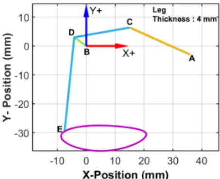
The leg mechanism we designed is a basic crank-rocker type fourbar linkage, with tip of the leg being an extension of the coupler link. The coupler curve is optimized by changing the link length ratios in order for the trajectory to resemble a D-shaped trajectory as much as possible. The flat side of this D shape is meant to be the downward half of the trajectory, which is the section where the leg touches the ground; and the curvy side is the part where the robot lifts its legs up into the air and steps forward. Normally, elliptic trajectories may also have been sufficient for walking motion. Nevertheless, as the flatness perishes from the section where the leg touches the ground, bumpier the motion becomes. This is a common issue for all miniature robots where the motion mechanism is chosen as a fourbar for simplicity. Unfortunately, there is no fourbar design with a partial straight-line in the downwards half of the coupler curve. (The closest is the lambda mechanism where the pseudo-straight line is in the upwards half of the coupler curve.) Therefore, the optimization comes as close to a D-shape as possible with a regular fourbar morphology. The resulting fourbar from this optimization is shown in Fig. 2.
The main challenge going from conceptual design phase to detailed leg mechanism design is to ensure that the resulting legs will follow the projected trajectory from the conceptual design phase. The mechanism design and the corresponding
Fig. 2. Conceptual leg mechanism and the trajectory of the foot. The motor position is assumed to be the origin. BD = 5.13 mm, CD = 19.49 mm, AC = 22.96 mm, DE = 32.76 mm, Constant Angle CDE = 105.84◦
trajectory is valid for perfectly rigid links and pin joints, which enable 360 degrees of rotation. However, we use soft materials for fabrication, meaning that the links will not be perfectly rigid. This forces us to come up with a joint design, in which the links are not perfectly rigid, but still as the mechanism is actuated from a cam, the rotational displacements in the mechanism occur at or close to the prescribed joint locations. We propose two different completely soft solutions to this problem.
Our initial design proposal, which we refer to as the ’Hourglass’ version, is named after it’s joints’ resemblance to hourglasses, as shown in Fig. 3. The leg mechanism is composed of the same material (PDMS) all along but its geometric properties are variant among different sections. The design is such that the joint locations are like thin features of an hourglass whereas links are much thicker. So that, the mechanism tends to deform from the joint locations due to the difference of mechanical compliance at the links and the joint locations. The rotational input given to the crank of the mechanism provides bending at these ’hourglass’ locations such that in the end, a very similar trajectory to the calculated trajectory is observed.
Fig. 3. CAD drawing of the hourglass leg. (Blue markers: joints, green marker: body connection, red markers: pin locations.)
Despite functioning properly, the hourglass joints tend to tear easily during fabrication process, which lead us to believe that the mechanical stress on the joints during the operation might also easily break the joints. In order to solve the fabrication issues and potential joint weakness another design is proposed. In this other design the links have the same dimensions and they are made of PDMS, the
same structural material that is used in the hourglass design. However, the structure thickness stays the same for both the links and the joints in this version. Instead, we differenti-ated the materials used for the link and joint locations, as shown in Fig. 4. Joints were made up from a much softer version of the material we used for the links (commercially known as EcoFlexTM) in order to make them significantly
more compliant in comparison to the links. When actuated, the trajectory observed showed strong resemblance to the calculated trajectory.
Fig. 4. CAD drawing of the composite leg. (Blue markers: joints, green marker: body connection, red markers: pin locations.)
III. FABRICATION
Fabrication can be seen as the biggest challenge to be tackled in case of our robot, especially because the curing of different elastomers to create a working mechanism as we describe here has not been reported in literature. We have two main methods of fabrication which are 3D Printing of flexible filaments and molding of polymers into 3D Printed hard plastic molds. For all 3D Printing purposes; we use a Prusa MK2S FDM (Fused Deposition Modeling) Printer.
Printing of flexible filaments is a challenge, especially with complex geometries like our robot’s body. This is due to the problematic retraction properties of the flexible filaments. Most of the 3D Printing applications worldwide are done by usage of hard plastic filaments; PLA (Polylactic Acid) and ABS (Acrylonitrile Butadiene Styrene). FDM printers retract the filament that is being deposited through the nozzle during travel in order to prevent phenomena such as webbing, stringing, and over extrusion. Hard plastic filaments like PLA and ABS are easily retracted, whereas flexible ones tend to buckle up during this process as they can easily find a less resistant path among the way up. To overcome this, we specifically set up the speed of the printer nozzle for all print moves to 15mm/s, much slower than the default value. We also reduced retraction and modified the printer head to increase the tension on the filament. Printing temperature was kept at 195◦C. Talc powder was applied on the printing bed prior to the print for easy removal after the process is done. The same printer was also used for the fabrication of PLA molds.
Fabrication of the legs from elastomers are done using molding techniques, which is often classified under soft lithography methods [16]. PDMS Sylgard® 184
manufac-tured by Dow Corning was used to form the PDMS network. The kit consists of two components: pre-polymer (base) and cross-linker (curing agent). As a general procedure; the two
components were mixed in a plastic beaker and degassed by keeping the mixture under vacuum for 15 min. The degassed mixture was poured into the PLA molds produced by 3D printing. The manufacturer recommends to mix the base and curing agent with the 10:1 weight ratio. However, studies showed that the mechanical properties such as stiffness of the final PDMS material depend on the mixing ratio of the components [17], [18]. Thus, increasing the amount of the cross-linker led to the stiffening of the PDMS network, e.g. elastic modulus of PDMS cured with ratio 5:1, 7:1, 10:1 (base / curing agent) was found to be equal to 3.59, 2.91, 2.61 MPa, respectively [18]. In our case, the PDMS network of hourglass leg should characterize with a higher stiffness in order to hold the body, but in the same time it should be elastic enough to bend at the joint locations. Thus, three mixing ratios of 5:1, 7:1, and 10:1 were examined for achieving the desired optimum stiffness. Our preliminary data showed that components mixed with ratio 10:1 turned out to be too soft to hold the body. However, promising results were obtained for the legs made of PDMS cured with 5:1 and 7:1 ratios. Due to the difficulties during the release of PDMS leg (ratio 5:1) out of the PLA mold, PDMS cured with 7:1 weight ratio was used to fabricate the hourglass legs. Still, releasing the leg from the mold was conducted slowly, because hourglass shaped joints were vulnerable.
Part A and B of EcoFlexTM 00-30 (Smooth-On), which
is used in the making of the composite leg was mixed 1:1 in a plastic beaker and degassed at vacuum after mixing. To enhance visualization of the EcoFlexTM parts, Silc Pilg Red
(Smooth-On) dye was used. The following processes were used for the fabrication of the two different leg designs: A. Hourglass Leg
PDMS Sylgard® 184 was mixed in a 7:1 ratio of a
pre-polymer and cross-linker and mixed very well in a plastic cup. After that, in order to get rid of the air bubbles, the mixture was placed in a vacuum oven. Using syringe the PDMS was poured into the PLA mold and placed in the oven at 70◦C for one hour (Fig. 5a). Then, the mold was kept at room temperature for 18 hours to finish the curing process (Fig. 5b).
Fig. 5. Fabrication process for the hourglass leg
B. Composite Leg
Using a syringe, the PDMS mixture, prepared the same way as described in section III-A, was poured into the PLA mold and placed in the oven at 70◦C for one hour.
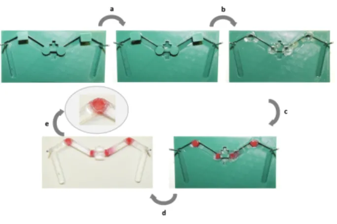
To be able to pour EcoFlexTMinto the mold, we designed
puzzle blocks in the joint locations (Fig. 6a, b). These blocks prevented PDMS from leaking to joint locations and
Fig. 6. Fabrication process for the composite leg
were removed from the mold after the curing process was completed (Fig. 6c).
After PDMS was cured for an hour, the puzzle blocks were removed and EcoFlexTM 00-30 (previously mixed in a 1:1
weight ratio of part A and part B, and Silc Pig Red, manu-factured by Smooth-On) was poured into the joint locations. The mold was kept at room temperature for 18 hours to let the curing process finish. Fig. 6e suggests that EcoFlexTM
did not considerably diffuse into the PDMS matrix during curing and both PDMS and EcoFlexTM remained as joined
but separate material domains.
IV. SIMULATION ANDEXPERIMENTS
Once the hourglass and composite leg mechanisms are fabricated, they are assembled with the 3D printed TPU robot body and connected to the motors via the 3D printed cams for experiments. We want to achieve a trajectory similar to the one acquired at the conceptual design phase, however we also would like to know which leg design is preferable. Since the failure of such a mechanism is expected to occur at the joint locations, we would like to know which joint design would have lower mechanical stress during a similar deformation. Higher mechanical stress at the joint locations might lead to instant failure due to high loads as well as earlier failure from fatigue.
In order to find the stress levels experienced in the two designs, a finite element model of the two joints are built in Comsol environment. To show that the legs follow an acceptable walking trajectory, experiments are run with both designs and the foot trajectory is tracked. The two designs are also run for 250.000 cycles to see if the mechanisms would undergo fatigue failure or the composite mechanism would delaminate from the locations where two different materials are combined.
A. Finite Element Simulations
In order to see the amount of stress generation at the joint locations, we decided to utilize Finite Element Analysis (FEA) to compare the two types of joints. Two mechanisms are designed for the FEA runs: in one design, two PDMS links are connected with an hourglass PDMS joint, in the
other, two PDMS links are connected with the same thick-ness EcoFlexTM joint. For the designs, we tried to keep the rotational stiffness of the joints the same, i.e. the two designs would bend the same amount under the same applied moment. Following, we imported these to the COMSOL Multiphysics medium. We used the solid mechanics toolbox to conduct a time dependent study. A total distributed force of 0.001 Newtons was applied for 10 seconds at the rigid link above the joint location. Extremely Fine physics-controlled mesh was used for both cases. All other boundaries are set to be free except for the base, which is fixed.
(a) (b)
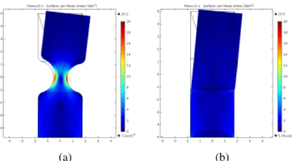
Fig. 7. (a) COMSOL®simulation for the hourglass design. (b) COMSOL®
simulation for the composite design.
Figure 7(a) shows the FEA results for the hourglass type joint and the Fig. 7(b) shows the results for the composite type mechanism. Hourglass mechanism has an average stress of 8.008 Pa along the horizontal centerline of the geometry whereas the composite design undergoes an average stress of 1.977 Pa at the same line. Furthermore, the maximum stress values are 20.262 Pa for the hourglass design and 7.323 Pa for the composite design accordingly. Both the average and maximum stress values are found by taking the average of all instants for 10 seconds. Results show that even though the composite version has stress singularity locations such as material interfaces and corners, the magnitude of stress at these locations are still lower than the hourglass version. This result is not surprising considering the width difference. However, combining the results with the results from trajectory experiments and cyclic runs suggest that a possible failure of the leg is much likely to happen with the hourglass version, since delamination of ecoflex and PDMS parts also does not happen. Fear of such delamination often leads researchers to use hourglass type structures rather than the composite type.
B. Trajectory Experiments
To observe the trajectories of the two leg designs, we attached the legs to a TPU, 3D printed body, connected the motors to the legs and actuated the mechanisms. During these experiments, side view video of the legs are recorded and the position of the feet are tracked using simple image processing techniques. A total of ten cycles are done with each leg specimen and approximately ten points are taken by image processing for each cycle. All of the acquired points from the experiments are shown in Fig. 9. A screenshot from these experiments is shown in Fig. 8.
Fig. 8. A single frame from the side view video recording of the composite leg trajectory experiments.
The experimental process we used is straightforward. Initially, tips of the legs were colored blue. Then, the linkage was driven and the motion of the leg was recorded in front of a green screen. Later, the video file was imported to MATLAB® environment. For the whole length of the video,
each frame was read separately. These separate readings were thereafter filtered through a basic if loop in order to only preserve pixels with significant blue values. Each filtered frame’s centroid was found and its coordinates were preserved in a matrix. After all frames were processed, these coordinates were plotted to visualize the according trajectory. This process was repeated for both of the legs proposed in this paper. In addition to the experimental results, the expected trajectory from the fourbar mechanism with the rigid links and ideal pin joints assumption is also shown in Fig. 9.
Fig. 9. The comparison of trajectories of the two different proposed mechanisms and the simulation results with the rigid link/ideal pin joint assumption. The data is acquired through image processing. The motor positions of the leg mechanisms are taken as the origin.
The experimental results show no considerable differ-ence between the two mechanisms. However, the hourglass mechanism seems to have a wider trajectory whereas the composite mechanism has a smoother trajectory. Both of the trajectories generated by the soft mechanisms are slightly larger than the simulated trajectory of the fourbar with same dimensions but rigid links and ideal pin joints. The difference between the simulated results and the experimental data can be attributed to the elasticity of the links. We can also visually observe that the links extend and contract slightly during operation.
C. Cyclic Runs
Another experiment we ran was driving each of the different leg mechanisms for three days continuously at 1
Hz drive frequency to see if they would undergo any fatigue failure. Such experiments correspond to about 250.000 cycles of operation. Other than the fatigue, we were also worried that the composite legs’ material changing interfaces might delaminate; as we thought that sudden (virtually discontin-uous) change in the material and accordingly the Young’s Modulus would be problematic. Therefore, a test setup was constituted with utilization of a camera and a power supply. The motors driving the leg mechanisms were powered con-tinuously while the camera captured snapshots of the legs every ten minutes. Results show that neither one of the legs would fail from fatigue nor would we able to observe any crack formations. Hence, we concluded that both of the joint designs can be utilized in a soft robot for long term operation. D. Discussion
From our experimental trajectory and cyclic run analysis, we found no significant difference between the two mech-anisms, except the trajectory generated by the composite design being slightly smoother. On the other hand, it is easier to fabricate the composite mechanism because the hourglass joints tend to break during molding. In addition, the FEA results suggest that the mechanical stress the hourglass design experiences is much higher than the stress the composite design experiences. Therefore, we believe the composite design is mechanically superior to the hourglass design for soft/hybrid robots.
V. CONCLUSION ANDFUTUREWORKS
In this work, we presented two new soft leg mechanisms that can be actuated using DC motors. Both of the mech-anisms utilize elastomers, so their links are not perfectly rigid. The joints are defined with geometric differences in the hourglass design and with the utilization of different materials in the composite design. To be able to make the composite design, we came up with a new fabrication method that involves 3D printed molds with removable parts and a two step molding process. After fabrication, the two designs are evaluated for the trajectories they generate and the mechanical stress they experience. We found that they can both generate acceptable trajectories however the mechanical stress that the hourglass design experiences is significantly higher than the composite design, which would mean that the hourglass design is more prone to failure. We also experienced this during fabrication; the hourglass legs tend to break from their joint locations when the legs are being removed from the molds.
Currently, we are working on the complete robot design and electronics integration. We are also focused on designing the constriction mechanism for the legs and the body so that the robot can squeeze through an opening smaller than its cross-section. The body will also be made from PDMS or a similar elastomer for the future design. At the end, we envision an untethered soft/hybrid robot made out of elastomers and a few hard components such as DC motors and electronic components, that can change the shape of its body or motion generation mechanism.
ACKNOWLEDGMENTS
The authors would like to thank members of Bilkent Miniature Robotics Laboratory for their invaluable assistance throughout this project. This work is funded by the Scientific and Technological Research Council of Turkey (T ¨UB˙ITAK) grant no. 216M195.
REFERENCES
[1] C. Laschi, M. Cianchetti, B. Mazzolai, L. Margheri, M. Follador, and P. Dario, “Soft robot arm inspired by the octopus,” Advanced Robotics, vol. 26, no. 7, pp. 709–727, 2012.
[2] H.-T. Lin, G. G. Leisk, and B. Trimmer, “Goqbot: a caterpillar-inspired soft-bodied rolling robot,” Bioinspiration & biomimetics, vol. 6, no. 2, p. 026007, 2011.
[3] N. W. Bartlett, M. T. Tolley, J. T. Overvelde, J. C. Weaver, B. Mosadegh, K. Bertoldi, G. M. Whitesides, and R. J. Wood, “A 3d-printed, functionally graded soft robot powered by combustion,” Science, vol. 349, no. 6244, pp. 161–165, 2015.
[4] M. T. Tolley, R. F. Shepherd, B. Mosadegh, K. C. Galloway, M. Wehner, M. Karpelson, R. J. Wood, and G. M. Whitesides, “A resilient, untethered soft robot,” Soft robotics, vol. 1, no. 3, pp. 213– 223, 2014.
[5] B. Baytekin, S. D. Cezan, H. T. Baytekin, and B. A. Grzybowski, “Ar-tificial heliotropism and nyctinasty based on optomechanical feedback and no electronics,” Soft robotics, vol. 5, no. 1, pp. 93–98, 2018. [6] S.-H. Kim, S. Oh, K. B. Kim, Y. Jung, H. Lim, and K.-J. Cho, “Design
of a bioinspired robotic hand: Magnetic synapse sensor integration for a robust remote tactile sensing,” IEEE Robotics and Automation Letters, vol. 3, no. 4, pp. 3545–3552, 2018.
[7] T. Umedachi and B. A. Trimmer, “Design of a 3d-printed soft robot with posture and steering control,” in Robotics and Automation (ICRA), 2014 IEEE International Conference on. IEEE, 2014, pp. 2874–2879. [8] A. Menciassi, S. Gorini, G. Pernorio, L. Weiting, F. Valvo, and P. Dario, “Design, fabrication and performances of a biomimetic robotic earthworm,” in Robotics and Biomimetics, 2004. ROBIO 2004. IEEE International Conference on. IEEE, 2004, pp. 274–278. [9] Y. Sugiyama and S. Hirai, “Crawling and jumping of deformable
soft robot,” in Intelligent Robots and Systems, 2004.(IROS 2004). Proceedings. 2004 IEEE/RSJ International Conference on, vol. 4. IEEE, 2004, pp. 3276–3281.
[10] C. D. Onal and D. Rus, “Autonomous undulatory serpentine locomo-tion utilizing body dynamics of a fluidic soft robot,” Bioinspiralocomo-tion & biomimetics, vol. 8, no. 2, p. 026003, 2013.
[11] Y. S. Song, Y. Sun, R. Van Den Brand, J. Von Zitzewitz, S. Micera, G. Courtine, and J. Paik, “Soft robot for gait rehabilitation of spinalized rodents,” in Intelligent Robots and Systems (IROS), 2013 IEEE/RSJ International Conference on. Ieee, 2013, pp. 971–976. [12] J. T. Muth, D. M. Vogt, R. L. Truby, Y. Meng¨uc¸, D. B. Kolesky, R. J.
Wood, and J. A. Lewis, “Embedded 3d printing of strain sensors within highly stretchable elastomers,” Advanced Materials, vol. 26, no. 36, pp. 6307–6312, 2014.
[13] Y. Meng¨uc¸, Y.-L. Park, H. Pei, D. Vogt, P. M. Aubin, E. Winchell, L. Fluke, L. Stirling, R. J. Wood, and C. J. Walsh, “Wearable soft sensing suit for human gait measurement,” The International Journal of Robotics Research, vol. 33, no. 14, pp. 1748–1764, 2014. [14] M. Wehner, R. L. Truby, D. J. Fitzgerald, B. Mosadegh, G. M.
Whitesides, J. A. Lewis, and R. J. Wood, “An integrated design and fabrication strategy for entirely soft, autonomous robots,” Nature, vol. 536, no. 7617, p. 451, 2016.
[15] M. Askari, C. Karakadıo˘glu, F. Ayhan, and O. ¨Ozcan, “MinIAQ-II: A miniature foldable quadruped with an improved leg mechanism,” in 2017 IEEE International Conference on Robotics and Biomimetics (ROBIO). IEEE, 2017.
[16] Y. Xia and G. M. Whitesides, “Soft lithography,” Angewandte Chemie International Edition, vol. 37, no. 5, pp. 550–575, 1998.
[17] H. Michelle´a Grandin et al., “Micro-well arrays for 3d shape control and high resolution analysis of single cells,” Lab on a Chip, vol. 7, no. 8, pp. 1074–1077, 2007.
[18] Z. Wang, A. A. Volinsky, and N. D. Gallant, “Crosslinking effect on polydimethylsiloxane elastic modulus measured by custom-built compression instrument,” Journal of Applied Polymer Science, vol. 131, no. 22, 2014.