Special Issue on Metamaterials LHM
Experimental investigation of reflection
characteristics of left-handed metamaterials
in free space
K. Aydin and E. Ozbay
Abstract: The transmission and reflection characteristics are presented of a one-dimensional (1D) left-handed metamaterial (LHM) and its constituents, split ring resonator and thin wire arrays. A well-defined left-handed transmission band with a peak value of 27.2 dB is obtained at frequencies where effective permittivity and permeability are both negative. A sharp dip (234.5 dB) at the reflection spectrum of 1D ordered LHM is observed. The frequency of ultra-low reflection did not change considerably for another LHM with a different thickness, meaning that the low reflection is not because of the thickness resonance but rather the impedance-matching of LHM at the surface. Disorder in LHM structures is shown to affect the reflection characteristics.
1 Introduction
Left-handed metamaterials (LHMs) have become a remarkable research area in recent years and have received a considerable amount of interest due to their exotic electro-magnetic (EM) properties. Veselago, in his pioneering theoretical work, pointed out that a material exhibiting negative values of dielectric permittivity (1) and magnetic permeability (m) would subsequently have a negative index of refraction [1]. The name left-handed material is used because the electric, magnetic and wavevector com-ponents all form an LH coordinate system in such media. Generally, 1 and m are both positive for ordinary materials. However, by taking advantage of artificially constructed periodic structures, one can have negative values of 1 and m. Periodically arranged thin metallic wires are used as negative effective permittivity (1eff) media, since dielectric
permittivity is less than zero below plasma frequency[2, 3]. An array of split ring resonators (SRRs) is shown to exhibit a negative effective permeability (meff) for frequencies close
to the magnetic resonance frequency (vm) of the SRR
structures [4]. The first experimental realisation of LHMs was achieved by arranging periodic SRRs (i.e. m(v) , 0 media) with the thin wire arrays (i.e. 1(v) , 0 media) [5, 6]. Experimental verification of negative refraction was reported shortly after supporting the existence of neff, 0 medium[7 – 10]. Then, different designs and
con-figurations of LHMs were reported, in which their trans-mission properties were studied in detail[11 – 14].
One of the rich physical properties of LHMs is the perfect lens behaviour. Provided that the impedance is matched, LHMs can restore the amplitude of evanescent waves
and therefore enable subwavelength focusing [15]. Subwavelength resolution was experimentally verified for negative index materials made of photonic crystals (PCs) [16]and LH transmission-line lenses[17]. In recent work, it has been experimentally shown that it is also possible to overcome the diffraction limit and therefore obtain flat-lens focusing with conventional LHMs utilising a common approach of SRR-wire geometry [18]. The structure is shown to exhibit a narrow frequency region with a very low reflection; the impedance is therefore matched at the air-LHM interface[19].
In this paper, we investigate the transmission and reflec-tion characteristics of ordered and disordered LHMs. The emphasis should be placed on reflection properties since the transmission characteristics are studied in detail both theoretically and experimentally, but the reflection properties are quite unexplored. In addition to the studies on the reflection spectra of SRR-only and wire-only media [11, 13], there is also experimental evidence of impedance-matched metamaterial[19]. In this paper, we aim to study LHMs that exhibit very low reflection, or impedance-matched materials and their constituents in detail. First, we present the transmission and reflection spectra of SRR-only and wire-only media to provide a clear understanding of how our particular designs respond to EM waves. Then, the reflection spectra of LHM should be provided. There is a narrow frequency region with very low reflection within the LH transmission band. We have shown that the observed behaviour is not because of the thickness resonance since the impedance-matched frequency range did not change considerably. We have finally investigated how the reflection characteristics change when a disorder is introduced into the LHM structure.
2 Experimental procedure
In this section, the experimental procedure will be explained in detail. First, the design and parameters of the structures that were used in the experiments will be provided. Then, the experimental setup for measuring the transmission and reflection spectra will be explained in detail.
#The Institution of Engineering and Technology 2007 doi:10.1049/iet-map:20050301
Paper first received 29th November 2005 and in revised form 15th June 2006 The authors are with the Nanotechnology Research Center, Bilkent University, Bilkent, Ankara 06800, Turkey and Department of Physics, Bilkent University, Bilkent, Ankara 06800, Turkey
E. Ozbay is also with the Department of Electrical and Electronics Engineering, Bilkent University, Bilkent, Ankara 06800, Turkey
2.1 Structures
LHMs are usually fabricated as periodic structures of alter-nating layers of SRRs and wires. Here, we follow this common design for obtaining a LHM structure. Metallic patterns are printed on FR4 dielectric printed circuit boards (PCBs).Fig. 1 shows a schematic drawing of SRR unit cell. The dark patterns belong to metal and the lighter patterns belong to dielectric board. The metal used for depo-sition is copper and has a thickness of 30 mm. The thickness of the dielectric board is t ¼ 1.56 mm. The dielectric board has dielectric constant of 1 ¼ 3.85. The radii of the inner and outer rings as depicted in Fig. 1 are r1¼ 1.6 mm,
r2¼ 2.5 mm, r3¼ 2.7 mm and r4¼ 3.6 mm. The width of
the splits are d ¼ 0.2 mm.
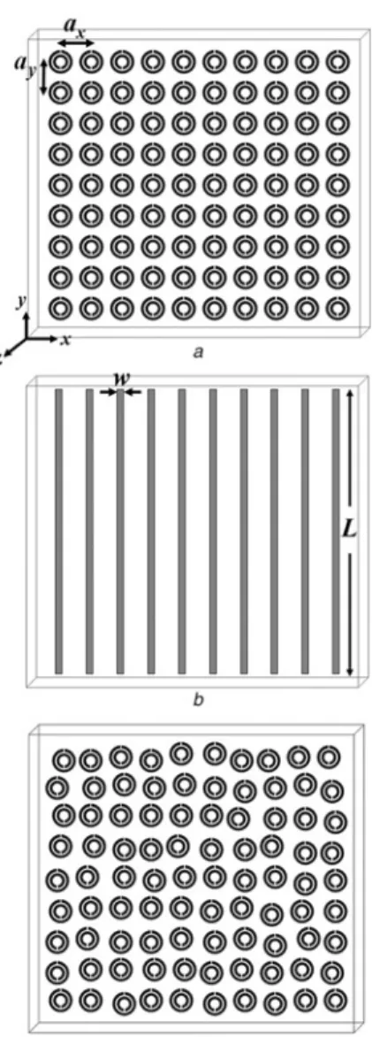
The periodicity in the two directions (x and y) is achieved by printing 2D-arrays of SRR patterns on planar dielectric boards as depicted in Fig. 2a. The periodicity in the x- and y-directions are equal and ax¼ ay¼ 8.8 mm. The
periodicity in the z-direction is achieved by stacking a large number of such patterned planar substrates. The planar SRR boards are stacked with a lattice constant of az¼ 6.5 mm. Notice that there is a 4.94-mm air region
between the neighbouring SRR boards. The number of unit cells along the x, y and z directions are Nx¼ 10,
Ny¼ 20 and Nz¼ 25.
Similarly, a thin wire array is fabricated as shown in Fig. 2b. The length and width of the continuous thin wire structures are L ¼ 19 cm, and w ¼ 0.9 mm, respectively. The number of unit cells and periodicities along the x- and z-directions are same with that of SRR arrays. Since the wire structure is continuous along the y-direction, there is no such periodicity in this direction.
The LHM structure is obtained by patterning SRR array (Fig. 2a) on the front side of the PCB board and the wire array (Fig. 2b) on the back side of the PCB board. The structure is a one-dimensional (1D) LHM structure and composed of Nx¼ 10, Ny¼ 20, and Nz¼ 25 unit cells,
with lattice spacings ax¼ ay¼ 8.8 mm and az¼ 6.5 mm.
In this paper, we have also investigated the effect of disorder on the reflection characteristics of LHM. For this purpose, we have introduced disorder into the LHM system, by destroying the periodicity of SRR array along x- and y-directions, randomly (Fig. 2c). The disorder is introduced as follows: each SRR on the board with lattice point, ~rn, where ~r ¼ x^i þ y^j, is displaced with
~rn+ ~dr. Here ~dr is the randomness parameter and we
choose it as j~drj ¼a/9, where a ¼ ax¼ ay¼ 8.8 mm is
the lattice constant on periodic SRR board. Then, the disordered LHM structure is obtained by arranging disordered SRR arrays (Fig. 2c) with the ordered wire arrays (Fig. 2b) with the same number of unit cells along all directions.
2.2 Experimental setup
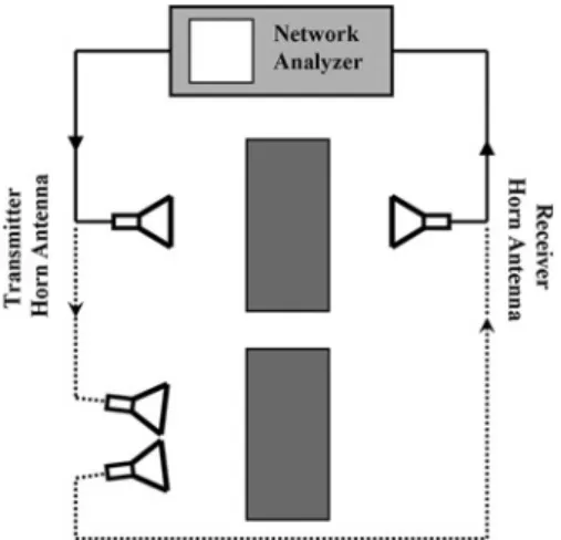
Transmission and reflection measurements are performed in free space rather than a waveguide environment. The experi-mental measurement setup consists of a HP 8510C network analyser and standard high-gain microwave horn antennas. The incident EM wave propagates along the x-direction, whereas E is along the y-direction and H is along the z-direction (seeFig. 2afor the directions). Transmitter and receiver horn antennas with aperture sizes of 6.5 cm, are connected to the HP-8510C network analyser as shown in Fig. 3. Solid line inFig. 3depicts the setup for transmission measurements. The transmission spectrum in free space is measured and set as calibration data for the network analyser. Then, the structure is inserted between the horn antennas, in which the transmission measurements are performed. The distance between the horn antennas is maintained at 35 cm.
For the reflection measurements, two horn antennas were placed close to each other by keeping the angle between the antennas very small. This setup is given by the dashed lines inFig. 3. The transmitter horn antenna sends the EM wave to the first surface of the structures and the receiver antenna measures the amplitude of the reflected EM waves. For calibration purposes, we placed a thick slab of metal (since Fig. 1 Schematic drawing of the unit cell of SRR structure on a
dielectric board of thickness t
Fig. 2 Schematic drawings of single layer of boards with SRRs and wire structures
a Ordered SRRs
b Ordered thin wire structures c Disordered SRRs
metals reflect all of the incident EM waves) 12 cm away from the antennas. Then, the structures are placed at the same dis-tance away from the antennas and reflection data are taken.
3 Results and discussion
3.1 Transmission and reflection properties of SRRs and wire structures
An SRR is a strongly resonant structure and even a single unit cell of SRR has a magnetic response to the incident EM field [20, 21]. The resonance is due to the splits which imitate magnetic poles[4]. Arranging SRR structures periodically in all directions increases the coupling between the SRRs; a wider band gap in the transmission spectrum is therefore observed compared to the measured frequency response (transmission coefficient) of single SRR [22]. Fig. 4shows the measured transmission (dashed line) and reflection (solid line) spectra of periodic SRR structure. There is an EM band gap between the frequencies 3.55 and 4.05 GHz. This band gap is due to the magnetic reson-ance of SRR structures and therefore at this frequency range meffis negative [14]. The measured reflection at this band
gap is close to unity so that SRR structures almost perfectly reflect the EM waves at the meff, 0 region.
The periodic arrangement of thin wire structures is previously shown to have plasma frequencies at microwave frequencies[2, 3]. The measured transmission (dashed) and reflection (solid) of periodic thin wire structures between 3.0 and 5.0 GHz are shown in Fig. 5. Throughout this frequency range, the wire structure does not transmit EM waves, and it nearly reflects the entire incident EM wave. The average reflection is around 22.5 dB at this frequency range. Therefore, the periodic wire structure behaves like a
low-pass filter and at this frequency range and down to zero frequency, 1effis negative[14].
3.2 Transmission and reflection properties of ordered LHMs
Fig. 6shows the measured transmission (dashed line) and reflection (solid line) spectra of a 1D LHM between 3.0 and 5.0 GHz. The periodic SRR structure is responsible for the negative permeability at the frequency range of 3.55 – 4.05 GHz. The periodic wire medium has negative effective dielectric permittivity covering this frequency region. The condition for the formation of LH transmission band is that the effective 1 and m should both be negative simultaneously. A transmission band is observed between 3.60 and 4.00 GHz, where the effective parameters of the LHM (i.e. 1effand meff) are both negative. The transmission
peak is measured to be 27.2 dB at 3.83 GHz.
The reflection spectrum of 1D LHM is provided with the solid line inFig. 6. At the frequency 3.77 GHz, a dip in the reflection spectrum is observed. The value of this dip is measured to be 234.5 dB. Therefore the EM waves inci-dent to the LHM structure around this specific frequency are nearly transmitted through the LHM without being reflected at the surface. This ultra-low reflection can be attributed to either matched impedance at the interface or to the thickness resonance of the slab. At this specific frequency, the impedance is matched to the free space. To check whether this resonance is due to thickness, we performed reflection measurements on an LHM sample with a different thickness along the propagation direction. The results are provided in the following section.
3.3 Effect of the number of layers on the reflection properties of LHMs
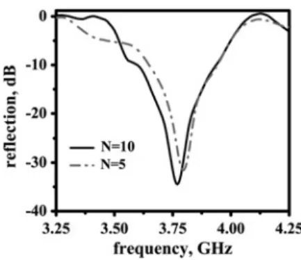
We have constructed another LHM structure with Nx¼ 5
layers along the propagation direction. Reflection spectra Fig. 3 Experimental setup for measuring transmission-amplitude
(solid) and reflection-amplitude (dashed) of the structures
Fig. 4 Measured transmission (dashed) and reflection (solid) spectra of ordered SRR structures
Fig. 5 Measured transmission (dashed) and reflection (solid) spectra of periodic thin wire structures
Fig. 6 Measured transmission (dashed) and reflection (solid) spectra of ordered LHM arranged by stacking layers of ordered SRRs and ordered wires consecutively
of two different numbers of layers are plotted inFig. 7. The solid line is the reflection spectrum of 10 layers, whereas the dash-dotted line corresponds to that of a 5-layered LHM structure. The dip at the reflection spectrum of LHM with five layers is measured to be at 3.79 GHz with a dip value of 231.2 dB. The frequency where the reflection dip is observed nearly did not change although the structure’s thickness is reduced by half. Therefore the impedance-matching cannot be due to the thickness resonance.
We can claim that this very low reflection from the surface LHM is due to the impedance-matching between air and LHM. The impedance of LHM will be equal to that of free space if the real parts of 1 and m are equal [15]. As seen inFig. 7, the impedance-matched frequency range (low-reflection regions) is narrow. It is not surprising to have such a small range for an impedance-matched frequency region, since meff of SRRs is known to vary
rapidly between the magnetic resonance (vmo) and
mag-netic plasma frequencies (vmp), although 1eff of wires
varies slowly throughout the frequency spectrum[4, 23].
3.4 Effect of the disorder on the reflection properties of LHMs
Recently, the studies concerning LHMs have been geared towards optical frequencies [24, 25]. The disorders that can occur during fabrication, or the stacking of these struc-tures, can affect the transmission and reflection properties of LHMs. The transmission characteristics of such disordered LHMs are investigated in detail, recently[22]. The effects of disorder need to be investigated for determining the restrictions imposed on the impedance-matching of LHMs. We aim to close this gap by studying the influence of introducing disorder on the reflection properties of 1D LHM.
Fig. 8 plots the reflection (solid line) and transmission (dashed line) characteristics of a disordered LHM structure. This structure was explained in detail in Section 2.1. As explained in the work of Aydin et al.[22], the transmission peak is reduced to 216.1 dB and the transmission band become narrower. We were unable to observe a narrow frequency region as in the case of ordered LHMs, where almost none of the incident waves is reflected. Instead, a wider reflection band is observed where the minimum value of the reflection is around 27 dB (Fig. 8). Therefore it is clear that the disorders influence both the reflection and transmission properties of LHM structures. Single SRR is a strongly resonant structure [22]. When several SRRs are arranged periodically, we obtain a frequency band with a negative permeability. Introducing disorders into the split ring array does not change the
band gap drastically [22]. However, when SRRs are combined together with the wire media to obtain an LH medium, disorders play an important role. They affect the coupling between the SRRs and wires, and therefore the resulting LHM structure’s characteristics are changed. Therefore the periodicity is important to achieve high trans-mission and low reflection from an LH material.
Careful designs and fabrications are needed in order to prevent such disadvantages of disorders, since disorder will be a more significant problem for submicron scale structures, which is required for operations in the near and far infrared. It is noteworthy that the disordered LHM struc-ture has the same thickness as the ordered one. This is another fact that the observed ultra-low reflection through an ordered LHM is indeed due to the impedance-matching, but not due to the thickness resonance of LHMs.
4 Conclusion
In conclusion, we have investigated the transmission and reflection characteristics of 1D SRRs, thin wires and LHM structures experimentally in free space. An LH trans-mission band is observed where both effective permittivity and effective permeability are simultaneously negative. We have observed a very sharp dip in the reflection spectrum. The reflection is very low at 3.77 GHz with a dip value of 234.5 dB, and therefore all of the incident EM waves can propagate inside the LHM structure. One may argue that this behaviour is indeed due to the thickness resonance of LHM structures. We have confirmed by using a different number of layers that the frequency of low reflection did not change considerably; hence, this characteristic cannot be attributed to thickness resonance. The influence of disorder on the reflection properties of LHMs was also investigated. The disorder was shown to influence the characteristics of LHMs by reducing the transmission and destroying the low reflection in the LH transmission band. The observed low reflection is due to the impedance-matching between the air and LHM interface. This is an important advance in metamaterial development, as when 1 and m are equal and both negative, we obtain a well-matched, negative index material. Impedance-matching at the surface of a metamaterial is desired, since it reduces the complications of the front-face reflections and assures that the negatively refracted beam is not the result of any experimental artifacts. Hence, much more energy will be transferred inside the LHM at the impedance-matched frequencies. Therefore the higher transmission (27.2 dB) can be explained by way of better impedance-matching between the free space and LHM for our particu-lar design.
Fig. 8 Measured transmission (dashed) and reflection (solid) spectra of disordered LHM arranged by stacking layers of disordered SRRs and ordered wires consecutively
Fig. 7 Measured reflection spectra of ordered LHMs with N ¼ 10 (solid), and N ¼ 5 (dash-dotted) number of layers along the propagation direction
5 Acknowledgments
This work is supported by the European Union under the projects EU-DALHM, EU NOE-METAMORPHOSE, EU NOE-PHOREMOST and TUBITAK under Project No. 104E090. One of the authors (E.O.) acknowledges partial support from the Turkish Academy of Sciences.
6 References
1 Veselago, V.G.: ‘The electrodynamics of substances with simultaneously negative values of permittivity and permeability’, Sov. Phys. Usp., 1968, 10, pp. 509 – 514
2 Pendry, J.B., Holden, A.J., Stewart, W.J., and Youngs, I.: ‘Extremely low frequency plasmons in metallic mesostructures’, Phys. Rev. Lett., 1996, 76, pp. 4773 – 4776
3 Pendry, J.B., Holden, A.J., Robbins, D.J., and Stewart, W.J.: ‘Low frequency plasmons in thin-wire structures’, J. Phys.: Condens. Matter, 1998, 10, pp. 4785 – 4809
4 Pendry, J.B., Holden, A.J., Robbins, D.J., and Stewart, W.J.: ‘Magnetism from conductors and enhanced nonlinear phenomena’, IEEE Trans. Microw. Theory Tech., 1999, 47, pp. 2075 – 2084 5 Smith, D.R., Padilla, W.J., Vier, D.C., Nemat-Nasser, S.C., and
Schultz, S.: ‘Composite medium with simultaneously negative permeability and permittivity’, Phys. Rev. Lett., 2000, 84, pp. 4184–4187 6 Shelby, R.A., Smith, D.R., Nemat-Nasser, S.C., and Schultz, S.: ‘Microwave transmission through a two-dimensional, isotropic, left-handed metamaterial’, Appl. Phys. Lett., 2001, 78, pp. 489 – 491 7 Shelby, R.A., Smith, D.R., and Schultz, S.: ‘Experimental verification
of a negative index of refraction’, Science, 2001, 292, pp. 77– 79 8 Parazzoli, C.G., Greegor, R.B., Li, K., Koltenbah, B.E., and Tanielian,
M.: ‘Experimental verification and simulation of negative index of refraction using Snell’s law’, Phys. Rev. Lett., 2003, 90, pp. 107401-1 – 107401-4
9 Houck, A.A., Brock, J.B., and Chuang, I.L.: ‘Experimental observations of a left-handed material that obeys Snell’s law’, Phys. Rev. Lett., 2003, 90, pp. 137401-1– 137401-4
10 Aydin, K., Guven, K., Soukoulis, C.M., and Ozbay, E.: ‘Observation of negative refraction and negative phase velocity in left-handed metamaterials’, Appl. Phys. Lett., 2005, 86, pp. 124102-1– 124102-3 11 Ziolkowski, R.W.: ‘Design, fabrication and testing of double negative metamaterials’, IEEE Trans. Antennas Propag., 2003, 51, pp. 1516– 1529
12 Bayindir, M., Aydin, K., Ozbay, E., Markos, P., and Soukoulis, C.M.: ‘Tranmission properties of composite metamaterials in free space’, Appl. Phys. Lett., 2002, 81, p. 120
13 Ozbay, E., Aydin, K., Cubukcu, E., and Bayindir, M.: ‘Transmission and reflection properties of composite double negative metamaterials in free space’, IEEE Trans. Antennas Propag., 2003, 51, pp. 2592 – 2595
14 Aydin, K., Guven, K., Kafesaki, M., Zhang, L., Soukoulis, C.M., and Ozbay, E.: ‘Experimental observation of true left-handed transmission peaks in metamaterials’, Opt. Lett., 2004, 29, pp. 2623 – 2625
15 Pendry, J.B.: ‘Negative refraction makes a perfect lens’, Phys. Rev. Lett., 2000, 85, pp. 3966– 3969
16 Cubukcu, E., Aydin, K., Foteinopolou, S., Soukoulis, C.M., and Ozbay, E.: ‘Subwavelength resolution in a two-dimensional photonic crystal based superlens’, Phys. Rev. Lett., 2003, 91, pp. 207401-1 – 207401-4
17 Grbic, A., and Eleftheriades, G.V.: ‘Overcoming the diffraction limit with a planar left-handed transmission-line lens’, Phys. Rev. Lett., 2004, 92, pp. 117403-1– 117403-4
18 Aydin, K., Bulu, I., and Ozbay, E.: ‘Focusing of electromagnetic waves by a left-handed metamaterial flat lens’, Opt. Express, 2005, 13, pp. 8753 – 8759
19 Aydin, K., and Ozbay, E.: ‘Negative refraction through an impedance matched left-handed metamaterial slab’, J. Opt. Soc. Am. B, 2006, 23, pp. 415 – 418
20 Gay-Balmaz, P., and Martin, O.J.F.: ‘Electromagnetic resonances in individual and coupled split-ring resonators’, J. Appl. Phys., 2002, 92, pp. 2929 – 2936
21 Aydin, K., Bulu, I., Guven, K., Kafesaki, M., Soukoulis, C.M., and Ozbay, E.: ‘Investigation of magnetic resonances for different split-ring resonator parameters and designs’, New J. Phys., 2005, 7, pp. 168-1 – 168-15
22 Aydin, K., Guven, K., Katsarakis, N., Soukoulis, C.M., and Ozbay, E.: ‘Effect of disorder on magnetic resonance band gap of split-ring resonator structures’, Opt. Express, 2004, 12, pp. 5896 – 5901 23 Koschny, T., Kafesaki, M., Economou, E.N., and Soukoulis, C.M.:
‘Effective medium theory of left-handed materials’, Phys. Rev. Lett., 2004, 93, pp. 107402-1– 107402-4
24 Yen, T.J., Padilla, W.J., Fang, N., Vier, D.C., Smith, D.R., Pendry, J.B., Basov, D.N., and Zhang, X.: ‘Terahertz magnetic response from artificial materials’, Science, 2004, 303, pp. 1494– 1496
25 Linden, S., Enkrich, C., Wegener, M., Zhou, J., Koschny, T., and Soukoulis, C.M.: ‘Magnetic response of materials at 100 THz’, Science, 2004, 306, pp. 1351– 1353