i
MODELLING
A RESISTIVE-REFLECTOR ANTENNABY THE COMPLEX SOURCE
-
DUAL SERIES APPROACH:THE 2-D CASE OF H-POLARIZATION
I
Ayhan Altintas, Alexander 1. Nosich’, Vladimir B. Yurchenko+Bilkent University, Ankara, 06533, Turkey * Inst. Radiophysics and Electronics, Academy of Sciences
UI. Proskury, 12, Kharkov. 310085, The Ukraine
*
Kharkov State Polytechnical University, Kharkov, The Ukraine INTRODUCTIONReflector antenna simulation is normally performed under an assumption of the perfect conductivity of reflector. Such antennas have been studied by using high-frequency asymptotic approaches like Physical Optics (in particular, Aperture Integration) [I], Geometrical Theory of Diffraction [2], ray tracing, etc., and numerical ones as Method of Moments (MOM) [3]. We have failed to find any published paper dealing with a resistive or impedance-surface reflector, and so we suppose that our analysis of resistive reflector beamforming can be of potential interest. Meanwhile, even for a perfectly conducting geometry, MOM results in prohibitively large CPU time, if a reflector is larger than 20 lambda. What is even more disappointing, MOM is known to be heavily inaccurate if a kind of resonance takes place [4]. Therefore, in our analysis we use the Method of Regularization
(MOR)
modified by us for solving the scattering from a curved resistive strip[5].
Besides, to simulate a clirective feed in equally accurate manner, we use the Complex Source Method (CSM) [SI. The latter is known as a very efficient way to account for the feed directivity without loosing a mathematical correctness. Worth noting also is the fact that here no problems occurring in ray-tracing analyses appear, for blending the real-space edge diffraction points with compex-space reflection points. Thus, the presented here analysis is a recent development of our previous works 17-91,ABOUT THE ANALYSIS METHOD
In the H-polarization case, the integral equation for the electric current J(r) induced on the surface of a zero-thickness resistive reflector with the resistivity R can be written as in
[lo],
p. 205:M
Here, we take the right-hand-part as the field of a complex point source, of the directivity factor
kh,
placed at the point r, That isE”7(r)=CH,(li(k(r-r,, rbp (2)
Further. instead of solving (1) by MOM directly, we convert it to the dual series equations [5,7-91, in terms of surface current angular coefficients Then, we extract the static part of the kernel, and also, the part corresponding to the circular shape of the reflector By using the set of eigenfunctions of this partial operator as expansion functions. we obtain finally a regularized matrix equation, i e , that of the Fredholm 2-nd kind
X = [ A ( O ) + A ( N ” P I + A l B , (3)
Here, the operator A ( s ~ J vanishes if the true shape of reflector is the circular one, A(”P) vanishes for the
perfectly conducting geometry, and all the elements of Ato) and A(”P) are obtained analytically, i e , no numerical integrations are needed In the practical computations, rt has been verified that the p-digit
accuracy is achieved by taking the matrix truncation number as N=(f+lRuka+(p-1)2, independently of the reflectot's angular width, where a is the curvature radius at reflector's edge.
SAMPLE NUMERICAL RESULTS
Below, we demonstrate the effect of a thin lossy resistive reflector on the far-field radiation pattern, the total radiation power, and the directivity. We emphasize that these basic effects are obtained here with a uniformly guaranteed accuracy of 0.1%, for the adopted mathematical model. All the mechanitms such as reflector's surface curvature effect, power loss and resonance phenomena. guided and leaky waves contributions, etc., are inherently and exactly contained in our solution.
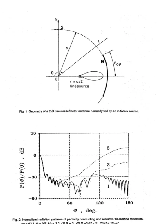
To simplify the computations, we took a circular reflector of the size D=7O/ambda and focal distance
F=0.5D
-
see Figure 1. Further, in order to simulate the frequency dependent character of resistivity. we postulated thatR=i(epsilon)-lntan [k(epsil~n)~~d] (4)
Computed and compared in Figure
2
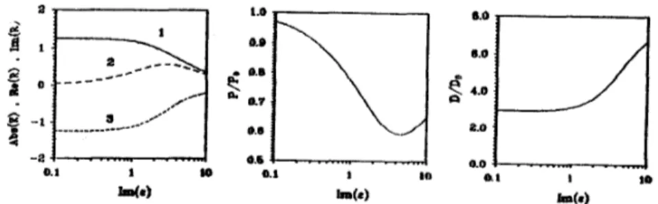
are the radiation patterns for the perfectly conducting reflector (zero resistivity), and for two values of the constant epsilon of the d=O.O1a thickness reflector (matched and unmatched reflector). The reflector edge illumination is -10 dB. One may see clearly that due to the resistivity, the reflector becomes partially transparent, and rear-zone sidelobes get higher, disturbing the radiation pattern significantly. If the reflector thickness is not matched, the drop in the directivity value can reach 100%. and the part of the source power is now lost for absorption-
see Figures 3 to 5. The way to match the reflector is to take its thickness approximately equal to an integer number of the half- wavelengths in reflector material. This value is the total reflection value for a plane wave incident normally to a flat-slab lossless resistive layer. The optimum thickness needed to maximize the coated antenna directivity is shifted from this value: the smaller the reflector radius, the greater the shift.REFERENCES
1.
E.
'J. Jull, Ape/fxe Anfznnas and Diffracfion Theory. London: Peter Peregrinus, 19812. V. A. Borovikov and E. E. Kinber, Geometrical Theory of Difraction , London: Peter Peregrinus, 1993. 3. J. J.
H.
Wang, Generalized Moment Mefhds in Electromagnetics, New York: John Wiley, 19914. G. L. Hower,
R.
G. Olsen, J. D. Earls and J. B. Schneider, "Inaccuracies in numerical calculation of scattering near natural frequencies of penetrable objects", /E€€ Trans. Antennas Propagat., vol. 41, pp.982-986, July 1993.
5. A. I. Nosich,
D.
Colak and A. Altintas, "H-wave scattering from a circularly curved impedance strip", Proc. Meditemnean Electrotechnical Conf. (MELECON-W), Antalya, pp. 446-448, 1994.6.
E.
V. Jull and G. A. Suedan. "Beam diffraction by planar and parabolic reflectors", E€€ Trans. Antennas Propagat., vol. 39, pp. 521-527. April 1991.7. T. Oguzer, A. 1. Nosich and A. Altintas, "Accurate simulation of reflector antennas by the complex source
-
dual series approach", Roc. Inf. Conf E/ecf"agnetics Aerospace Applications (ICEAA-93).Torino, pp. 335-338, 1993.
8. T. Oguzer, A. Altintas and A. 1. Nosich, "Analysis of radome covered circular reflectors by complex source
-
dual series approach", IEEEAntennas Fropagat. Symp. Digest, Seattle, pp. 70-73, 1993. 9. A. I. Nosich, A. Altintas, D. Colak and T. Oguzer, "Complex source-
dual series equations approach in modelling reflector antennas", Roc. lnt. Symp. Antennes (JINA-94), Nice!, pp. 485-488, 1994.10. T. B. A. Senior, "Some problems involving imperfect half planes", in
P.
L. E. Uslenghi (Ed.). Electmmagnetic Scattering, Orlando: Academic Press, 1978, pp. 185-219.'
Y
s
Fig.
1 Geometry of a 2-D circular-reflector antenna normally fedby
an in-focus sourceFig. 2 Normalized radiation pattems of perfectly conducting and resistive 10-lambda reflectors.
ka
= 62.8,
@-= W, kb= 3.5,
(1) R = 0,(2)
R-4.02
-
i2,
(3)R
=
f 0-
i7.M
kdFig. 3 Reflector's resistivity (a), total radiated power
(b),
and directivity (c) of antenna as functions of kd at epsilon = 3.45 + i0.25.Fig. 4 The same as a h e v e n u s the dielectric constant, ford = O.Ola,
Im
(epsilon) = 0.25.0.1 1 80
w.1
Fig.