BAŞKENT UNIVERSITY
INSTITUTE OF SCIENCE AND ENGINEERING
STRESS AND FATIGUE ANALYSIS OF ROAD WHEELS
MADE BY AL 2014-T6 FOR SELF-PROPELLED ARMY
PLATFORMS
S. ALPER KALE
MASTER'S THESIS 2019
STRESS AND FATIGUE ANALYSIS OF ROAD WHEELS
MADE BY AL 2014-T6 FOR SELF-PROPELLED ARMY
PLATFORMS
PALETLİ ASKERİ KARA ARAÇLARINDA ALÜMİNYUM
2014-T6 MALZEME KULLANILARAK YAPILMIŞ PORTÖR
TEKERİNİN GERİLME VE YORULMA ANALİZLERİNİN
YAPILMASI
S. ALPER KALE
Thesis submitted in partial fulfilment of the requirements for
the degree of Master of Science in Mechanical Engineering Department at Başkent University
This thesis, titled: “STRESS AND FATIGUE ANALYSIS OF ROAD WHEELS MADE BY AL 2014-T6 FOR SELF-PROPELLED ARMY PLATFORMS”, has been approved in partial fulfilment of the requirements for the degree of MASTER OF SCIENCE in MECHANICAL ENGINEERING DEPARTMENT, by our jury, on 29/01/2019.
Chairman (Advisor) : Prof. Dr. Faruk ELALDI
Member : Asst. Assoc. Dr. B. Cenk BALÇIK
Member : Assoc. Dr. Hakan Ahmet ARGEŞO
APPROVAL / 02 / 2019
BAŞKENT ÜNİVERSİTESİ FEN BİLİMLERİ ENSTİTÜSÜ YÜKSEK LİSANS TEZ ÇALIŞMASI ORİJİNALLİK RAPORU
Tarih: 01 / 02 / 2019 Öğrencinin Adı, Soyadı : Süleyman Alper KALE
Öğrencinin Numarası : 21720597 Anabilim Dalı : Makine Mühendisliği
Programı : Makine Mühendisliği Tezli Yüksek Lisans Programı Danışmanın Unvanı/Adı, Soyadı : Prof. Dr. Faruk ELALDI
Tez Başlığı : Paletli Askeri Kara Araçlarında Alüminyum 2014-T6 Malzeme Kullanılarak Yapılmış Portör Tekerinin Gerilme ve Yorulma Analizlerinin Yapılması
Yukarıda başlığı belirtilen Yüksek Lisans tez çalışmamın; Giriş, Ana Bölümler ve Sonuç Bölümünden oluşan, toplam 52 sayfalık kısmına ilişkin, 01 / 02 / 2019 tarihinde şahsım/tez danışmanım tarafından TURNITIN adlı intihal tespit programından aşağıda belirtilen filtrelemeler uygulanarak alınmış olan orijinallik raporuna göre, tezimin benzerlik oranı % 6’dır.
Uygulanan filtrelemeler: 1. Alıntılar hariç
2. Beş (5) kelimeden daha az örtüşme içeren metin kısımları hariç
“Başkent Üniversitesi Enstitüleri Tez Çalışması Orijinallik Raporu Alınması ve Kullanılması Usul ve Esaslarını” inceledim ve bu uygulama esaslarında belirtilen azami benzerlik oranlarına tez çalışmamın herhangi bir intihal içermediğini; aksinin tespit edileceği muhtemel durumda doğabilecek her türlü hukuki sorumluluğu kabul ettiğimi ve yukarıda vermiş olduğum bilgilerin doğru olduğunu beyan ederim.
Öğrenci İmzası:
Onay 01 / 02 / 2019
ACKNOWLEDGMENTS
I would first like to express my deepest gratitude to my supervisor Prof. Dr. Faruk ELALDI for his guidance, advice, criticism, encouragements, motivation, patience and insight throughout the research.
I would like to express my thanks to my dear father Ekrem KALE for his support and continuous faith in me.
I would like to thank my dear wife Didem KALE for her infinite support and patience. I would like to thank my friend Kerem ALTINDAŞ for his useful supports and comments.
Finally, I would also like to thank my family and friends who helped me a lot in finalizing this project within the limited time frame.
This research was carried out with the help of the Tank and Pallet Factory operated under 1st Central Maintenance Factory Management, located in Sakarya.
ABSTRACT
STRESS AND FATIGUE ANALYSIS OF ROAD WHEELS MADE BY AL 2014-T6 FOR SELF-PROPELLED ARMY PLATFORMS
S. Alper KALE
Başkent University, Institute of Science and Engineering Department of Mechanical Engineering
The road wheels are special support elements which are used between vehicle and tracking system in self-propelled howitzers and tanks. In this study, road wheels that are produced by aluminum alloy material used in T-155 Firtina Howitzer were numerically analyzed and experimentally tested by using pre-determined loads. For the fatigue analysis, the minimum static load per wheel was determined based on total weight of the vehicle and the maximum static load was determined from stress analysis. Fatigue tests were performed on the test specimens that were manufactured according to ASTM standard from the selected area on the road wheel. The internal structure of the fatigue test samples was observed by different NDT methods to determine any fatigue or fracture initiation. In this way, numerical stress and fatigue analysis of the aluminum road wheel and the real-time fatigue test were performed and the type of fatigue characteristic was examined. By performing all of these, it was aimed to determine the fatigue life of the existing configuration of road wheel model to be exposed to extremely high loading conditions and to show that aluminum alloy road wheels would be a good candidate to steel ones in the perspective of weight savings and required fatigue life.
KEYWORDS: self-propelled howitzer, aluminum road wheel, finite element method, stress analysis, fatigue analysis.
Advisor: Prof. Dr. Faruk ELALDI, Başkent University, Department of Mechanical Engineering
ÖZ
PALETLİ ASKERİ KARA ARAÇLARINDA ALÜMİNYUM 2014-T6 MALZEME KULLANILARAK YAPILMIŞ PORTÖR TEKERİNİN GERİLME VE YORULMA ANALİZLERİNİN YAPILMASI
S. Alper KALE
Başkent Üniversitesi Fen Bilimleri Enstitüsü Makine Mühendisliği Anabilim Dalı
Portör tekerleri kundağı motorlu obüsler ve tanklarda kullanılan palet ile araç arasında bulunan özel bir destek tekeridir. Bu çalışmada T-155 Fırtına Obüsünde kullanılan alüminyum alaşımlı malzeme ile üretilen portör tekerinin üzerine etki eden minimum statik yük aracın toplam ağırlığından ve maksimum statik yük ise yapılan sayısal gerilme analizi hesaplamasından bulunmuştur. Bulunan gerilme değerleri kullanılarak özel üretim yöntemiyle imal edilmiş alüminyum portör tekerinin malzeme olarak nasıl bir yorulma karakteristiği göstereceği sayısal ve deneysel olarak test edilmiştir. Portör tekeri üzerinde tespit edilen bölgeden alınan ve ASTM standardına göre üretimi yapılan test numuneleri üzerinde deneysel yorulma testleri yapılmıştır. Yorulma testi yapılmış numunelerin içyapısı incelenerek, herhangi bir yorulma veya çatlak başlangıcı olup, olmadığı gözlemlenmiştir. Böylece alüminyum malzemeden imal edilmiş portör tekerinin gerilme ve yorulma analizleri ile gerçek zamanlı yorulma testi deneyi yapılarak nasıl bir yorulma karakteristiği göstereceği ortaya çıkartılmıştır. Bu çalışmada, katı model geometrisi ve seçilen alüminyum alaşım malzemesinin plastik deformasyon özelliklerine bağlı olarak nihai konfigürasyona ulaştırılan bir modelin maruz kalacağı yük aralığında yorulma ömrünün tayin edilmesi ve alüminyum alaşımından yapılmış portör tekerleklerinin aynı yük koşullarında daha hafif ve yorulma direncine sahip aday portör tekerlekleri olduğunu gösterilmesi amaçlanmıştır.
ANAHTAR SÖZCÜKLER: kundağı motorlu obüsler, alüminyum portör tekeri, sonlu elemanlar yöntemi, stres analizi, yorulma analizi.
Danışman: Prof. Dr. Faruk ELALDI, Başkent Üniversitesi, Makine Mühendisliği Bölümü
TABLE OF CONTENTS
ABSTRACT ... i
ÖZ ... ii
TABLE OF CONTENTS ... iii
LIST OF FIGURES ... iv
LIST OF TABLES ... vi
LIST OF SYMBOLS AND ABBREVIATIONS ... vii
1. INTRODUCTION ... 1
1.1. Tracked Systems of Self-propelled Army Platforms ... 1
1.2. Road Wheels ... 2
1.3. Scope of the Thesis ... 3
1.4. Literature Survey about Road Wheels ... 5
2. NUMERICAL ANALYSIS ... 9
2.1 Finite Element Model and Mesh Structure ... 9
2.2 Fatigue Analysis ...17
2.3 Results of Finite Element Stress Analysis on Road Wheel ...21
2.4 Results of Finite Element Fatigue Analysis of Test Specimen ...26
3. EXPERIMENTAL ...28
3.1 Material Specifications ...28
3.2 Test Specimens and Test Setup...30
3.3 Testing ...34
3.4 Non-destructive Test Methods of Specimens ...36
3.4.1 Radiographic testing (RT) ...36
3.4.2 Liquid penetrant testing (PT) ...37
3.4.3 Eddy current testing ...38
3.4.4 Scanning electron microscope (SEM) ...39
3.4.5 Optical microscope ...42
4. RESULTS AND DISCUSSION ...45
4.1 Results obtained from Fatigue Prediction and Experimental Analysis ...45
4.2 Discussion and Comments ...48
5. CONCLUSION ...52
REFERENCES ...54
LIST OF APPENDIX ...57
LIST OF FIGURES
Figure 1.1 Road wheel of Firtina self-propelled howitzer ... 2
Figure 2.1 Computer aided drawing of road wheel ... 10
Figure 2.2 Computer aided drawing of test specimen ... 10
Figure 2.3 Mesh structure of road wheel ... 11
Figure 2.4 Mesh structure of test specimen ... 11
Figure 2.5 Central contact surface ... 12
Figure 2.6 Ground contact surface ... 13
Figure 2.7 Front side boundary conditions of road wheel ... 14
Figure 2.8 Back side boundary conditions of road wheel ... 14
Figure 2.9 S-N curve of hand forged aluminum alloy 2014 – T6 ... 16
Figure 2.10 Mechanical properties of hand forged aluminum 2014 – T6 on ANSYS workbench software ... 17
Figure 2.11 Typical S-N diagram of aluminum 2014 – T6 on ANSYS workbench software ... 17
Figure 2.12 Representation of S-N curve [18] ... 18
Figure 2.13 Mean stress effects [18] ... 19
Figure 2.14 Applied stress types of fatigue analysis [18] ... 19
Figure 2.15 Constant amplitude load ratio and mean stress correction theory ... 21
Figure 2.16 Equivalent stress (von-Mises) of aluminum road wheel ... 22
Figure 2.17 Total deformation of road wheel ... 24
Figure 2.18 Maximum principal elastic strain of road wheel ... 24
Figure 2.19 Stress region in radial loading ... 25
Figure 2.20 Distribution of radial stresses ... 25
Figure 2.21 Static analysis of test specimen at minimum loading ... 26
Figure 2.22 Static analysis of test specimen at maximum loading ... 27
Figure 2.23 Fatigue life analysis of test specimen ... 27
Figure 3.1 Representation of the test sample region on road wheel ... 31
Figure 3.2 Recommended low-cycle fatigue specimen in ASTM E606 standard [23] ... 31
Figure 3.3 Test specimens of road wheel ... 32
Figure 3.4 Test specimens of road wheel with steel assembly adapters ... 32
Figure 3.5 Fatigue testing machine ... 33
Figure 3.7 Digital microscope surface image of test specimen ... 35
Figure 3.8 Radiographic test of road wheel fatigue test specimens (Operation-1) ... 37
Figure 3.9 Radiographic test of road wheel fatigue test specimens (Operation-2) ... 37
Figure 3.10 Liquid penetrant inspection of road wheel fatigued test specimens ... 38
Figure 3.11 Jeol JEM 6060 LV scanning electron microscope ... 40
Figure 3.12 SEM analysis of (a) fatigued & (b) non-fatigued test specimens in 30x ... 41
Figure 3.13 SEM analysis of (a) fatigued & (b) non-fatigued test specimen in 100x ... 41
Figure 3.14 SEM analysis of (a) fatigued & (b) non-fatigued test specimen in 500x ... 41
Figure 3.15 SEM analysis of (a) fatigued & (b) non-fatigued test specimen in 1000x ... 42
Figure 3.16 SEM analysis of (a) fatigued & (b) non-fatigued test specimens in 2500x ... 42
Figure 3.17 LEICA DM4000 M optical microscope ... 43
Figure 3.18 Optical microscope analysis of (a) fatigued and (b) non-fatigued test specimen in 50x ... 43
Figure 3.19 Optical microscope analysis of (a) fatigued and (b) non-fatigued test specimen in 100x ... 44
Figure 3.20 Optical microscope analysis of (a) fatigued and (b) non-fatigued test specimen in 200x ... 44
Figure 4.1 Equivalent stress (von-Mises) of aluminum road wheel ... 46
Figure 4.2 The region of test specimen ... 46
Figure 4.3 Fatigue of test specimen ... 48
LIST OF TABLES
Table 2.1 Axial loading fatigue test data of hand forged 2014 – T6 aluminum
alloy at stress ratio A=∞ [17] ... 15
Table 2.2 Calculated stress values by FEA for aluminum road wheel ... 23
Table 3.1 Chemical composition of aluminum alloy of 2014 – T6 [21] ... 30
LIST OF SYMBOLS AND ABBREVIATIONS ∆𝜎 Stress Range 𝜎𝑚𝑎𝑥 Maximum Stress 𝜎𝑚𝑖𝑛 Minimum Stress 𝜎𝑎 Alternating Stress 𝜎𝑚 Mean Stress 𝑅 Stress Ratio 𝐴 Amplitude Ratio Hz Hertz Al Aluminum
ASTM American Society for Testing and Materials FEM Finite Element Method
FEA Finite Element Analysis SEM Scanning Electron Method
LVDT Linear variable differential transformer NDI Non-destructive Inspection
1. INTRODUCTION
Self-propelled army platforms such as howitzers and tanks are strictly private and strategic combat vehicles for whole armies in the world. Several countries are working on survivability developments to take advantages on the battlefield. The first self-propelled army platform is the tank that was developed by British in 1915 and it was first used in the battle of Somme in September 1916. As a matter of fact, the importance of tracked vehicles was well noted in Second World War. [1] Cannon-based artillery has been the first essential ground forces for armies since the First World War. The self-propelled howitzers had been tested with medium-caliber cannons at first in the First World War. They were being used at the Second World War by armored and mechanized forces of western countries such as the British, French, U.S. and German armies. [2]
Artilleries generally fires through some kinds of cannon, rocket and missile against enemies. The aim of artillery is to destroy, neutralize or suppress enemy targets. Artillery weapons have three basic characteristics which are mobility, stability and flexibility. When armies improve these characteristics in their weapons, they have an edge over and dominate the battlefield. [3]
Modern artillery weapons are carried by self-propelled army platforms in these days for their higher maneuverability and their name is called as howitzer. These vehicles have some mechanical systems and these systems support firing and travelling position of the vehicle. There are three major components in artillery weapons. These components are turret, hull and weapon system. Considering the suspension unit of the hull, one of the main components of the suspension system is the road wheel which carries the total weight of the vehicle.
1.1. Tracked Systems of Self-propelled Army Platforms
Ground combat vehicles must accomplish challenging tasks in battlefield. Therefore, achievements of the challenging task depend on mobility of the vehicle which determines directly ride quality and gun platform stability. Tracked vehicles are suitable for tough terrain conditions so they are used by whole army in the world.
Tracked system of self-propelled army platforms includes some mechanical parts that are torsion bar springs or hydro-pneumatic suspension units, support rollers, sprockets, track, idler/tension, dampers and road wheels. [3] The power of engine is transferred to the transmission and then into the sprocket gear. This situation allows the movement of the track that are supported by roller and road wheels. Road wheels are exposed to some static and dynamic loads from road and these loads are damped by suspension system of the tracked vehicle. The mobility of tracked vehicles is improved by these mechanical systems.
1.2. Road Wheels
Tracked vehicles can be moved by aid of the road wheels which are located at the bottom of the vehicle. They are sometimes referred to as bogie wheels. Road wheel of Firtina self-propelled howitzer made by steel is shown in Figure 1.1. Material and design criteria of road wheels affect significant properties of tracked vehicles.
Figure 1.1 Road wheel of Firtina self-propelled howitzer
The number of the road wheels is determined according to weight of the vehicle. For example, when numbers of road wheels are calculated for the Main Battle Tank M60, the weight of main battle tank has to be considered and is noted as 46 tones and so it utilizes six dual 26”x6” road wheels on each side. If uniform load distribution is assumed, each dual wheel supports approximately 3,8 tones. However, the loading of the road wheels may not be uniform under static conditions due to the location of the center of gravity. [4]
When the number of road wheels is increased, suspension efficiency of the vehicle is decreased vice versa. Decreasing of efficiency may be outweighed by other advantages. There are two types of fundamental design concept in the diameter of the road wheel. Those are rolling resistance and power lost concepts as a result of the track link striking the ground. Some researches show that when the diameter of the road wheel is increased without changing any in geometry, it causes that sinkage and rolling resistance are improved positively. [4]
Generally, material of road wheels is steel and disk type of road wheels includes riveted or welded construction parts. Reduction of vehicle weight has vital importance in the transportability and mobility of modern warfare equipment. Therefore, much effort is being expended to develop lightweight road wheels. Cast or forged aluminum with magnesium alloy road wheels are being used successfully by some tracked vehicles nowadays. The fatigue life of these materials can be provided by careful design, fabrication and surface treatment. [5] The aluminum alloy road wheel of Firtina Howitzer is manufactured by spin flow forming method which is sometimes called spin rolling. This manufacturing method is used in automobile road wheels mostly. Spin flow is a kind of sheet metal forming process. When circularly cut sheet metal is rotated around its radial axis, it is shaped by applying radial and axial force gradually on mandrel which is a kind of mold with the aid of rotating wheels. The advantages of spin flow method are material saving, close dimensional accuracy, low mold cost, high production quantities and hardening of materials. When spin flow forming method is used in road wheel manufacturing, mechanical properties of road wheel such as strain hardening and fatigue strength increase at good level so road wheels can have higher bearing capacity. Considering these advantages, this process is chosen as the most suitable manufacturing method. [6]
1.3. Scope of the Thesis
The performance of military vehicles on the battlefield can greatly affect the outcome of the war. Therefore, there are a number of important issues to be considered in military vehicles. One of these is to reduce the weight of military
vehicles, which is a matter of considerable importance by military vehicle manufacturers.
Nowadays, the road wheels are an important part of the vehicles and they are used in a lot of fields of land systems. In general, these wheels are produced by steel alloy material due to its cheapness and availability. But, wheels can also be produced from aluminum alloy materials with the developing material technology. There are significant properties of aluminum alloy wheels that they have low weight, high strength values, high toughness and high fatigue resistance and therefore, they are the most preferred type of rim in automotive industry. When these studies are evaluated, it is necessary to reduce the weight of the vehicles in order to increase the mobility of military land platforms. Therefore, aluminum alloy road wheels are good candidates to reduce the weight of the vehicle noticeably than steel alloy road wheels.
The road wheels are subjected to different types of static, dynamic loads and impacts during their lifetime. Since these wheels are subjected to various fatigue loads, fatigue tests have great importance.
In this study, the fatigue behavior of the road wheels made by Al 2014 – T6 forged material, considering the minimum and maximum compression loads experienced by 47 tones Firtina self-propelled howitzer on the road wheel, is investigated. Numerical and experimental fatigue analyses for only radial dynamic compression loads (excluding bending loads) were performed and the results together with the fatigue life data obtained by using the known S-N diagram of the material which is used Al 2014 – T6 is commented. Thus, it is planned to determine the fatigue safe life of each road wheel under specified loading conditions.
In order to determine the fatigue safe life of the existing configuration road wheel which is the same with the solid model geometry and chosen aluminum alloy material (Al 2014 – T6) in the load spectrum of T-155 Firtina Howitzer, test coupons were cut and prepared from a prototype road wheel produced by the manufacturer.
show the weight advantage of it by comparing with the steel equivalent road wheel.
1.4. Literature Survey about Road Wheels
There is not any detailed survey about road wheels that is used in self-propelled army platforms. However, there are great numbers of survey about automobile wheels. These surveys are mostly about strength and fatigue life of wheels. When researches are considered, steel and aluminum alloy materials are mostly used for the road wheels. Land platforms are exposed to complex loading conditions which come from road over and vehicle itself. Since these complex forces affect road wheels directly, durability of road wheel is crucial subject for land platforms.
In land platforms or automobiles, the wheels are one of the most critical components and they have vital importance for survivability. In fact, automobile industry has been developed by changing manufacturing technology and introducing new materials in the last decade so the wheels manufacturers are working on lightweight designs. [7]
There are two ways to evaluate durability of the road wheels. Simulation and experimental ways are used to determine strength of the road wheel. A finite element method is one of the simulation methods that stress and fatigue analysis can be implemented to three dimensional models of road wheel by the help of computer software and the results of finite element method show road wheel behavior. In other case, real life loadings can be implemented to road wheels in experimental method, thus some kind of test equipment is necessary for this method. Generally, new design of road wheels is tested with using an accelerated fatigue test in laboratory. This test result gives important feedback about fatigue behavior of road wheel. If any revision is required for high strength and less weight, modifications must be done before the actual production. Road wheels have to pass three different types of test before production. These tests are dynamic cornering fatigue test (CFT), dynamic radial fatigue test (RFT) and impact test. [7]
Metal fatigue has been relevant to stress conventionally. Firstly, stress and strain are important for fatigue life calculation and then material’s fatigue behavior can be
obtained fairly. In fatigue, there is usually elastic-plastic relationship between stresses and strains in the region of endurance limit. In this reason, the traditional stress-strain curves for uniform loading are completed by the stress-strain curves for cyclic loading and the traditional stress life curves by the strain life curves for elastic, plastic and total strains. [8]
In the fatigue evaluation of wheel design, the aim is to calculate the accumulated number of cycles at the time of a small crack appears at a stress raising geometrical feature. When these small cracks start to grow under repeated loading and unloading, the fatigue failure is occurred inevitably. Determining of deformation parameters are fulfilled by analysis. [7]
Raju, Satyanarayana, Ramji and Babu studied about evaluation of fatigue life of aluminum alloy wheels under bending loads. Fatigue life of the alloy wheel has been calculated by using finite element analysis (FEA) and realistic test conditions can be simulated. Maximum stress locations of the wheel have been observed from finite element analysis and then computed fatigue life and experimental values can be examined. In this parametric study, reliable fatigue life estimation is determined and appropriate safety factor for fatigue life estimation under rotary bending test is proposed. [7]
Nallusamy, Prabu, Balakannan and Majumdar have worked on analysis of static stress in an alloy wheel of the passenger car. They have used ANSYS software to simulate test conditions and they have analysed stress distribution and fatigue life of the aluminum alloy wheel rim. Total deformation and stresses are determined by using ANSYS. Steady inertia loads due to rotational velocity and time-varying loads can be used in static analysis. Therefore, these loads can be approximated static equivalent loads for static analysis. As a result, dynamic analyses can be done by assuming static loading conditions. The reason for this is that the response times of the structures change slowly against loads over time. [9]
Sourav Das carried out a study towards design and weight optimization of aluminum alloy wheel. The study shows that total weight of aluminum road wheel is reduced around 50% as compared to the existing solid disk type Al alloy wheel.
Finite element analyse is used to determine fatigue life under radial fatigue load condition. [10]
Mandage, Sharma, Rayate, Kange and Hirulkar studied about fatigue life estimation of an aluminum wheel rim using finite element analysis. They have observed the failure mode of an automobile wheel rim during the design stage with using ANSYS. The fatigue crack initiation regions on the wheel are concerned with stress concentration. Thus, stress and fatigue life analysis are calculated by using ANSYS software. The most stress concentrated regions of the wheel spokes and bolting holes have fatigue crack initiation so these regions of the wheel are very critical. [11]
Rao, Rajesh and Babu studied about design and analysis of alloy wheels. They implement three types of material that are aluminum A356-T6, magnesium MgAm60, titanium 6Al4V to Volkswagen Polo 1.0 TSI wheel rim to choose which one is best material. Static and dynamic analyses are done with using ANSYS software. When the results are compared, aluminum alloy wheel has got more life than steel from the fatigue analysis. Other important result is that Al-Mg alloy material is better than other materials. Al-Mg alloy material has got less deformation like aluminum and more life like magnesium. [12]
Liangmo, Yufa, Chenzhi and Qingzheng studied about fatigue life analysis of aluminum wheels by simulation of rotary fatigue test. In this study, ABAQUS software is used to analyse rotary fatigue test. Aluminum alloy S-N curve and equivalent stress amplitude are used to predict the fatigue life of aluminum alloy wheels. Rotary fatigue bench test is showed that experimental result of wheel is not reliable. There is a crack initiation around the hub bolt hole area. This result is same with FEA analysis so simulation and experimental result are confirmed each other. [13]
The literature review is described above. When all surveys are considered, there are several studies about finite element analysis and fatigue life estimation of aluminum wheels in literature. Used methods and approaches are mostly same with each other. Detected road wheel loads are used to determine stress concentration and fatigue life of the wheels on finite element methods software
such as ANSYS. Selection of the required materials and revisions are based on results of FEA analysis. These FEA results are experimented by using special test equipment. Actual data and simulation results are compared each other. All in all, these steps lead to allow appropriate road wheel for land platforms.
2. NUMERICAL ANALYSIS
In this chapter, finite element model of road wheel was generated by using ANSYS 16.0 Workbench software which provides a solving method by finite element analysis more quickly and facilitates making a correct decision. Firstly, boundary conditions such as forces, supports and friction coefficient were assigned to software to start analysis. Secondly, stress distribution of the total road wheel has been obtained. Therefore, the maximum stress and load were calculated by using this stress distribution and maximum stress region of road wheel was identified. Afterwards, maximum and minimum loads to be applied for fatigue analysis were identified for the region of test specimen on road wheel. Finally, the test specimens prepared in accordance with the ASTM standards were put into both experimental fatigue test and numerical fatigue analysis. These three steps that describe method of the study are explained in the following sections in detail. 2.1 Finite Element Model and Mesh Structure
Finite element method (FEM) is widely used in engineering to analyse strength of mechanical components. Analyzing of challenging and important structures or components is necessary for safe engineering products. The mathematical solid model is generated to simulate behavior of complex physical systems. Therefore, finite element method is used as one of the most important way to solve these equations which can be solved by the help of computers. Computer aided design software packages are used to prepare 3D engineering data. The main purpose of finite element method is to transform partial differential equation into algebraic equations by using a simple approximation of unknown variables. Tensile, thermal, dynamic, and vibration, buckling and deformation analysis can be performed with the finite element method. [14]
First step is that generating computer aided drawing (CAD) to start finite element analysis. Therefore, three dimensional data of the road wheel was drawn with using technical drawing of road wheel which was supplied from wheel manufacturer. Computer aided drawing of road wheel is shown in Figure 2.1. Fabricated test specimen geometry from the outer side of road wheel which was determined by stress analysis of road wheel was designed with respect to aspect
ratio of ASTM E466/E606 standards and computer aided drawing of test specimen is shown in Figure 2.2.
Figure 2.1 Computer aided drawing of road wheel
Figure 2.2 Computer aided drawing of test specimen
Mesh structures are generated by using ANSYS Workbench software.One of the most important parts of the FEA analysis is meshing. The definition of meshing can be defined as dividing the model into very small pieces. The stresses in all elements are combined with various functions to determine the total stress. Finite element mesh includes three elements which are tetrahedral, prism and pyramid. [15] Auto meshing was used to create best nodes for analysis. Fine mesh was used in the road wheel analysis and relevance is set to ‘100’. In the analysis, 217,869 nodes and 121,342 elements were comprised for the road wheel. Mesh structure of road wheel is shown in Figure 2.3. On the other hand, for the specimens for fatigue test of road wheel, mesh structure was also generated and
5973 nodes and 3486 elements were used for each test specimen. Mesh structure of test specimen is shown in Figure 2.4.
There are two contact regions which are central and ground surface that are shown Figure 2.5 and 2.6. The loading forces are transmitted with the aid of these surfaces so there must be friction force to transmit loads to each other. Friction coefficient is determined from relationship between materials. Road wheel is in contact with steel track (ground surface) and shaft (central surface). The material of central and ground surfaces are selected from steel which is material of track and shaft, and road wheel material which is aluminum so these materials have static frictional coefficient to each other as ‘0.61’ which is for clean and dry surface. [16]
The aim of using steel as transmitted element is that ground surface of road wheel is covered by rubber so if there is any deformation in rubber, it contacts with steel track. The use of aluminum road wheel with the steel track in contact may be considered to be the worst case.
Figure 2.6 Ground contact surface
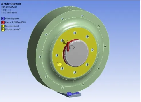
Another important point of finite element model is to determine the boundary conditions. Support points, loading conditions and temperature can be given as an example for boundary conditions. There are one fixed support, one applied force and two displacements in the analysis. These are shown in Figure 2.7 and 2.8. Fixed support of road wheel is shown as ‘A’ region which is coloured purple was determined as the place where road wheel and steel track contacted each other. Radial load is shown as ‘B’ region that is coloured red. Displacements as support points are shown as ‘D’ and ‘C’ regions which are coloured yellow in Figure 2.7 and 2.8. While these regions enable Y coordinate to be movable, they hinder the movement of X and Z coordinates. The reason is to examine the effects of radial force on the road wheel correctly.
Figure 2.7 Front side boundary conditions of road wheel
Figure 2.8 Back side boundary conditions of road wheel
There are different kinds of manufacturing process for aluminum road wheels such as casting or forging. Aluminum road wheels of T-155 Firtina Howitzer are formed by spin flow forming (spin rolling) method. Therefore, longitudinal unnotched forged fatigue data which is shown in Table 2.1 were selected to use in finite element analysis to calculate the fatigue life of aluminum road wheel and these inputs are entered into engineering data section in ANSYS Workbench software.
In the literature, it is found that axial loading fatigue test data of regular forging 2014 – T6 aluminum alloy properties were determined by D.A. Paul and D.Y. Wang [17]. The purpose of their project is to obtain the fatigue and static properties of unnotched and notched regular forgings of the aluminum alloys. In their experimental study, fatigue data were obtained by using fatigue testing machine in an axial loading. Relationship between alternating stress and fatigue life values of aluminum 2014 – T6 are indicated in Table 2.1. [17]
Table 2.1 Axial loading fatigue test data of hand forged 2014 – T6 aluminum alloy at stress ratio A=∞ [17]
Longitudinal Unnotched Specimen
Specimen No. Alternating Stress in ± MPa Cycles to Rupture
A4L – 31 165,47 19,097,200 A4L – 14 172,36 14,268,800 A4L – 15 179,26 9,277,100 A4L – 25 179,26 7,910,100 A4L – 34 186,15 2,790,700 A4L – 33 193 469,300 A4L – 13 193 565,000 A4L – 23 220,63 473,900 A4L – 22 248,21 150,600 A4L – 35 248,21 108,100 A4L – 32 268,89 58,100 A4L – 12 289,57 53,500 A4L – 24 289,57 45,500
Figure 2.9 S-N curve of hand forged aluminum alloy 2014 – T6
Mechanical and fatigue properties of aluminum 2014 – T6 which were entered to ANSYS engineering data sources are shown in snapshots as Figure 2.10 and 2.11, respectively. These data were used in stress and fatigue life analysis of road wheel. Yield and tensile strength of road wheel which was given by manufacturer were used in the analysis.
Figure 2.10 Mechanical properties of hand forged aluminum 2014 – T6 on ANSYS workbench software
Figure 2.11 Typical S-N diagram of aluminum 2014 – T6 on ANSYS workbench software
2.2 Fatigue Analysis
Fatigue analysis is used to predict service life of the mechanical parts. When mechanical parts are exposed to repeated stresses or strains, weakened region is occurred by cyclic stress in the materials. Hence, after sufficient number of stress fluctuations, there will be cracks or fracture on the materials. All of the metals have fatigue behavior and S-N diagrams are generated by fatigue experiments. Fatigue
life (N) is determined by applying different stresses (S) to test specimens so S-N curves are derived from testing many times of fatigue experiments. Example of S-N curve is shown in Figure 2.12. 𝑆𝑎 = 𝜎𝑎 represents alternating stress amplitude, 𝑁𝑓 represents number of cycles and 𝑆𝑒= 𝜎𝑒 represents endurance limit of materials. Endurance limit can be occurred in some materials such as steel. When stress is applied below the endurance limit to the materials, they reach infinite fatigue life. [18]
Figure 2.12 Representation of S-N curve [18]
Stress range, alternating stress and mean stress are important variables to determine fatigue behavior of materials. Following formulas and graphical representation are used to calculate applied stress in fatigue analysis. Stress range (2.1), alternating stress (2.2) and means stress (2.3) formula are shown below respectively. [18] ∆𝜎 = 𝜎𝑚𝑎𝑥 − 𝜎𝑚𝑖𝑛 (2.1) 𝜎𝑎 = ∆𝜎 2 = 𝜎𝑚𝑎𝑥−𝜎𝑚𝑖𝑛 2 (2.2) 𝜎𝑚 = 𝜎𝑚𝑎𝑥+𝜎𝑚𝑖𝑛 2 (2.3)
Figure 2.13 Mean stress effects [18]
Figure 2.14 Applied stress types of fatigue analysis [18]
𝑅 = 𝜎𝑚𝑖𝑛
𝜎𝑚𝑎𝑥 (2.4)
𝐴 = 𝜎𝑎
𝜎𝑚 (2.5)
Types of applied stress for fatigue analysis are shown in Figure 2.14. Fully reserved means that tensile and compressive forces are applied together, zero to max means that only tensile forces is applied and zero to min means that only
compressive forces are applied in fatigue analysis. Stress ratio (2.4) and amplitude ratio (2.5) formulas are shown above respectively.
In this study, FEA software tools were used to analyse stress and fatigue life of the parts. The known fatigue properties of aluminum alloy 2014 – T6 from program library is applied to the road wheel.
Road wheel may be exposed to various loads, they are called as radial, bending and torsion. Fatigue behavior of road wheel can be changed by all of forces. When the self-propelled howitzer is maneuvered to right or left side, it can be subjected to different torsion and bending forces. In this study, only the effect of radial force, the most important one, is investigated to analyse fatigue behavior of road wheel. Therefore, maximum and minimum radial forces affecting the road wheel and fatigue behavior of road wheel were determined.
Equivalent stress, total deformation, maximum principal elastic strain and fatigue life were analysed for aluminum road wheel and test specimen by using the boundary conditions on FEA software. Since the fatigued parts are exposed to variable loads, mean stress is considered in the calculation generally. There are three types of mean stress approaches which are Soderberg Criteria that is used for fatigue analysis of low temperature materials, Goodman Criteria that is used for fatigue analysis of brittle materials and Gerber Criteria that is used for fatigue analysis of ductile materials. Since ductility is a featured mechanical property of the aluminum, Gerber Criteria was selected to made fatigue analysis of aluminum road wheel in this study.
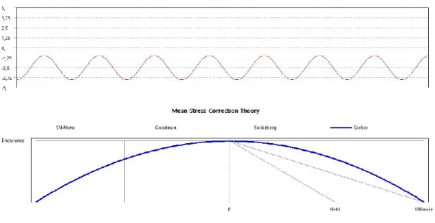
Fatigue of road wheel test specimen was analysed with constant amplitude load and Gerber criteria was selected as mean stress theory which are shown in Figure 2.15. When entering the loading ratio coefficient to software for fatigue life analysis, the following chart was consisted. Scale factor should be set ‘-1’ in this section to apply compression stress to road wheel. Therefore, the constant amplitude load appears below zero in the graph.
Figure 2.15 Constant amplitude load ratio and mean stress correction theory
2.3 Results of Finite Element Stress Analysis on Road Wheel
The von – Mises yield criterion is used to determine equivalent stress on the aluminum road wheel in this study. When ductile materials are subjected to complex loading, generally the von-Mises stress is used for static analyses. The uniaxial radial load causes different types of stresses due to the geometry of the road wheel and von – Mises stress can be approved for analysis. All in all, yield strength obtained from uniaxial tensile test of Al 2014 – T6 is compared to von – Mises equivalent stress which was calculated by using the ANSYS software for road wheel and the load which caused the plastic deformation on the road wheel was determined as the maximum load.
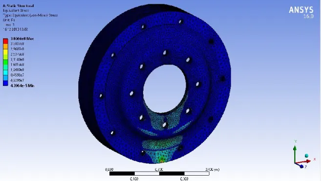
Stress analysis was used to predict fatigue life of aluminum road wheel in this study. A static analysis on the road wheel has been performed with using maximum load (23,400 Kg) which is the load first permanent deformation has been observed. A road wheel statically loaded up to a value of 23,400 Kg is shown in Figure 2.16. All other applied loadings to road wheel to determine the maximum stress value in the region of the test sample and maximum stress values on the road wheel are shown Table 2.2.
Figure 2.16 Equivalent stress (von-Mises) of aluminum road wheel
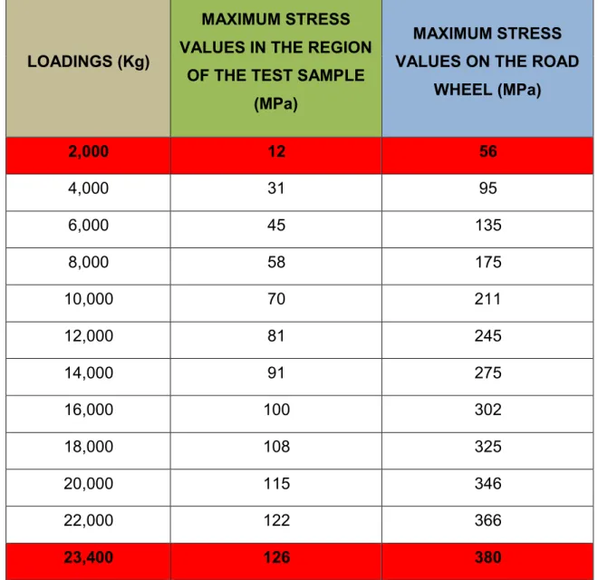
When stress analysis is performed at 2,000 Kg minimum static loading applied to the road wheel, the maximum stress on the lower surface of road wheel is 56 MPa and maximum stress on the test sample region is 12 MPa. When 23,400 Kg maximum static loading is applied to road wheel, maximum stress on the lower surface is 380 MPa and maximum stress on the test sample region is 126 MPa. This value (380 MPa) corresponds to the point that the road wheel goes to permanent deformation. Because the test specimen could not be machined from the lower surface of the road wheel where the maximum stress has occurred, it was taken from the highest wall thickness of the road wheel which is the radially load affected area.
When calculating the alternating stress to use in fatigue analysis and test, it was obviously seen that the maximum stress developed on the test specimen region of road wheel has occurred very small comparatively. Assuming that the road wheel could be worked under much harder loading conditions so alternating stress is recalculated based on these conditions. As a result, maximum stress was selected as close as possible to 380 MPa which is the starting of the permanent deformation of road wheel. So, 324 MPa was designated as maximum stress values to use test specimen fatigue analysis. On the other hand, minimum stress
would experience at the test specimen region. Even tough maximum stress (56 MPa) has been reached at that region, the minimum load to calculate alternating stress was preferred as 80 MPa. As a result, maximum stress was designated as 324 MPa and minimum stress was designated as 80 MPa for determination of alternating stress of road wheel test specimen.
Table 2.2 Calculated stress values by FEA for aluminum road wheel
LOADINGS (Kg)
MAXIMUM STRESS VALUES IN THE REGION
OF THE TEST SAMPLE (MPa)
MAXIMUM STRESS VALUES ON THE ROAD
WHEEL (MPa) 2,000 12 56 4,000 31 95 6,000 45 135 8,000 58 175 10,000 70 211 12,000 81 245 14,000 91 275 16,000 100 302 18,000 108 325 20,000 115 346 22,000 122 366 23,400 126 380
Maximum total deformation region that is in red area is shown in Figure 2.17 and maximum total deformation of road wheel was determined as 0,39 mm.
Figure 2.17 Total deformation of road wheel
Maximum principal elastic strain of road wheel is shown in Figure 2.18 and value of maximum elastic strain was 2,622 mm.
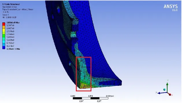
When the cross section of road wheel is examined, the stress distribution inside in the region which is indicated by light blue color on the stress scale is in between 84 MPa and 126 MPa. Therefore, it was decided to take the test samples from this part of the road wheel since the highest radial stress value indicated by a red frame in Figure 2.19 was in this section. Regional radial stress distribution is clearly being displayed in Figure 2.20.
Figure 2.19 Stress region in radial loading
2.4 Results of Finite Element Fatigue Analysis of Test Specimen
Considering 80 MPa and 324 MPa radial stress and test coupon’s dimensions according to ASTM E466/E606 standards, the maximum and minimum compression load to be applied for fatigue test were recalculated. The minimum compressive force was calculated for the 80 MPa and it was found as 210 Kg. Maximum compressive force was calculated for 324 MPa and determined as 850 Kg. Maximum and minimum loading of test specimen at static analysis is shown in Figure 2.21 and 2.22. The alternating stress which was applied at the fatigue test of test specimen was calculated as 122 MPa. Alternating stress formula (2.4) and calculation are shown below.
𝜎𝑎 = ∆𝜎 2 = 𝜎𝑚𝑎𝑥−𝜎𝑚𝑖𝑛 2 (2.4) 𝜎𝑚𝑎𝑥 = 324 𝑀𝑃𝑎 (𝑎𝑡 850 𝐾𝑔 𝐿𝑜𝑎𝑑𝑖𝑛𝑔) (2.5) 𝜎𝑚𝑖𝑛 = 80 𝑀𝑃𝑎 (𝑎𝑡 210 𝐾𝑔 𝐿𝑜𝑎𝑑𝑖𝑛𝑔) (2.6) 𝜎𝑎 = 324−80 2 (2.7) 𝜎𝑎 = 122 𝑀𝑃𝑎 (2.8)
Figure 2.22 Static analysis of test specimen at maximum loading
When fatigue of test specimen was analysed between compression load of 210 Kg and 850 Kg, it was found that infinite fatigue life between these loads. No fatigue has been observed in the middle part of the test specimens on which 122 MPa alternating stress was applied. Fatigue result of test specimen is shown in Figure 2.23.
3. EXPERIMENTAL
This chapter includes experimental test setup, material specifications, fatigue testing and non-destructive test results of the specimens. In the present study, stress and fatigue analysis of aluminum alloy road wheel were carried out by using finite element analysis (FEA) method. Then, FEA results obtained were verified by using experimental results. Non-destructive methods were utilized to observe the difference between fatigued and non-fatigued parts. Experimental methods are explained in following sections in detail.
3.1 Material Specifications
Aluminum and its alloys are one of the most multifaceted, low-cost and conspicuous metallic materials in engineering applications. This material has wide usage area from soft and flexible aluminum foil to demanding engineering applications. [19]
When density characteristic of steel and aluminum are compared to each other, aluminum has 2,7 𝑔𝑟
𝑐𝑚3
⁄ and steel has 7,85 𝑔𝑟⁄𝑐𝑚3. Therefore, there is approximately three times difference in weight between them, hence aluminum gains lightweight characteristic from this circumstance. When high strength of aluminum alloys is combined with light weight characteristic, it allows to design and produce of strong and lightweight structures. Especially, this advantageous is effective for moving vehicles such as spacecraft, aircraft, and all types of land and watercraft vehicles. [19]
Aluminum has the property of high oxidation resistance in contrast to steel. In aluminum material surfaces, there is a very thin inert oxide layer that is colorless and transparent. The thin oxide layer is not seen by the naked eye and this thin layer prevents progressing of oxidation to inner parts of material. Aluminum oxide film does not flake off unlike rusted steel. If this protective layer is damaged, it will renew itself immediately. [19]
There are significant properties for aluminum so it has wide usage area for all type of industries. For instance, aluminum has highly reflective surface so there are
electromagnetic waves. Also electrical and thermal conductivity characteristic of aluminum is excellent and non-ferromagnetic property of aluminum plays an important role for electronics and electrical industries. [19]
There is an aluminum alloy nomenclatures which is mostly identified by United States. Aluminum alloy materials are separated into two parts, they are called as wrought alloys and cast alloys. A four digit numerical designation system is used for wrought alloys. There are nine different groups such as 1000, 2000…9000. For example, 2000 series alloys include copper which is principal alloying element. Since their high strength property is precious, this series is widely used in aerospace/aircraft industry. Yield strength of 2XXX series is as high as 455 MPa. Casting and foundry ingots are also designated by four digit system which is incorporated by a decimal point. For example, 3XX.X series include silicon with added copper and/or magnesium. [19]
Temper designation of aluminum includes some letters and numbers to explain properties of heat treatments. Meaning of letters and numbers is important to understand characteristic of aluminum tempers. These designations give information to users about general manner that how aluminum alloys mechanically and thermally treated. Designations do not demonstrate threated types and temperatures of thermal treatments. The first character is capital letter which indicates the general class of treatment such as F, O, H, W or T. When these capital letter are explained, ‘F’ means fabricated product forms of aluminum alloy, ‘O’ means annealed products, ‘H’ means strain hardened products, ‘W’ means solution heat threated products, ‘T’ means that aluminum alloys are thermally treated to produce stable tempers other than capital letters. The first numbers after T demonstrate the heat treatment type of aluminum. For example, T6 means that alloy has been solution heat threated without any significant cold working. It means also artificially aged to achieve precipitation hardening. [20]
Road wheel originally made by forged steel of T-155 Firtina Howitzer was manufactured in this case by 2014 - T6 aluminum alloy material. This material can be used easily for the applications that are requiring high strength and hardness. 2000 series aluminum alloys are effective in damage tolerance applications and also they have higher temperature working capability.
General chemical composition and mechanical properties of aluminum alloy 2014 – T6 are shown in Table 3.1 and Table 3.2 respectively. However, the road wheel manufacturer has given fairly different yield strength and ultimate strength. For example, after T6 heat treatment, yield strength of road wheel was reported as 380 MPa, tensile strength was 440 MPa and elongation was %10. These values were used to execute stress analysis in finite element method.
Table 3.1 Chemical composition of aluminum alloy of 2014 – T6 [21] Al Alloy Cu Mg Zn Mn Si Fe Cr Ti Zr 2014 3.9-5.0 0.2-0.8 0.25 (max) 0.4-1.2 0.5-1.2 0.7 (max) 0.10 (max) 0.15 (max) -
Table 3.2 Mechanical properties of aluminum alloy of 2014 – T6 [21]
Al Alloy Temper Density (g/cm3) Elastic modulus (GPa) Tensile Properties HCF limit (MPa) Fracture toughness (MPa√m) Yield (MPa) Tensile (MPa) % El 2014 T6 2.80 72.4 415 485 13 125 26.4 (T651)
3.2 Test Specimens and Test Setup
Test specimens of aluminum road wheel and test setup are explained in this section. First of all, the test specimens were cut from the outer side of road wheel and this location is indicated in Figure 3.1. The test specimens were manufactured according to ASTM E606 standards recommended for low-cycle fatigue
assemble the test specimens to fatigue test machine. The test specimens subjected to uniaxial forces were used to determine fatigue properties of nominally homogeneous aluminum materials. The test specimens of road wheel were manufactured by considering the aspect ratio and recommended dimensions of test sample are depicted in Figure 3.2. Test specimens of road wheel and steel adapters are shown in Figure 3.3 and 3.4 respectively. Technical drawing of test specimens and steel adapters are indicated in Appendix 1, Appendix 2 and Appendix 3.
Figure 3.1 Representation of the test sample region on road wheel
Figure 3.2 Recommended low-cycle fatigue specimen in ASTM E606 standard [23]
Figure 3.3 Test specimens of road wheel
Figure 3.4 Test specimens of road wheel with steel assembly adapters Fatigue testing machine used for test specimens is shown in Figure 3.5 and 3.6. Fatigue test was applied to three test specimens between 210 Kg and 850 Kg load under 10 Hz frequency and 1,500,000 cycles. MTS Servo hydraulic test system (100 kN) is the machine that was used for static and dynamic material and component testing. Specifications of this test machine are suitable so it was
selected to analyse road wheel specimens. The fatigue test machine which was placed in Karabuk Iron and Steel Institute was used in this study.
Technical specification of testing machine is listed in below. [24] Maximum loading capacity is 100 kN,
5.8 - 16.5 mm diameter round sample binding capacity, Flat sample binding capacity up to 0 - 14.2 mm,
100 kN pressure plates suitable for static and dynamic loading,
3-point bending equipment with adjustable height of 30 - 250 mm for 100 kN loading,
Measurement of fracture toughness and crack feed rates according to CT (Compact tension) and 3 point bending equipment with COD extensometer, Dynamic extensometer capable of operating at temperatures up to 80 °C -
+175 °C, moving between +5 mm and -2.5 mm with a first measurement length of 12.5 mm, 25 mm and 50 mm,
An external LVDT (deflectometer) capable of operating at temperatures between 40 °C and +100 °C and measuring at least ± 15mm,
High temperature furnace and temperature control unit with a measuring length of 50 mm, operating up to 1400 °C.
3.3 Testing
The test specimens were subjected to fatigue test at Karabuk University Iron and Steel Institute. The specimens were connected to the hydraulic gripper of the test machine with the aid of steel adapters. The connection of test specimen with steel adapters is shown in Figure 3.6. Compression load between 2,059 kN (210 Kg) and 8,335 kN (850 Kg) at 10 Hz frequency and 1,500,000 cycles were applied to 3 number of test specimens. Since the maximum velocity of aforementioned Howitzer is known 65 Km/h, the revolution of the road wheel is calculated at this rate of speed as 9 rev/sec. Therefore, frequency of fatigue test was selected roughly 10 Hz. Experimental fatigue test was limited to the number of cycles of 1,500,000. Limitation of cycles at fatigue test was due to time and cost factors. Alternating stress which is 122 MPa to be applied on the test specimen was calculated by the compression load between 210 Kg and 850 Kg.
Over the course of fatigue test, no damage was observed on the images taken from the samples every 250,000 cycles with the Nikon ShuttlePix digital microscope. Totally, 6 images were taken per sample and cracks that may occur on the surface were not observed. Example of digital microscope surface image of test specimen is shown in Figure 3.7.
3.4 Non-destructive Test Methods of Specimens
Non-destructive testing (NDT) allows component to be reused that is an important advantage for engineering. This method includes some process for inspecting, testing or evaluating materials, components or assemblies. The internal and external cracks can be observed without destroying the part. Radiographic, liquid penetrant and eddy current testing methods were mostly used to observe if crack initiation of test specimens happens in this study. These tests were applied to specimens in Turkish Standards Institution (TSE), Non – destructive Testing Laboratory in Gebze. NDT methods used in this study are explained below in detail.
3.4.1 Radiographic testing (RT)
Radiographic testing was applied to check the internal crack of the parts which were subjected to a fatigue testing. This test is utilized to observe inner structure of objects in very wide area such as medicine, engineering or security. Working principle of this method is that penetrating radiation is sent to object and it passes through the object. Recording tool is placed against the opposite side of object. This recording media includes industrial x-ray film or one of several types of digital radiation detectors. Discontinuities in the material such as crack, pore, slag, residue or voids can be detected by using this method. [25; 26]
In radiographic testing section, firstly, two different radiographic tests were applied to test specimens so there are two images obtained. Type of operation-1 was low duration. Type of operation-2 was more than 15 seconds from operation-1 and the parts were shot by rotating 90 degrees. ‘Y’ points out the ones that were exposed to fatigued test specimens, marked as Y1, Y2 and Y3. ‘S’ points out the ones that were exposed to non-fatigued parts, marked as S1, S2 and S3. The numbers below the parts are compatible with the fatigue test. Operation-1 and Operation-2 are shown in Figure 3.8 and 3.9, respectively.
Figure 3.8 Radiographic test of road wheel fatigue test specimens (Operation-1)
Figure 3.9 Radiographic test of road wheel fatigue test specimens (Operation-2) 3.4.2 Liquid penetrant testing (PT)
Liquid penetrant testing was applied to check surface crack of the part. This test is one of the most popular and widely applied inspection method to observe surface breaking imperfections in the industry. There are three used aerosol can which are cleaner, penetrant and developer. This method is applied with six basic steps;
these are pre-cleaning part, applying penetrant, removing penetrant, applying developer, evaluating indications and post cleaning part respectively. When very low viscosity liquid which is penetrant is applied to the surface of the part, it will penetrate into voids or cracks of surface. After the excess penetrant is removed, penetrant remaining in the voids will flow back out with creating indication. When this result is examined, defective zones are determined. [25; 27]
The test specimens which were exposed to fatigue loading were also examined by liquid penetrant testing. They are marked as Y1, Y2 and Y3 which are shown in Figure 3.10. Since no fatigue symptoms or cracks were observed in the fatigued parts, Non-fatigued test specimens were not examined by liquid penetrant testing.
Figure 3.10 Liquid penetrant inspection of road wheel fatigued test specimens 3.4.3 Eddy current testing
Eddy current testing was applied to determine crack initiations of the fatigued test specimen. In this technique, electric current or magnetic field into conductive part
into a conductive test piece is induced by an alternating current coil, the magnetic flux field creates a small current so a magnetic field is generated around an electric current. The flow pattern of this secondary current is called an eddy current. Eddy current is affected when it encounters a discontinuity in the test piece. The change in the eddy current density can be detected and used to characterize the discontinuity causing that change. [25]
The specimens were put into the eddy current testing, but no signal was received by test equipment, so no any image was obtained.
3.4.4 Scanning electron microscope (SEM)
Scanning electron microscope (SEM) was used to examine micro structure of fatigued and non-fatigued specimens and characterize the surface morphology and particle size. The main purpose of scanning electron microscope is that creating an image with scanning a focused beam of high energy electrons to generate variety of signals at the surface of solid specimen. This electron and sample interactions give some information about external morphology, chemical composition, crystalline structure and orientation of materials. Scanning electron microscope which is placed in Gazi University Faculty of Technology was used in this study. The brand of microscope is Jeol JEM 6060 LV that is shown in Figure 3.11 and technical specification is explained below. [28; 29]
The scanning electron microscope (SEM) is fully digital and works with computer control.
K-type tungsten filament is used as the electron source.
It operates with 5-axis motorized Cartesian control (X=20 mm, Y=10 mm, Z=40 mm, Tilt = -10 10 and + 90 20, Rotation = 360y).
A 3.5 nm resolution is obtained with 30 kV accelerator voltage and 8 mm operating range conditions.
It is possible to conduct an examination in the range of 0.5 kV-30 kV accelerator voltage.
It has a magnification capacity of 8x - 300.000X. (If the working range is 48 mm and the acceleration voltage is 10kV, it goes down to 5x magnification.)
Figure 3.11 Jeol JEM 6060 LV scanning electron microscope
There are five images for both separately fatigued test and non-fatigued test specimens in SEM analysis, see between Figure 3.12 and Figure 3.16. These inspections were carried out in 30X, 100X, 500X, 1000X and 2500X magnification for fatigue and non-fatigued parts.
In order to examine the surface of each fatigued test specimens, specimens were cut from mid-section and polished. When images that were taken from scanning electron microscope (SEM) were examined, it was found that no change in the grain size and not any discontinuity on fatigued and non-fatigued parts.
(a) (b)
Figure 3.12 SEM analysis of (a) fatigued & (b) non-fatigued test specimens in 30x
(a) (b)
Figure 3.13 SEM analysis of (a) fatigued & (b) non-fatigued test specimen in 100x
(a) (b)
(a) (b)
Figure 3.15 SEM analysis of (a) fatigued & (b) non-fatigued test specimen in 1000x
(a) (b)
Figure 3.16 SEM analysis of (a) fatigued & (b) non-fatigued test specimens in 2500x
3.4.5 Optical microscope
In optical microscope, one or a series lenses are used to magnify images of small objects with the aid of visible light. Optical microscope is also named as light microscope. LEICA DM4000 M optical microscope was used to observe grain size and micro structure of aluminum alloy 2014 – T6 fatigued and non-fatigued test specimens. In LEICA microscope, there are six objective turrets which are 2.5x, 5x, 10x, 20x, 50x and 100x. The LEICA DM4000 M optical microscope which was used in this study is shown Figure 3.17. This optical microscope is placed in Gazi University Faculty of Technology. [30]
Figure 3.17 LEICA DM4000 M optical microscope
There are three images for both separately fatigued test and non-fatigued test in optical microscope analysis, see between Figure 3.18 and Figure 3.20. This test was applied in 50X, 100X and 200X for fatigued and non-fatigued parts.
(a) (b)
Figure 3.18 Optical microscope analysis of (a) fatigued and (b) non-fatigued test specimen in 50x
(a) (b)
Figure 3.19 Optical microscope analysis of (a) fatigued and (b) non-fatigued test specimen in 100x
(a) (b)
Figure 3.20 Optical microscope analysis of (a) fatigued and (b) non-fatigued test specimen in 200x
The surfaces were analysed by optical microscope and when images that were taken from microscope were examined, it was found that no change in the grain size and not any discontinuity on fatigued and non-fatigued parts.
4. RESULTS AND DISCUSSION
This chapter evaluates the experimental and numerical analysis results in detail. Numerical fatigue and static stress analysis of aluminum road wheel were carried out by using ANSYS software and then experimental fatigue test was executed according to ASTM E466/E606 standards using these numerical results obtained. After experimental fatigue test, all test specimens were cut from the middle of gage length and inspected through non-destructive methods (NDT) to observe the grain surfaces for checking if any crack initiation has occurred. Non-destructive inspection has been executed with the method of radiography, scanning electron microscope (SEM) and optic microscope.
4.1 Results obtained from Fatigue Prediction and Experimental Analysis There were three important points that were emphasized in previous section. Considering these points, stress and fatigue analysis of aluminum road wheel are explained in this section.
First of all, the road wheel stress analysis has been executed to determine the maximum stress to be reached due to static weight of 2,000 Kg experienced by per wheel of the vehicle which totally weighs of 47,5 tones and maximum equivalent stress (von-Mises) just before showing permanent deformation under loading on aluminum road wheel. It was found that maximum compression stress due to static dead weight is going to be 56 MPa and on the other hand maximum compression stress that the wheel is able to carry without permanent deformation is going to be 380 MPa under 23,400 Kg static loading. This maximum compression stress also corresponds to the yield strength of Al 2014 – T6 which is 380 MPa.
It is observed that this maximum stress of 380 MPa occurs at the bottom surface of aluminum road wheel. Stress distribution and stress values are shown in Figure 4.1. Since it was not possible to get the test specimens from the bottom place of the road wheel due to the thickness problem, it was decided to get and machine the test specimens from the main body of the wheel in radial direction. The region of test specimen to be cut is shown Figure 4.2.
Figure 4.1 Equivalent stress (von-Mises) of aluminum road wheel

![Table 2.1 Axial loading fatigue test data of hand forged 2014 – T6 aluminum alloy at stress ratio A=∞ [17]](https://thumb-eu.123doks.com/thumbv2/9libnet/3979477.52915/27.892.139.776.381.1009/table-axial-loading-fatigue-forged-aluminum-alloy-stress.webp)

![Figure 2.12 Representation of S-N curve [18]](https://thumb-eu.123doks.com/thumbv2/9libnet/3979477.52915/30.892.143.760.343.643/figure-representation-of-s-n-curve.webp)
![Figure 2.13 Mean stress effects [18]](https://thumb-eu.123doks.com/thumbv2/9libnet/3979477.52915/31.892.229.686.137.434/figure-mean-stress-effects.webp)