THE CRYSTALLIZATION BEHAVIOUR
OF
ISOTACTIC POLYBUTENE-1
A THESIS SUBMITTED TO THE DEPARTMENT OF CHEMISTRY
AND THE INSTITUTE OF ENGINEERING AND SCIENCE OF BILKENT UNIVERSITY
IN PARTIAL FULFILLMENT OF THE REQUIREMENTS FOR THE DEGREE OF MASTER OF SCIENCE
BY
HACI BAYRAM ERDEM
I certify that I read this thesis and that in my opinion it is fully adequate, in scope and in quality, as a thesis for the degree of Master of Science.
_______________________________
Asst. Prof. Dr. Gürhan Kalay (Supervisor)
I certify that I read this thesis and that in my opinion it is fully adequate, in scope and in quality, as a thesis for the degree of Master of Science.
_______________________________
Prof. Dr. Şefik Süzer
I certify that I read this thesis and that in my opinion it is fully adequate, in scope and in quality, as a thesis for the degree of Master of Science.
_______________________________
Assoc. Prof. Dr. C. Hakan Gür
Approved for Institute of Engineering and Science.
________________________________ Prof. Dr. Mehmet Baray
ABSTRACT
THE CRYSTALLIZATION BEHAVIOUR OF ISOTACTIC POLYBUTENE-1
Haci Bayram Erdem M.S in Chemistry
Supervisor: Assist. Prof. Dr. Gürhan Kalay August 2002
The crystallization behaviour of different commercial grades of isotactic polybutene-1 was investigated and an experimental set-up was designed for this research study. The experimental set-up constructed provides both fast-cooling of the sample and the recording of the growth of spherulites as a real time movie. The radial growth rate of the spherulites were observed to be higher for the grades with higher molecular weights. The results were found to fit to the Lauritzenn-Hoffman crystallization theory, and this theory is used to calculate the lateral surface free energy, σ, and fold surface free energy, σe. The lateral surface free energy was found to be 10.4 erg/cm2 for all the grades investigated. The fold surface free energy calculated to be between 15.5 to 17.4 erg/cm2. The fold surface free energies and the crystallization rates do not exhibit any dependence on the molecular weight of the polymer. The polymer containing nucleating agents has the highest crystallization rate. It was observed that the likelihood of deviation from spherical shape is greater for the grades with lower molecular weights.
ÖZET
İZOTAKTİK POLİBÜTEN-1’İN KRİSTALLEŞME DAVRANIŞI
Hacı Bayram Erdem Kimya Yüksek Lisans
Tez Yöneticisi: Assist. Prof. Dr. Gürhan Kalay Ağustos 2002
Polibuten-1’in dört farklı ticari türünün kristalleşme davranışı incelendi ve bu inceleme için bir deney düzeneği hazırlandı. Hazırlanan deney düzeneği, aynı zamanda numunelerin hızlı-soğutulmasını ve küresel kristal yapıların büyümesini gerçek zamanlı bir film olarak kaydedilmesini sağladı. Yarıçapsal büyüme hızlarının, büyük molekül ağırlıklı sınıflar için daha büyük olduğu gözlemlendi. Bulunan sonuçların Lauritzen-Hoffman kristalleşme teorisine uygunluğu gösterildi ve bu teori yanal yüzey serbest enerjisi, σ, ile katlanma yüzeyi serbest enerjisi, σe, değerlerini hesaplamada kullanıldı. Yanal yüzey serbest enerjisi σ’ nın bütün incelenen türler için değeri 10,4 erg/cm2 olarak bulundu. Katlanma yüzeyi serbest enerjisi değerlerinin 15,5 erg/cm2 ile 17,4 erg/cm2 arasında değiştiği hesaplandı. Katlanma yüzeyi serbest enerjisi, σe, ile kristalleşme hızının moleküler ağırlığa bağlı olmadığı görüldü. Çekirdekleşme katkı maddeleri içeren türün kristalleşme hızının incelenen türler içinde en yüksek olduğu bulundu. Küresel yapıdan sapma olasılığının, daha küçük molekül ağırlıklı sınıflar için daha yüksek olduğu gözlendi.
Anahtar Kelimeler : polibüten-1, Lauritzen-Hoffman teorisi, yarıçapsal büyüme hızı, çekirdekleşme katkı maddesi, kristalleşme hızı, polimer kristalleşmesi
ACKNOWLEDGEMENT
I warmly thank Asst. Prof. Dr. Gurhan Kalay, for his great help and supervision throughout my studies.
TABLE OF CONTENTS SIGNATURE PAGE………..ii ABSTRACT………iii ÖZET………..iv ACKNOWLEDGEMENT………v TABLE OF CONTENTS………..vi LIST OF FIGURES………ix LIST OF TABLES……….xi
LIST OF MOVIES INCLUDED IN THE APPENDIX-1………...xii
CHAPTER-1. INTRODUCTION………...1
CHAPTER-2. LITERATURE REVIEW……….3
2.1. Introduction ………3
2.2. Synthesis of Isotactic Polybutene-1………3
2.2.1. Properties of Monomer ………..3
2.2.2. Synthesis of iPB-1………..4
2.3. Polymorphmism of Isotactic Polybutene-1………...5
2.4. Form-II to Form-1 Crystal Transformation………9
2.4.1. Introduction………9
2.4.2. The Rate of Transformation from Form-II to Form-I………10
2.5. Polymer Crystallization……….13
2.5.1. Introduction………13
2.5.2. Crystallization During Polymerization………..14
2.5.3. Strain Induced Crystallization………15
2.5.3.1.Crystallization from Solutions under Strain………..15
2.5.3.2. Crystallization from Melts under Strain………..15
2.5.4. Crystallization under Quiescent Condition………..16
2.5.4.1.Crystallization from Quiescent Solutions………16
2.5.4.2.1. Fringed Micelle Model……….18
2.5.4.2.2. Spherulites………19
2.5.4.2.3. Nucleation………21
2.5.5. Kinetics of Lateral Crystal Growth………23
2.5.1. Lauritzen-Hoffman secondary Nucleation Theory………23
2.5.2. Regimes of Growth………27
2.5.3. Spherulite Growth rate vs Temperature………27
2.5.6. Bulk Crystallization Kinetics and Avrami Equation……….29
2.6. Supermolecular Structure of iPB-1 ……….32
2.7. Applications of Isotactic Polybutene-1………33
CHAPTER-3. EXPERIMENTAL PROCEDURE AND THE DESCRIPTION OF THE CRYSTALLIZATION CALCULATIONS………..34
3.1 Materials………34
3.2 DSC Characterization………...35
3.3 FT-IR Measurements………35
3.4 Spherulite Growth Rate Measurements………35
3.4.1. Microtomy………..35
3.4.2. Crystallization Experiments………...36
3.4.3. Spherulite Growth Rate (SGR) Set-up………...36
3.5 The Measurement of Spherulite Growth Rate……….39
3.6 Preperation of the L-H Plots and Calculation of the Regime Constants..40
3.7 Calculation of the Overall Crystallization and Avrami Analysis……….41
CHAPTER-4. RESULTS AND DISSCUSSION……….43
4.1. Form-II to Form-I Transformation by FTIR………43
4.2. DSC Studies……….44
4.3. Spherulite Growth Rate Studies………...45
4.3.1. Grade PB 0110……….45
4.3.2. Grade PB 0300 ………49
4.3.3. Grade PB 0400……….53
4.5 Effect of Molecular Weight on the Fold Surface Free Energy σe…………...63
4.6 Avrami Analysis ………67
4.7 Effect of Molecular Weight on the Overall Crystallization Rate…………...69
CHAPTER-5. CONCLUSIONS and FUTURE WORK……….71
5.1 Conclusions……….71
5.2 Future Work………72
CHAPTER-6. REFERENCES………..73
LIST OF FIGURES
Figure 2.1 Molecular Structure of Isotactic Polybutene-1………...3 Figure 2.2. Helical Conformations of (a)Form-1,3/1 helix,(b) Form-II, 11/3 helix..6
Figure 2.3. DSC Thermograms of Various Polymorphous of iPB-1………7 Figure 2.4. X-Ray Diffraction Patterns of Various Polymorphous of iPB-1……...7
Figure 2.5. Interconversion Between Polymorphs of iPB-1……….…………8 Figure 2.6. (a) Shirankage of Square Form-II Crystal upon Conversion to Form-I .9
(b) Development of Cracks and Elongated Domains……….9
Figure 2.7. Percentage Conversion to stable Form-I as a Function of Annealing Time for Different Take up Speeds ………..11
Figure 2.8. IR Spectra of iPB-1 aged for various times…… ………...12
Figure 2.9. General Behaviour of Thermodynamic Variables at the Equilibrium Melting Temperature……….13
Figure 2.10. AFM Image of The Shear region of iPB-1 Processes by SCORIM….15 Figure 2.11. Electron Micrograph of Linear Polyethylene Grown from a Solution of
Perchloroethylene………..16
Figure 2.12. Schematic Two Dimensional Representations of Models of the Fold
Surface………..17
Figure 2.13. Fringed Micelle Model of the Crystalline-Amorphous Structure of
Polymers………18
Figure 2.14. Schematic Diagram of Ordering of the Indicatrices in a Spherulite….19 Figure 2.15. Schematic Diagram of Fully Developed Spherulite Grown from the
Melt………...20
Figure 2.16. Electron Micrograph of Central Sheaf-Like Part Observed at an Early
Stage of Development of a Spherulite of iPB………...20
Figure 2.17. Free Energy of Crystal Nuclei Formation as a Function of
Temperature……….……….21
Figure 2.18. Primary and Secondary Nucleus Formation Rates as a Function of
Crystallization Temperature………..22
Figure 2.19. Scheme Illutrating the Rates of Stem Deposition During the Three
Figure 2.21. Schematic Diagram of Conversion of Growth Rate Data to L-H
Plot………..…..29
Figure 2.22. Creep Behaviour of Polyolefin Resins Compared to PB-1…………...33
Figure 3.1. Dimensions of Polymer Mould Prepared for Microtomy……….36
Figure 3.2. Schematic Diagram of SGR Set-up………..37
Figure 3.3 Close-up Picture of the SGR Set-up………..……...38
Figure 3.4 Picture of the SGR Set-up during the Experiment……..……….38
Figure 3.5. Micrograph of the Graticule……….39
Figure 3.6. Micrographs of iPB-1 Thin Films Crystallized at 70 oC………..39
Figure 4.1. IR Spectra of iPB-1 Grade PB0100 vs.Various ageing times at room temperature………...41
Figure 4.2. Micrographs of Grade PB0110……….45
Figure 4.3. Growth of Spherulites of PB0110………47
Figure 4.4. Radial Growth Rate and L-H Plot for PB0110……….48
Figure 4.5. Micrographs of Grade PB0300……….50
Figure 4.6. Growth of Spherulites of PB0300……….51
Figure 4.7. Radial Growth Rate and L-H Plot for PB0300……….51
Figure 4.8. Micrographs of Grade PB0400……….53
Figure 4.9. Epitaxial Crystallization and Non-spherical Entities………54
Figure 4.10. Growth of Spherulites of PB0400……….55
Figure 4.11. Radial Growth Rate and L-H Plot forPB0400………..56
Figure 4.12. Micrographs of Grade PB0800……….57
Figure 4.13. Ringed Spherulites for PB0800……….58
Figure 4.14. Growth of Spherulites of PB0800……….59
Figure 4.15. Radial Growth Rate and L-H Plot for PB0800……….60
Figure 4.16. Fit of Equation 2.13 to the Spherulitic Growth Rate for iPB-1………61
Figure 4.17. Avrami Analysis and Fit of the Avrami Equation to Overalll Crystallization Change vs. Time………….………..68
Figure 4.18. (a),(b),(c),(d) Micrographs of PB0110, PB0300, PB0400, PB0800
crystallized at 70 oC for 90 seconds, respectively. (e)Q vs.Time plots for PB0110, PB0300, PB0400 and PB0800 at 70 oC(f)Spherulite Size vs. time plots for PB0110, PB0300, PB0400 and PB0800 at 70 oC….70
LIST OF TABLES
Table 2.1. Millions of Pounds Per Year of Butene-1 for Chemical Use……….4
Table 2.2. Avrami Exponents for Various Geometries, Nucleation Types and Rate
Determining Step for Crystal Growth G………..31
Table 3.1. The Densities and Melt Flow Indices of the Investigated PB Grades………..34
Table 3.2. Number Average Molecular Mass, Weight Average Molecular Mass,
Polydispersities of the Grades Investigated……….34
Table 3.3. The Values of Variables for iPB-1 Used in the Calculations………41
Table 4.1. Melting Peak Temperature, Enthalpy of Fussion and Percent Crystallinity of iPB-1……….44
Table 4.2. Spherulite Growth Rates for the Grades Investigated……..…… …………..61
Table 4.3. The Experimental and Calculated Growth Rate Maximum for iPB-1 Grades.62
Table 4.4. Fold Surface Free Energy σe Values Found…..………63
Table 4.5 The comparison of results of this study and the values from the published literature for σe...………...64
Table 4.6. Previous and Recalculated Values of the Regime KIII and σe………..65
LIST OF MOVIES INCLUDED IN THE APPPENDIX-1 A- Grade PB0110 Movies 1-011pb75c.avi 2-011pb80a.avi 3-011pb85a.avi 4-011pb85b.avi 5-011p90a2.avi B-Grade PB0300 Movies 6-300pb55a.avi 7-300pb60a.avi 8-300pb65a.avi 9-300pb70a.avi 10-300pb75a.avi 11-300pb75c.avi 12-300pb80a.avi 13-300pb85a.avi 14-300pb90a.avi C-Grade PB0400 Movies 15-400pb55a.avi 16-400pb60a.avi 17-400pb65a.avi 18-400pb70a.avi 19-400pb75a.avi 20-400pb75b.avi 21-400pb75c.avi 22-400pb80a.avi 23-400pb85a.avi 24-400pb90a.avi
D-Grade PB0800 25-800pb60a.avi 26-800pb65b.avi 27-800pb70a.avi 28-800pb75a.avi 29-800pb80a.avi 30-800pb85c.avi
CHAPTER-1. INTRODUCTION
Crystallization of polymers is important since their physical and chemical properties are dependent on the level of crystallinity. When a polymer melt is cooled to a temperature between a glass transition temperature and a crystal melting point, the crystallization of polymer takes place. Crystallization of polymers are kinetically controlled and affected by the crystallization temperature, thermal history of the polymer, pressure, shearing etc. Polymers show different structural features at different length scales. In the nanometer range, polymer chains form thin plate-like structures called lamella (of the thickness around 10nm). Since the thickness of lamellae is much less than the length of the polymer molecule, chains must be folded to form the lamellae. In the micrometer range, lamellae combine and result in a sphere-like structure called spherulite. Spherulites first appear as a small dot (nucleus) and grow with a constant speed. The number of spherulites affects the mechanical properties of the polymer. Spherulites are optically anisotropic structures and can be observed under the cross-polarized light.
The purpose of this study was to investigate the crystallization behaviour of different commercial grades of isotactic polybutene-1 and to design an experimental set-up for this investigation.
The mould temperature in processing could be chosen with such crystallization data in mind to obtain products exhibiting the desired mechanical properties. For instance the stiffness (Young’s modulus) of the samples will be higher for smaller spherulite sizes than larger spherulite size samples. When toughness is important than the level of crystallization, should be kept lower by choosing the appropriate grade of polymer.
Isotactic polybutene-1 is quite an interesting polymer, i.e. it undergoes a crystal-crystal transformation upon ageing at room temperature. This crystal-crystal transformation is accompanied with the change of physical properties and development of cracks, which cause serious problems in the applications of the polymer. Therefore, polybutene-1 is not used in large quantities in comparison with the other lighter polyolefins like polyethylene and polypropylene, although isotactic
polybutene-1 has superior mechanical properties, i.e. tough, resistance to stress cracking, perfect resistance to creep even at elevated temperatures.
This thesis presents a literature review, in the next Chapter, i.e., Chapter-2. This chapter summarizes the synthesis, polymorphism, and crystal-crystal transformation of isotactic polybutene-1 and main features of the crystallization of polymers. This chapter includes a brief summary of the Lauritzen-Hoffman crystallization theory and its consequences. It also covers the previous work on the crystallization of polybutene-1 from literature.
The following chapter, Chapter-3, explains the set-up designed for this study and the methods used in crystallization calculations in Chapter-4, on the results and discussion. The experimental set-up designed for this study enables both fast cooling of the sample and record of the growth of spherulites as a real time movie. Then, the pictures can be obtained from this real time movies for further analysis.
The Chapter 4 gives the results of this study and these results are discussed on the basis of the previous literature work and Lauritzen-Hoffmann crystallization theory. The differences in the crystallization behaviour of the grades are discussed at the end of this chapter.
The final chapter summarizes the conclusions of this research together with some suggestions for a future study. A CD including the real time growth movies of the spherulites were also added as Appendix-1.
CHAPTER-2. POLYBUTENE-1 - LITEARATURE REVIEW
2.1 Introduction
Isotactic Polybutene-1 is a highly crystalline thermoplastic polymer with the crystal melting temperature (Tm) around 125 oC and the glass transition temperature (Tg) around –20 oC.1 Polybutene-1 has several attractive mechanical properties; tough, resistant to stress cracking and abrasion and retains good mechanical properties even at high temperatures.2 However, the commercial production of isotactic polybutene-1 is still small in comparison with polyethylene and polypropylene. The main reason has been the low level of monomer availability and its high price. In addition, crystalline transformation of processed articles at room temperature limits applications of iPB-1.2
Figure 2.1 : Molecular Structure of Isotactic Polybutene-13
2.2 Synthesis of Isotactic Polybutene-1
2.2.1Properties of Monomer
1-Butene (H2C=CHCH2CH3) is a colourless flammable gas with boiling point of –6 0C at 1 atm.4 Commercial production of 1-butene is either by the catalytic oligomerization of ethylene or by distillation MTBE (methyl tert-butyl ether) raffinate,5 which is a high octane blending component for gasoline. Chevron, BP Amoco and Basell (formerly Shell) produce butene-1 by ethylene oligomerization. Exxon and Texas Petrochemicals distill butene-1 from other products during the production of MTBE.2,5 More than half of the butene-1 produced is used as
polyethylene comonomer. Only 14 % of the total production in U.S.A. is used for the synthesis of polybutene-1.5
PRODUCER CAPACITY*
BP Amoco, Pasadena, Tex. 120
Chevron, Cedar Bayou, Tex. 120
Exxon, Baytown, Tex. 140
Shell, Geismar, La. 140
Texas Petrochemicals, Houston, Tex. 315
Total 835 Table 2.1: Millions of pounds per year of butene-1 for chemical use, August 16, 19995
2.2.2 Synthesis of iPB-1
Isotactic polybutene-1 is usually produced by solution polymerization of butene-1 with a Ziegler-Natta catalyst system.6 (Solway or supported type catalyst) Cationic or free-radical initiators result in atactic PB-1 that do not crystallize.4 The Synthesis of Isotactic polybutene-1 was first reported by Natta and co-workers in 1954.2 Butene-1 polymerize readily with Ziegler-Natta catalysts to high molecular weight products.7 In the early years, two component catalytic systems containing organoaluminium compounds with transition metal salt and halides were used.2 A typical polymerization of butene-1 is as follows7 : 0.049 mole TiCl4 in 100 ml hexane is poured into a 10-litre dry flask filled with nitrogen and stirred while adding 0.049 mole (Et)3Al in 50 ml hexane. Butene-1 monomer is added at a rate of 40 litre/hour and the flask is stirred continuously. As necessary, hexane is added to decrease the viscosity. At the end, the reaction is quenched by ethyl alcohol. At room temperature, this reaction gives 160 gram of polybutene-1 in 3 hours. In addition to TiCl4, chlorides of vanadium, molybdenum, tungsten and zirconium can be used in the preparation of catalysts. The metal can also be zinc or lithium instead of aluminium in the organometallic component and the alkyl group can be replaced by other alkyls such as phenyl, propyl, butyl.
Different stereospecific arrangements of PB-1 can be produced with a new kind of homogeneous Ziegler-Natta catalyst, which is composed of a group IVB metallocene and a methylaluminoxane (MAO).2 The stereoregularity of the polybutene-1 can be controlled by the nature of the transition metal and the type of the ligand.6 Stereorigid chiral ansa-metallocene catalysts with C2 symmetry results in isotactic product (e.g. Et2(Ind)2ZrCl2, CH2(Ind)2Ti(CH3)2). The products of these catalytic systems are highly isotactic and have narrow molecular weight distribution. In addition, the catalytic activities of these systems are very high.2 The metallocenes with bilateral symmetry results in syndiotactic polybutene-1. (e.g. Me(Cp)FluZrCl2, CH3CH(Cp)(Flu)ZrCl2 ).6 Achiral and symmetric metallocenes generally results in atactic polybutene-1.6 Stereoregular polybutene-1 can also be synthesized with half-titanocone/MAO, Cp*Ti(OBz)3/MAO.6 Metallocene catalysts led to tailor made polyolefins with an efficient control of molecular weight distribution as well.
In addition to the 1, poly1 can be synthesized also from butene-2.2 2-butene isomerises to butene-1 prior to propagation and the result of the reaction is polybutene-1.
2.3 Polymorpmism of Isotactic Polybutene-1
Isotactic polybutene-1 exhibits polymorphism in its crystalline structure.2,9-35 Polymorphism of isotactic polybutene-1 have been studied mainly by DSC (differential scanning calorimetry), XRD (X-ray diffractometry), FT-IR (fourier transform far infrared spectroscopy), TEM (transmission electron microscopy), AFM (atomic force microscopy), dilatometry, electron crystallography and Raman spectroscopy. Five different crystalline structures of isotactic polybutene-1 have been determined: Form-I, Form-II and Form-III, Form-I’ and Form-II’. They have different packing of chains leading to different unit cell geometries, sizes and symmetries. Thus, their physical properties like density, melting point, mechanical properties are also different.
Crystallization of melt at room temperature produces metastable Form-II. Form-II, then, gradually transforms into the stable Form-I at room temperature2 Form-I is characterized by a trigonal (hexagonal) unit cell with dimensions a=b =1.77 nm
and c(chain axis)=0.65 nm.9 Space group of the unit cell of Form-I is R3c or R3c with 3/1 helical conformation of the chains (twinned). The melting point of Form-I is around 130 oC at atmospheric pressure. AFM studies has shown that Form-I of iPB-1 is also stable on the surface of the polymer as well as in the bulk.21
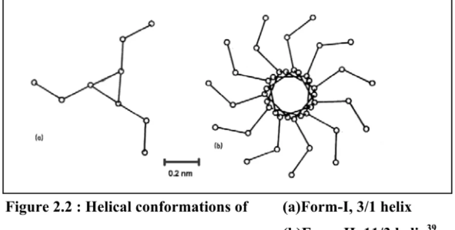
Form-II of isotactic polybutene-1 can be directly obtained by crystallization from melt at atmospheric pressure, from dilute solutions of certain solvents at certain temperatures,15,16,24, with annealing of Form-III and Form-I’ at certain temperatures24 and also by epitaxial crystallization.17 Crystallization on a substrate surface from the bulk is called epitaxial crystallization. Form-II is characterized by tetragonal unit cell with dimensions a=1.542 nm, b=2.105.12 Molecular chains with 11/3 helical conformations are packed to give 4P space group. Melting point of Form-II is around 118 oC at atmospheric pressure. Figure 2.2 shows schematically the helical conformations of Form-I and Form-II.
Figure 2.2 : Helical conformations of (a)Form-I, 3/1 helix (b)Form-II, 11/3 helix39
Form-III of isotactic polybutene-1 can be obtained by crystallization from dilute solutions of certain solvents at certain temperatures,15,16,19,24 by epitaxial crystallization17,19 and by polymerization at high temperatures up to 100 oC.2 Form-III is characterized by an orthorhombic unit cell with dimensions a=1.238, b=0.888, c(chain axis)=0.756nm.19 Molecular chains with 4/1 helical conformation are packed to give a P212121 space group. Form-III has a melting point around 95 oC at atmospheric pressure. Form-III is stable at room temperature but unstable at temperatures near its melting point. The annealing temperature determines whether
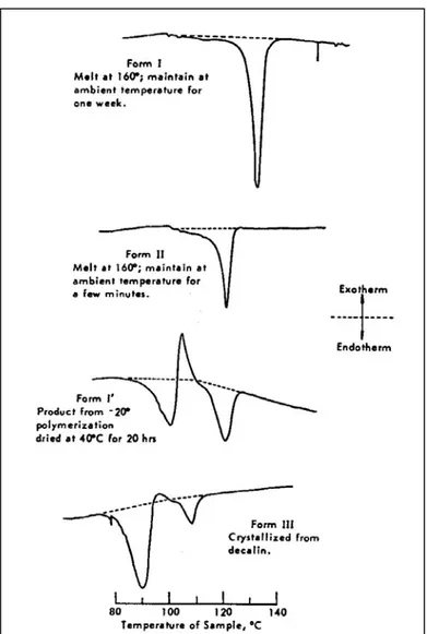
Figure 2.3: DSC thermograms of various polymorphs of iPB-111
Form-I’ of iPB-1 can be obtained by melt crystallization under high pressure13
or if shear is applied to a solidifying melt34, by crystallization from certain solvents at certain degrees24 and by epitaxial crystallization.18,20 Form-I’ can also be obtained by polymerization at low temperatures.11 Form-I’ is stable at room temperature but transforms into Form-II upon annealing near its melting point. Form-I’ has the same unit cell as Form-I except that molecular chains are untwinned. The Form-I’ has a melting point around 95 oC at atmospheric pressure. 2
The fifth polymorph, Form-II’ can only be obtained by crystallization under high pressure. Form-II’ is not stable and transforms into Form-I’ at room temperature and atmospheric pressure. 13
2.4 Form-II to Form-I Crystal Transformation
2.4.1 Introduction
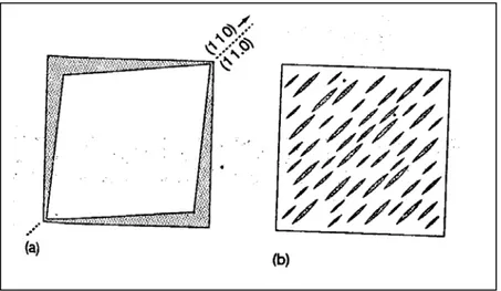
The figure 2.5 above summarizes the various crystal-crystal transformations of iPB-1.24 For the crystallization from solution, only an amyl acetate solution is considered for simplicity. The most important of these is the crystal transformation of Form-II into Form-I upon standing at room temperature and atmospheric pressure. This transformation is a solid state transformation. This transformation is heavily studied because of its commercial importance. Form-II spontaneously transforms into the more stable crystalline structure Form-I.2,23-30,32,33 In other words, moulded articles have Form-II crystal structure just after the moulding process. This crystal transformation is accompanied with the change of physical properties; increase of melting point, heat of fusion and density. However, the shape of the moulded objects does not change considerably. This transformation may cause crack formation.23 Cracks develop in the structure since the density increases. These cracks affect mechanical properties adversely. Figure 2.6 illustrates the development of cracks during this transformation. This transformation results in a increase in the length of a molecule of about 14% and a decrease in cross-section area of about 10%. 2
Figure 2.6 : (a)Shrinkage(shaded area) of square Form-II crystal upon conversion to Form-I when the indicated (110)I-(11.0)II plane is maintained in the transformation
(b)Development of cracks and elongated domains to accommodate this shrinkage when the overall crystal dimensions are constrained23
The application of macroscopic shears during processing as in the case of shear controlled orientation injection moulding (SCORIM) results in mouldings with completed Form-II to Form-I transformation. Therefore the development of possible crack formation at room temperature could be avoided.34,52
2.4.2 The Rate of Transformation From Form-II to Form-I
This transformation may take days to weeks depending on the conditions.23 Form-II completely transforms into Form-I in one week at room temperature and atmospheric pressure. The rate of this transition is affected by thermal history, temperature, mechanical deformation, pressure, orientation, x-ray radiation, molecular weight and tacticity, additives, blends, nucleating agents, and copolymerization. 2
The transformation of Form-II into Form-I is through a nucleation processs and follows the Avrami equation where Vx(t) is the volume fraction of the the Form-I
(transformed). 14,28,32
Vx(t) = 1 - exp ( - Ktn). Eq. 2.1
Here K is the rate constant and n is Avrami constant which depends on both form of nucleation and growth of the stable phase.
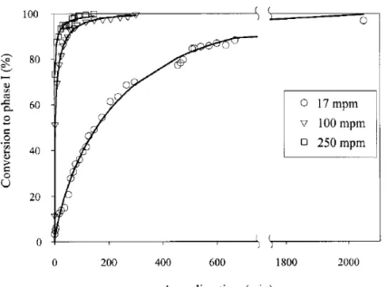
Figure 2.7 shows the overall conversion of Form-II to Form-I as a function of time for three different take up speed for iPB-1 fibers. Avrami type fits are shown in Figure 2.7 as solid lines. The change of overall crystallinity with time clearly fits to Avrami equation. As the take up speed is increased, orientation of molecular chains in the iPB-1 fibres increase. And as the molecular orientation increases, the rate of transformation from Form-II to Form-I increases. This is akin to what is observed for SCORIM moulded iPB-1as mentioned above.
Figure 2.7 : Percentage conversion to stable Form-I as a function of annealing time for different take up speeds. Avrami-type fits to data are shown as solid lines on the graph.32
This transformation is fastest at room temperature. The rate of transformation decreases as the temperature is increased or decreased. No transformation is observed at 100 oC or at dry ice temperatures.2,29 The transformation can be completed in a few seconds under hydrostatic pressures above 100 atm. The uniaxial stretching of the polymer also increases the rate of transformation sharply. It is considered that uniaxial stretching helps molecules to rearrange since transformation is accompanied with a decrease in the cross-section and an increase in the length of the molecule. The application of external stresses also increases the rate of transformation through increasing the rate of nucleation.2 The rate of the transformation is also affected by the thickness of the films. 25 In the absence of external stress, the rate of transformation decreases with decreasing film thickness. However, when external stresses are applied the relation is reverse. As the film thickness is decreased, the rate of transformation increases. In a study on the crystal growth rate of poly(ethylene oxide), a remarkable slowing down of the crystal growth for films with thicknesses less than approximately 100 nm was observed.54 For the poly(ethylene oxide) films with thicknesses over 200 nm, no change in the spherulite growth rate is observed.
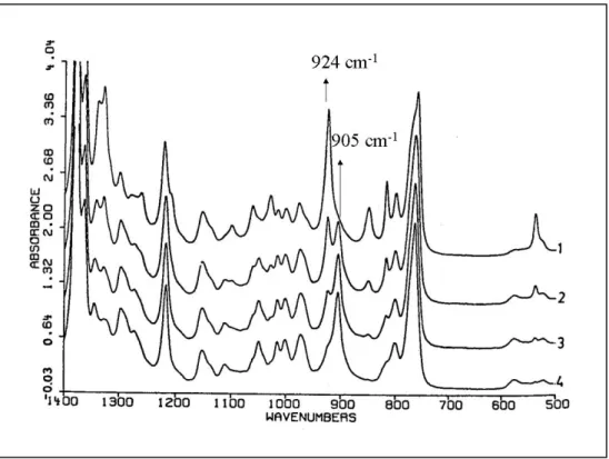
The rate of transformation can easily be followed by FT-IR spectroscopy.29 Form-II and Form-I have completely different spectra from 1500 to 450 cm-1. Figure 2.8 shows the FT-IR spectra of films of iPB-1 aged at room temperature for various
times. The sample aged for 15 minutes and the one aged for 1 year correspond to unstable Form-II and stable Form-I, respectively. The bands at 905 cm-1 and 924 cm-1 allow us to differentiate between these two forms of iPB-1. The one at 905 cm-1 is the characteristic band of Form-II and the one at 924 cm-1 is the characteristic band of Form-I.25 The half-life of this transformation can be determined with the ratio of IR extinction of these two peaks. Half-time is reached when the ratio of IR extinction of Form-I (924 cm-1) to IR extinction of Form-II (905 cm-1) equals approximately 1.5
Figure 2.8 : IR spectra of iPB-1, curve 1 = aged for 1 year, curve 2 = aged for 10 h, curve 3 = aged for 2 h, curve 4 = aged for 15 min25
2.5 Polymer Crystalllization
2.5.1 Introduction
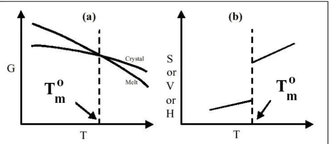
A crystal has lower free energy than liquid at temperatures below the thermodynamic melting point Tmo. 40 Figure 2.9 shows the change of thermodynamic variables at Tmo. The crystallization of polymers is associated with a negative Gibbs free energy. However, the arrangement of all chains requires a large negative entropy of activation. Below the glass transition temperature Tg, the energy of the chains is not enough to rearrange and this restricts the crystallization between Tg and Tm.37 It can be said that the crystallisation of polymers is kinetically rather than thermodynamically controlled. Polymers do not crystallize completely unlike oligomers.37 Entanglements of the chains prevents the formation of complete crystalline order. The exact nature of the polymer crystals is not known completely yet although there are a few models to explain the crystal structures of polymers.40
Figure 2.9 : General Behaviour of thermodynamic variables at the equilibrium melting temperature Tm∞ (a)Gibbs free energy (b) Entropy, Volume and Enthalpy 40
The first step of the crystallization is the formation of a stable nucleus. (nucleation). Nucleus is formed by the parallel ordering of the chains stimulated first by intramolecular forces and then stabilised by the secondary valence forces (long range order forces), which provides the packing of molecules into a three-dimensional ordered structure.37
Nucleation is followed by the growth of the crystal region. The size of the crystal increases as the new chains added to the crystalline region. Thermal
redispersion of the chains at the crystal-melt interface counteracts the growth of the crystal.37
The extended chain morphology, in which all the chains are parallel and the size of crystal equals the extended length of a chain, is considered as the equilibrium morphology for most polymers.36 However, the exact morphology of the polymer crystals depends on the crystallization conditions. We can classify the crystallization of polymers under three main groups: 36,40
I-Crystallization during polymerization
II-Strain induced crystallization
A-crystallization from solutions under strain B-crystallization from melts under strain
III-Crystallization under quiescent condition A-crystallization from quiescent solutions B-crystallization from quiescent melts
2.5.2 Crystallization during polymerization40
The crystal obtained during polymerization is not just a consequence of the change in physical state. The crystal is obtained during chemical reactions at the gas/solid or the solid/liquid interfaces. The mechanism of crystallization might be simultaneous polymerization and crystallization, or crystallization follows the polymerization. Macroscopic crystals can be obtained by crystallization during polymerization. The crystalline structure of the polymer is also affected by the polymerization conditions.13
2.5.3 Strain Induced Crystallization
2.5.3.1 Crystallisation from Solutions under Strain
When there is no external force, there is no preferred orientation of polymer chains (unoriented). However, if an external force is applied, the polymer chains are oriented and this orientation of chains ends up with a different crystal morphology.36 When a dilute polymer solution (1 %) is stirred during crystallization, shish-kebabs may form. The backbone, shish, is composed of extended chains and kebabs grow epitaxially on this backbone.36
2.5.3.2 Crystallisation from Melts under Strain
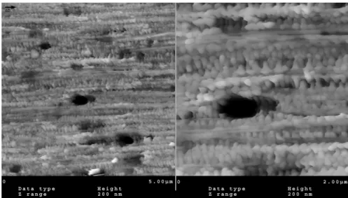
Similar to the solution case, the applied force results in the orientation of polymers. By the application of shear to a solidifying melt, shish-kebabs can be formed. The mechanical properties of the articles can be improved by the formation of shish-kebab morphology.34 Figure 2.10 shows the AFM image of a SCORIM moulded polybutene-1. The interlocking shish-kebabs can be clearly seen in this image.
Figure 2.10 :AFM image of the shear region of iPB-1 processes by SCORIM. The injection direction is identified with an arrow34
Application of stress to an amorphous or a semi-crystalline polymer between Tm and Tg is likely to increase the crystallinity of polymers since the polymer chains
are oriented in the direction of applied stress. The process known as cold-drawing is done between this temperature range.
2.5.4 Crystallisation under Quiescent Condition
2.5.4.1 Crystallisation from Quiescent Solutions
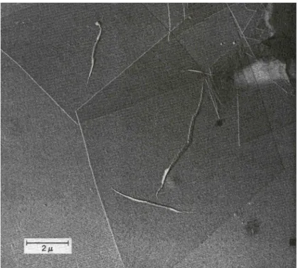
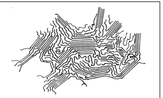
A single crystal of polymers from solution was first reported in 1953. Before, it was believed that single crystals could not be produced from solutions because of molecular entanglements. Later, single crystals of so many polymers obtained from their solutions. The single crystal of polyethylene in shown in Figure 2.11. Pleats in the crystal may occur often.36
Figure 2.11 :Electron micrograph of linear polyethylene grown from a solution of perchloroethylene36
The single crystals of all polymers have the same geometry, thin and flat platelets. The thickness of these platelike structures is around 10 nm and the lateral
regularity of the crystals are determined by the crystallization conditions like temperature and solvent type.36
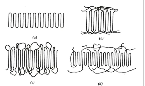
The electron diffraction measurements demonstrated that that polymer chains are aligned normal or nearly normal to the plane of the lamellae. Since the length of a polymer molecule is generally much larger than the thickness of the lamellae, it can be concluded that the chains are folded during the formation of lamellae. Different models have been proposed to explain the nature of the folding surface as shown in Figure 2.1236
Figure 2.12 : Schematic two dimensional representations of models of the the fold surface (a)sharp folds (b) “switchboard” model, (c) loose loops with adjacent reentry
(d) a combination of several features.36
The structural and kinetic evidences show both there is a regular folding of chains with immediate reentry into the crystal and also a considerable molecular disorder exists in polymer single crystals. The extent of the disorder is too large that it can not be considered as a result of intercrystalline defects and implies existence of some amorphous region at the fold surface. The “switchboard” and “adjacent entry with loose loops” models have been suggested to explain the existence of the amorphous region.36
In addition to lamellae, the crystallization from the solution may result in complex structures similar to those found in polymers crystallized from the melt.
Formation of sheaflike arrays similar to spherulites, dendritic growths, clusters of hollow pyramids, spiral growths, dislocation networks are also reported.36
2.5.4.2 Crystallization from Quiescent Melts
2.5.4.2.1 Fringed Micelle Model
Bragg reflections of polymers are broad and diffuse unlike that of the well-developed single crystals. This broadening is assumed to be the result of small crystallite size but not because of the imperfections of the crystal. Therefore, the size of these crystals is in the order of the 10 nm, when calculated considering the broadening of the lattice. Since the chains are much longer than this distance, the fringed micelle model has been suggested which states that chains contributes to several crystalline and amorphous regions.36
Figure 2.13 : Fringed micelle model of the crystalline-amorphous structure of polymers36
The fringed micelle model is quite simple and successful for the explanation of good mechanical properties as a result of combined crystal and amorphous layers and simple interpretation of degree of crystallinity. However this model can not explain the growth of spherically symmetrical structures called spherulites. This was overcome by the later discovery of polymer single crystals with lamellar structures including chain folding. Spherulites are shown to be complex structures of lamellae. Therefore it was concluded that the fringed micelle model is inaccurate for the general
occurring in the crystallization of polymers like gelation during polymerization and crystallization during rapid cooling/quenching.40
2.5.4.2.2 Spherulites
Spherulites are spherical aggregates of lamellae’s with sizes ranging from submicroscopic sizes to milimeters.39 Spherulites are observed as circular birefringent areas possessing a dark Maltese cross pattern. A schematic of Maltese cross pattern and a spherulite of iPB-1 are shown in Figure 2.14. The orientation of Maltese cross depends on the direction of polarizer and analyser. As the polarizer are rotated, the maltese cross also rotates.
Figure 2.14 : A schematic diagram of ordering of the indicatrices in a spherulite and the resulting Maltese cross extinction pattern and a micrograph of spherulite of iPB-1.39 The single spherulite
on the right is taken from the real time movies of spherulitic growth investigated in this thesis.
A schematic of structure of a spherulite is shown in Figure 2.15. The spherulites consists of fibrils and fibrils consists of lamellae radiating outward.37 The chain folding direction is transverse to the radial direction.39 Between the lamellae there exist amorphous regions and tie chains that connects the lamellae.37
Figure 2.15 : A Schematic diagram of fully developed spherulite grown from the melt.37
In Figure 2.16, the right side is the electron micrograph of a spherulite of iPS at an early stage of development. The central part is composed of parallel layers. As the spherulite grows, these layers become curved and at the end the sphere forms. Splaying and branching are necessary since the surface area increases as the spherulite grows.39
Figure 2.16 : Left :Electron micrograph of central sheaf-like part observed at an early stage of development of a spherulite of iPS. Right : schematic of branching and splaying in the fully developed spherulite39
If the refractive index along the transverse direction is greater than that of along the radial direction, spherulite is called as negatively birefringent and when the
2.5.4.2.3 Nucleation
There are two main groups of nucleation : heterogeneous and homogeneous. Heterogeneous nucleation is due to foreign particles. These foreign particles (or surfaces) must reduce the boundary surface energy, must have a melting point above that of the polymer and must be insoluble in the polymer melt.38 Nucleating agents increase the nucleation rate but does not influence the spherulitic growth rate.37
Homogeneous nucleation is the nucleation of the polymer without a second surface or pre-existing nuclei. Homogeneous nucleation can be thermal or athermal. If the random fluctuations of chains result in crystal-like regions (embryos), these are called thermal nucleus.38 These embryos are not stable above the melting point and no crystallization begins. Below the melting point, the critical size of the nucleus depends on the temperature. This is shown in Figure 2.17. As the temperature increases, the critical size of the nucleus also increases. Above this critical size, the formation of nucleus is favoured. Below this size, the embryo is not stable and no nucleation takes place. 38
Figure 2.17 : Free energy of crystal nuclei formation as a function of temperature.38
The following equation describes the rate of thermal nucleus formation where η(T) is the viscosity of material at temperature T, ∆Gmax is the activation energy for nucleus formation and No is normalization factor:38
RT o max
(T)
T
N
N
=
e
∆Gη
&
&
Eq. 2.2The thermal nucleation rate increases as the temperature decreases since ∆Gmax decreases. As the temperature decreases more, the rate of thermal nucleation first goes through a maximum and then decreases as the temperature gets close to Tg. The change of primary and secondary nucleus formation rates as a function of crystallization temperature is shown in Figure 2.18 As the temperature decreases, the changes in the viscosity term, T/η(T), is responsible for the decrease of the nucleation rate.38 As the viscosity increases, the possibility of chains to form primary nucleus through random molecular motion of chains decreases since the kinetic energy of the chains decreases.37
The molecular weight of the polymer affects the nucleation rate through the viscosity of the polymer melt.37 As the molecular weight of the polymer increased, the viscosity increases and final result is the decrease of the rate of thermal nucleation.
As for the athermal nucleation, when the temperature falls rapidly, a crystal embryo becomes stable nucleus since the critical size decreases as the temperature is decreased. Therefore, with a rapid drop in temperature, the athermal nucleations take place at the same time and this give rise to the same spherulite size whereas thermal nuclei result in different sized spherulites since nucleation takes place at different times.
Figure 2.18: Primary and secondary nucleus formation rates as a function of crystallisation temperature.38
2.5.5 Kinetics of Lateral Crystal Growth
The growth of the crystal occurs by secondary and tertiary nucleations on the crystal surface.38 The activation energy of secondary and tertiary nucleations is smaller than the primary nucleation.38 This is due to the new interfacial area formed as a result of growth. The interfacial area decreases as the order of nucleation increases. Therefore, the maximum of the secondary nucleation rate is at higher temperatures than the maximum of the primary nucleation rate as shown in Figure 2.18. As a result, the size and number of the crystals formed depends on the crystallization temperature Tc. Provided that a constant degree of crystallization, at low temperatures a high number of small crystals form. Whereas at high temperatures, a small number of big crystals forms. 38
2.5.5.1 Lauritzen-Hoffman Secondary Nucleation Theory
Lauritzen-Hoffmann secondary nucleation theory explains the crystallization kinetics (effect of temperature on crystal growth rate) of linear flexible polymers which are crystallized from melt into a lamellae by chain folding. The theory is also applied for the crystallization kinetic of more rigid polymer like PEEK.40
The theory accounts for a wide range of experimental observations like the variation of lamellar thickness by degree of supercooling, break in temperature dependence of growth rate, the origin of σ and σe (respectively lateral surface interfacial free energy and fold surface interfacial free energy), the effect of adjacent (tight folding) and non-adjacent events (tie chains, loose folds, cilia). However, the theory can not address completely the primary nucleation (thus the bulk crystallization kinetics), how a lamellae develops from a primary nucleus, how the lamellar branching give rise to spherulites, banding in spherulites, and quantified estimation of degree of crystallinity.36,40
Preliminary assumption of the theory is chain folding. The lamellar formation is kinetically controlled and results in a metastable crystal. The thermodynamically stable form is extended chain crystal. Increase of the melting point upon extended annealing shows that formed lamellae is not yet a stable product.41 The treatment in
the theory starts with the deposition of first stem and later stepwise deposition of subsequent stems are considered.40 A stem is the portion of chain occupying the length lg*, the fold thickness of lamella. (see Figure 2.19).
The rate constants for the deposition of the first step, where Ao is for forward
and B1 is backward reaction rates :40,44,8
) 2 exp( c f o o o o kT G l b a l b A =β − σ +φ ∆ Eq. 2.3 ), ) 1 ( exp( 1 c f o o kT G l b a B =β − −φ ∆ Eq. 2.4
where β : retardation factor related to the transport machanism of the chain to the nucleation site,
σ : lateral surface interfacial free energy, σe : fold surface interfacial free energy,
o
a : width of the crystalline stem,
o
b : thickness of the crystalline stem, l : length of the crystalline stem, ∆Gf : free energy per unit volume,
Φ : Fraction of ∆Gf apportioned to the forward reaction.
k : Boltzmann constant
and for the subsequent steps the rate constants for the forward and backward reaction are :40,44 ) 2 exp( c f o o e o kT G l b a l b A=β − σ +φ ∆ Eq. 2.5 B=B1 Eq. 2.6
From the steady state flux calculations, the rate of stem deposition can be expressed as :40,44
where No is the number of initial stems which can crystallize and in front of the
substrate.
The parameters leading up to crystal growth rate ‘G’ are the surface nucleation rate i and substrate completion rate g. The rate of stem deposition equals :40,44
∫
∞ ∆ = f e G u l dl l S l a n l i / 2 0 ) ( σ , Eq. 2.8where nl is the number of stems with length a in a substrate length L (no la =L) and lo u
is the monomer length (projected length per monomer unit). Then,40,44
∆ − ∆ + − = c f e o f o c o c u o l o kT G b G b kT b kT l a n B N i σ σ σ σ 4 exp 2 2 Eq. 2.9
and the rate of substrate completion equals g =ao(A−B). Then,
− ∆ − − = c f o o c e o o u o l o o kT G l b a kT b a l a n B N a
g βexp exp 2 σ exp Eq. 2.10
The nature of the relation of G on i and g depends on the relative rates of i and g. These are shown in Figure 2.19 40 The rate of crystal growth G corresponding to different regimes of growth can be calculated from the Figure 2.19 and results are shown in the Figure 2.19 as well.
The retardation factor β, which is related to the transport mechanism of the chain to the nucleation site, can be described as :40
− − = ∞) ( exp * T T R U J β Eq. 2.11
where U* is the activation energy for chain transfer, T∞ is the temperature at which all motion associated with viscous flow stops and the polymer is like a solid, R is gas
constant and J is a factor, which is given as below in a recent version of the L-H crystallization theory :40 = h kT n J κ Eq. 2.12
where h is Planck’s constant, κ is a numerical constant evaluated from the monomeric friction constant and the ‘
h kT
’ is a frequency factor in events per second and n is the number of repeat units.
Figure 2.19 : Scheme illustrating the rates of stem deposition during three different regimes of crystallization, ‘i’ represents the rate of stem nucleation whereas ‘g’ represents the rate of substrate completion40
When we substitute these relations for the ‘i’ and ‘g’ in the equations for the growth rate G for different regimes as shown in Figure 2.19, the growth rate G for these regimes equals :40
Where, ∆ + − = f o u i b ab G kT b kT l J b N G 0 0 0 0 0 0 σ 2 σ Eq. 2.16
and KgI = KgIII =2KgII
f o m e H k T b ∆ =4 0σσ Eq. 2.17 2.5.5.2 Regimes of Growth
In Regime –I, the rate of substrate completion is much bigger than the rate of stem nucleation and no new nucleus forms before the first layer is completely filled.40 Many molecules may be necessary to complete the layer. In this regime, adjacent reentry of molecules takes place and deposition rate is highly affected by the temperature.41
In Regime-II, the rates substrate completion and stem deposition has the same order and new nuclei can form before the previous layer is completely filled. Larger undercooling is necessary to reach Regime-II in comparison with the Regime-I. Also in this regime, adjacent reentry of the molecules is assumed.40,41
In Regime-III, the rate of stem nucleation is much bigger than the rate of substrate completion and as a result the high number of nuclei form on the existing layers before the completion of the layer. The crystallization rate is very high and supercooling is higher than those of Regime-I and Regime-II. In this regime, chains do not undergo adjacent reentry. The chains fold via a type of ‘switchboard model’ and they have only a few folds before entering the amorphous phase and free to reenter the same lamellae.40,41
2.5.5.3 Spherulite Growth Rate vs Temperature
The radial growth of spherulite is usually linear at constant temperature.41 The growth rate of spherulites approaches zero at Tm and Tg, and is maximum around Tmax=0.5(Tg+Tm).41 But measurable rates of spherulite growth rate is generally
restricted between Tg+30 K and Tm-10K as a result of thermal motion of polymer chains is conducive to the formation of stable regions between these temperatures.37 The radial growth rate r of the isotactic polystyrene as a function of the crystallization temperature is shown in Figure 2.20. The radial growth rate first increases and reaches a maximum then falls as the crystallization temperature increases.
Figure 2.20 : Radial growth rate of spherulites of iPS versus crystallization temperature37
Spherulite growth occurs by the simultaneous two-dimensional crystallization of the constituting crystallites.36,39 Therefore, spherulite growth rate can be used instead of the crystal growth rate G. G0I, G0II and G0III in the equations 2.13, 2.14 and
2.15, respectively, show little dependence on the temperature. Thus they can be treated as constants.45 This assumption enables us to obtain the K0I , K0II ,K0III and G0i
values with a plot of LnG + U*/R(Tc-T∞) vs 1/T∆Tc.40 These plots are called L-H
plots. The common used values for U* and T∞ are 1500 cal/mol and Tg-30K for most
polymers, respectively.40,44 Figure 2.21 shows a typical growth rate data and corresponding L-H plot. All the regime transitions may not be observed for every polymer.40
Figure 2.21 : A Schematic diagram illustrating the conversion of growth rate data to L-H plot.40
From the growth constants KgI = KgIII =2KgII
f m e H k T b ∆
=4 0σσ , the product of the
fold and lateral surface energiesσσ can be found.e 40 Then since the lateral surface free energy equals:44 f H b a ∆ = 1/2 0 0 ) ( 1 . 0 σ , Eq. 2.18
we can determine the value of the fold surface free energy σ when e a0, b0 are known.44
2.5.6 Bulk Crystallisation Kinetics and the Avrami Equation
Change of overall crystallinity of the sample over time can be followed by DSC, X-ray diffractometry and dilatometry.41 When the nucleation of spherulites is assumed to be a Poisson process41, that is the random distribution of nuclei’s in the polymer melt, the change of overall crystallinity of the the polymer can be described by the Avrami Equation where Q shows the crystalline fraction40,41
Q=1-exp(-Ktn) Eq. 2.19
The parameters K is usually called bulk crystallization constant and n is called Avrami exponent. The bulk crystallization constant K depends on the geometry of the growing crystalline entities and amount and type of nucleation. The Avrami exponent
n depends on the geometry and type of the nucleation but does not depend on the
amount of the nucleation.40
The Avrami equation is simply a mathematical solution of a crystallization model. Here are some examples :40,41
i) N 2-dimensional discs growing with a constant rate G and nucleated at the same time :
Q=1-exp(-π G2Nt2)
Here K= π G2N and n=2
ii) 2-dimensional discs growing with a constant rate G and forming at a rate N’
Q=1-exp(-(π /3) G3N’t3)
Here K= (π /3)G3N’ and n=3
In these examples, the growth G is assumed to be only the result of the nucleation at the growth surfaces of the discs. But when other factors like transport of the heat or molecules to the interface, are the rate determining step of the crystal growth, the growth rate can be expressed as G=(2K/t)1/2 where K is the diffusion constant. The crystal growth G is generally constant. As a result, the Avrami exponent may also get some half-integer values. 40,42
Table 2.2 shows various Avrami exponent values corresponding to different crystal geometries, nucleation types and rate determining steps for the crystal growth rate G. In this examples with the Avrami coefficient is either an integer or an half-integer.However in experimental studies, different values are aften reported for n as a result of Avrami analysis.40,41 This may be as a result of the assumptions in the derivation of Avrami equation. Therefore, the microscopical investigations of the samples are necessary before any interpretation of the Avrami exponent n.40
Avrami Exponent Crystal Geometry Nucleation Type Rate Determination
0.5 Rod Athermal Diffusion
1 Rod Athermal Nucleation
1.5 Rod Thermal Diffusion
2 Rod Thermal Nucleation
1 Disc Athermal Diffusion
2 Disc Athermal Nucleation
2 Disc Thermal Diffusion
3 Disc Thermal Nucleation
1.5 Sphere Athermal Diffusion
2.5 Sphere Thermal Diffusion
3 Sphere Athermal Nucleation
4 Sphere Thermal Nucleation
Table 2.2 : Avrami Exponents for various geometries, nucleation types, and rate determining step for crystal growth G40
2.6 Supermolecular Structure of iPB-1
Spherulites form when iPB-1 is crystallized from the quiescent melt14, 43-49 and single crystals are obtained upon crystallization from dilute solutions.15,16,19,23-25,50 Shish-kebab morphology is also observed when macroscopic shear is applied to a solidifying melt.34-52
Monasse and Haudin44 have studied the morhologies and regimes of growth of two different grades of iPB-1with different molecular weights. They have observed negatively birefringent spherulites from 40 oC to 110 oC. Maltese cross of iPB-1 spherulites blurs as the temperature is increased. Above 90 oC, they have observed that the shape of crystallite entities deviates from sphere. Polyhedrons and squares were seen above 90 oC. The rate of growth of spherulites were linear and bigger spherulites (crystal entities) formed at higher temperatures. Birefringence of the spherulites also decreases as the temperature is increased. With L-H plots, they have managed to observe all regime transitions of iPB-1. In their work, it was shown that the radial growth rate increases with increasing molecular weight for the two different molecular weight iPB-1 investigated.
Icenogle et.al.51 have investigated the effect of a wide range of nucleating agents on the crystallization rate of polybutene-1. Most of the additives (Phthalimide, Nylon 11, Polywax 850, Polywax 2000, Alizarin, Quinalizarin e.t.c) enhances the crystallization rate through increasing the number of heterogeneous nucleation. However, some additives decrease crystallization rate. (Anthrone, 9-methyl antharacene, Antharecene, 9-10 dihydro antharacene). The additives decreasing crystallization rate probably acts as a diluent.51
Cortazar and Guzman47 have investigated the effect of molecular weight on the crystallization kinetics of iPB-1. They have obtained fractions with narrow molecular weight distribution. The half-time of the crystallization decreased with increasing molecular weight. In other words, crystallization rate were shown to
surface free energy σe with L-H plots and the fold surface free energy σe were also shown to increase with increasing molecular weight.
Spherulite growth rate of iPB-1 has also been measured in other studies.14,44-48 Hot stage microscopy were usually employed to measure the spherulite growth rate. Huang et. al.46 have used a thermal gradient setup that enables to measure the spherulite growth rate for all temperatures at once.
Hot stage microscopy is quite useful for small rates of crystallization. However, when the crystallization takes place in short time interval, hot stage microscopy can not be used since the supercooling rate is small. For this purpose, a liquid medium at Tc can be used for crystallization. 53
2.7 Applications of Isotactic Polybutene-1
iPB-1 has en excellent creep resistance. Figure 2.22 shows the creep behaviours of some polyolefins compared with iPB-1.3 Therefore, iPB-1 is an ideal material where creep resistance is the key point. 80 % of the PB-1 is used in pipes.2 Besides, iPB-1 is used in films and sheets, molding, composites, cables, fibers, and blends.
Figure-2.22 : Creep Behaviour of polyolefin resins compared to PB-1. 3
CHAPTER-3. EXPERIMENTAL PROCEDURE AND THE DESRIPTION OF THE CRYSTALLIZATION CALCULATIONS
3.1 Materials
Four different grades of commercial homopolymers of polybutene-1 were investigated. These materials have been suplied by Shell Research SA (Louvain-la-Neuve, Belgium). These materials are now available from Basell Inc., which is a merger of Shell’s and BASF’s polyolefins businesses. These grades are isotactic and semi-crystalline exhibiting high creep resistance and environmental stress crack resistance even at elevated temperatures. These are known as PB0110, PB0300, PB0400, and PB0800. Tables 3.1 and 3.2 summarize the densities, the melt flow indices (MFI), the molecular weights and the polydispersities of these four grades investigated. Molecular weights were determined at the Shell Research SA laboratory in Louvain-la-Neuve. Gel permeation chromatography (GPC) was employed to determine the molecular weights. Only PB0110 contains nucleating agents but all contains a heat stabilizer. They are developed for different applications ranging from injection moulding (PB0110, PB0300, PB0400), extrusion (PB0110), blow moulding (PB0110) to adhesives and sealants (PB0800).
Grade General Nucleating
Agents Density MFI (190
0C/2.16 kg) ASTM D1238 PB0110 Isotactic Homopolymer Yes 0.915 sp gr 23/23 0C (ASTM D792) 0.4 g/10 min PB0300 Isotactic Homopolymer No 0.915 sp gr 23/23 0C (ASTM D792) 4 g/10 min PB0400 Isotactic Homopolymer No 0.915 sp gr 23/23 0C (ASTM D792) 20 g/10 min PB0800 Isotactic Homopolymer No 0.915 g/cm 3 (ASTM D1505) 200 g/10 min
Table 3.1 : The densities and the melt flow indices (MFI) of the investigated PB grades3
Grade Mn Mw Mz Polydispersity PB0110 128700 121900 854800 847500 2497400 2449500 6.6 7.0 PB0300 98600 97500 391800 405000 1038000 981800 4.0 4.2 PB0400 81300 82200 246400 241800 508600 502400 3.0 2.9 PB0800 71000 194900 439500 2.7
3.2 DSC Characterization
A Setaram LabsysTM DSC12 was used for measuring DSC thermograms of polymer pellets as received. The pellets weigh from 15 mg to 35 mg. They were sealed in aluminium pans. A heating rate of 2 oC / min. was applied. Three repeats were carried out for each sample. The melting peaks and the enthalpy of fusion were determined from the thermograms. Crystallinity of the samples determined by enthalpy of fusion of sample divided by the enthalpy of fusion of the Form-I. (Table 3.3) Polymer pellets were assumed to include only Form-I crystals. The enthalpy of fusion of the samples were determined with an Indium reference. The ratio of the integral area per miligram of the sample divided to that of the Indium reference were calculated then multiplied with the enthalpy of fusion of Indium reference.
3.3 FT-IR Measurements
The FTIR spectra were recorded on a BOMEM MB 102 FTIR spectrometer with a resolution of 4 cm-1 and 32 scans. 6.1 mg of PB0110 sample was melted between two microscope slides and left for cooling for a few minutes at room temperature and then transferred to the sample holder of the spectrometer. FTIR spectra has been taken after 15min, 30 min, 45 min, 60 min, 90 min, 2h, 3h, 4h, 6h, 12h, and 10days.
3.4 Spherulite Growth Rate Measurements
3.4.1 Microtomy
First 100mmX100mmx8mm plates were compression moulded in the Department of Chemistry, METU (Ankara). The melt temperature used was 200 oC. Following the compression moulding, a section with dimensions shown in Figure 3.1 was cut from the mouldings for efficient and secure clamping in microtomy. A Shandon Finesse 325 rotary microtome was used to cut thin sections of approximately 10 µm. A disposable steel knife and a 35o of included angle was used in microtomy. The knife and the specimen were maintained at room temperature. The length of the thin sections varied from 4 mm to 10 mm. A soft brush was used to retrieve the sections before they curled and then the samples were sandwiched between two glass
slides with the help of the brush. The aim of using thin films in the experiments are to provide the isothermal cooling of the sample and restrict the spherulite growth in 2-dimensions. Thin films were used so as to provide the isothermal heating of the sample.
3.4.2 Crystallization Experiments
After microtomy, the samples were melted at 200 0C ±10 0C on a hot plate. (Cole-Parmer, VELA, 2000) After keeping the samples for one-two minutes in molten state, they were pressed with the help of a microscope cover slide to remove the air bubbles and obtain a smooth thin film. The samples were kept at this temperature for another 3 minutes to erase any crystallization memory and any flow effects that might have been caused by the cover slide. Then samples were quickly moved to the spherulite growth rate set-up. The stress applied on the samples resulted in films with thicknesses 7±2 µm. The thicknesses of the films calculated with respect to the change of the area of the film.
3.4.3 Spherulite Growth Rate (SGR) Set-up
The Schematic of the spherulite growth rate set-up is shown in Figure 3.2. The SGR setup was placed on the microscope and the growth of spherulites were recorded as a real time movie with the help of a JVC TK01085E CCD camera and a
Parmer J-type thermocouple. The crystallization medium was ethylene glycol to provide an efficient cooling of the sample and a good heat transfer. The Figures 3.3 and 3.4 was taken during the experiment. Figure 3.3 shows the set-up, the microscope and the PC. The pictures were taken with a Sony DSC F505V digital camera.
Figure 3.2 : Schematic diagram of SGR set-up
Ethylene glycol is suitable in this study because it is optically inactive and has a high viscosity that prevents wave formation in the bath, which may disturb the image. Water was also tried as a crystallization medium but waves formed on the surface of water due to small vibrations of the set-up preventing the imaging.
Thermocouple of the temperature controller was held very close to the sample holder in the set-up as shown in the Figure 3.4. Even though the temperature difference between any two points might be as high as 3 oC, the difference between the center of the sample holder and thermocouple was determined to be 0.5 oC.
The deviation of the temperature from the set temperature was ±1 oC. In fact the deviation was around ±0.2 oC when the set-up was kept still. However, since the set-up was moved to see the different regions of the film, the deviation was increased up to ±1 oC.
Figure 3.3 : Close-up picture of the SGR set-up
The function of the step-down transformer is to decrease the voltage so that power of the resistance decreases. It is necessary because if the power is too large, the liquid may heat up too fast preventing the temperature controller from operating properly.
3.5 The Measurement of Spherulite Growth Rate
Still pictures were obtained from the real-time growth movies of the spherulites and a picture of the graticule with the same resolution and size. Adobe Photoshop 5.0 was used in analysing the still images. The measure tool of the software was used to determine the spherulite size and therefore the spherulite growth rate. Adobe Photoshop Measure tool gives a distance ‘D’ in cm’s if the picture is printed without resizing. This enables us to measure the size of the spherulites provided that they have the same resolution and size.
Figure 3.6 : Micrographs of iPB-1 thin films crystallized at 70 oC. The micrograph on the right is
for crystallization time = 100 s and the one the right is for crystallization time = 200 s
From Figure 3.5,
4.29 D = 1000 µm => 1 D = 1000/4.29, 1 D = 233.1 µm, then from Figure 3.6 SGR = rf-ri/ ∆t = (0.60 – 0.53/2) x 233.1 µm / (200-100) s, =>
SGR= 0.78 µm / s
Figure 3.5 :Micrograph of the Graticule with length 1 mm and 100 divisions.