1
KADIR HAS UNIVERSITY
GRADUATE SCHOOL OF SCIENCE AND ENGINEERING
QUALITY OF SERVICE CONSTRAINED SCHEDULING FOR MASSIVE
M2M COMMUNICATIONS IN FUTURE CELLULAR NETWORKS
MUHAMMAD ABDUL MOHEMINE
3 Muha mm ad Abdul Mohe mi ne (M.S) The sis Apr il 20 18 S tudent’ s F ull Na me P h.D. (or M.S . or M.A .) The sis 20 11
4
QUALITY OF SERVICE CONSTRAINED SCHEDULING
FOR MASSIVE M2M COMMUNICATIONS IN FUTURE
CELLULAR NETWORKS
MUHAMMAD ABDUL MOHEMINE
MASTER’S THESIS
Submitted to the Graduate School of Science and Engineering of Kadir Has University in partial fulfillment of the requirements for the degree of Master’s in the Program of
Electronics Engineering.
ISTANBUL, APRIL, 2018 APPENDIX B
i
DECLARATION OF RESEARCH ETHICS / METHODS OF DISSEMINATION
I, MUHAMMAD ABDUL MOHEMINE, hereby declare that;
• This Master’s Thesis is my own original work and that due references have been appropriately provided on all supporting literature and resources;
• This Master’s Thesis contains no material that has been submitted or accepted for a degree or diploma in any other educational institution;
• I have followed “Kadir Has University Academic Ethics Principles” prepared in accordance with the “The Council of Higher Education’s Ethical Conduct Principles” In addition, I understand that any false claim in respect of this work will result in disciplinary action in accordance with University regulations.
Furthermore, both printed and electronic copies of my work will be kept in Kadir Has Information Center under the following condition as indicated below (SELECT ONLY ONE, DELETE THE OTHER TWO):
The full content of my thesis/project will be accessible from everywhere by all means. The full content of my thesis/project will be accessible only within the campus of Kadir Has University.
The full content of my thesis/project will not be accessible for ---- years. If no extension is required by the end of this period, the full content of my thesis/project will be automatically accessible from everywhere by all means.
MUHAMMAD ABDUL MOHEMINE __________________________ DATE AND SIGNATURE
ii
Table of Contents
ABSTRACT ... iv ÖZET ... v ACKNOWLEDGEMENTS ... vi DEDICATION ... vi LIST OF TABLES ... ix LIST OF FIGURES ... x 1 INTRODUCTION ... 1 1.1 Overview ... 1 1.2 Literature Review ... 2 1.3 Thesis Contribution ... 3 1.4 Thesis Outline ... 3 2 PRELIMINARIES ... 5 2.1 TYPEES OF MTC ... 5 2.1.1 mMTC ... 5 2.1.2 uMTC ... 6 2.2 REQUIREMENT OF mMTC DEVICES ... 6 2.3 M2M COMMUNICATION SUPPORTED BY 3GPP ... 62.3.1 M2M devices communicating with one or more M2M servers ... 6
2.3.2 M2M devices communicating with other M2M devices without intermediate M2M servers ... 7
2.4 RADIO RESOURCES ALLOCATION WITH QoS GUARANTEES ... 8
1.2.1 Grouping based radio resources management ... 8
2.4.1 Clustering based radio resources management ... 10
3 WAVE FORM CANDIDATE ... 12
3.1 OFDM (Orthogonal Frequency division multiplexing) ... 12
3.1.1 Limitation of OFDM ... 15
3.2 FBMC Filter Bank Multi Carrier ... 16
3.2.1 Disadvantages of FBMC ... 17
3.2.2 Advantages of FBMC ... 18
3.3 UFMC Universal Filter Multi-Carrier / Filtered OFDM ... 18
3.3.1 Advantages of UFMC ... 19
iii
4 FLEXIBLE FRAME ARCHITECTURE ... 21
4.1 Available spectrum ... 21
4.2 Time-frequency Multiplexing of users for 5G ... 22
4.2.1 TTI size ... 22
4.3 Subcarrier spacing ... 24
5 M2M RESOURCES ALLOCATION ALGORITHM ... 28
5.1 System Model ... 28
5.2 Details of optimization problem ... 30
5.2.1 Constraints of Problem ... 30
5.3 Optimization problem ... 30
5.4 NP-Hardness of Optimization Problem ... 31
5.5 Minimum Bands First-Fit Allocation Algorithm... 31
5.6 Description of Algorithm... 32
5.7 Algorithm Example ... 34
5.7.1 Algorithm Matlab an Example ... 35
5.8 Performance Evaluation ... 37
5.9 Scheduling Performance ... 39
5.10 Conclusion ... 42
iv
QUALITY OF SERVICE CONSTRAINED SCHEDULING FOR MASSIVE M2M COMMUNICATIONS IN FUTURE CELLULAR NETWORKS
ABSTRACT
Radio resource allocation for massive M2M communications is one of the key problems in next generation cellular networks. Satisfying strict and very diverse quality-of-service requirements increases the hardness of this problem. In this thesis, flexible scheduling problem for massive M2M communications is solved considering the physical layer architecture of 5G cellular networks. First, envisioned physical layer architectures and waveforms proposed for 5G are investigated and a physical layer architecture model that will allow flexible resource allocation is proposed. Then, a flexible radio resource allocation algorithm is proposed based on this model. The performance of the algorithm is shown through extensive simulations.
Keywords: 5G cellular networks, M2M communications, radio resource allocation, flexible physical layer..
v
QUALITY OF SERVICE CONSTRAINED SCHEDULING FOR MASSIVE M2M COMMUNICATIONS IN FUTURE CELLULAR NETWORKS
ÖZET
Büyük çapta M2M haberleşme için radyo kaynak dağıtımı gelecek nesil hücresel ağlarda anahtar problemlerinden biridir. Katı ve çok değişken servis kalitesi gerekliliklerinin sağlanması bu problemin zorluk seviyesini artırmaktadır. Bu tezde, büyük çaplı M2M haberleşmesi için esnek çizelgeleme problemi 5G hücresel ağların fiziksel katman yapısı da göz önüne alınarak çözümlenmektedir. İlk olarak, 5G için önerilen fiziksel katman yapıları ve dalga formları incelenmekte ve esnek kaynak dağıtımına imkan sağlayacak bir fiziksel katman yapısı modeli önerilmektedir. Daha sonra, bu modeli temel alan esnek radyo kaynak dağıtım algoritması öne sürülmektedir. Önerilen algoritmanın performansı kapsamlı simülasyonlarla gösterilmektedir.
Anahtar Sözcükler: 5G hücresel ağlar, Makineler-Arası-İletişim, radyo kaynak dağıtımı, esnek fiziksel katman.
vi
ACKNOWLEDGEMENTS
Without the existence of my being, no task could have been possible to accomplish for me in this mortal world. I am thankful to Allah Almighty,
This space of my thesis I will be given to thank my adviser, Dr. Yalcin Sadi , for his precious support and very helpful conversations throughout in my research endeavor. This dissertation would not have been completed without the help, guidance, assistance and countless pieces of advice of my Adviser Dr. Yalcin Sadi. He, out of his rather busy schedule, who give me time whenever I had any issue in my research work and put his best to make this effort a success. It is only because of his insight, enthusiasm, and continuous encouragement which helped me to complete this uphill task. Being an expert on the research area which I worked on, his guidance played pivotal role in this research effort. This is due to honorable Dr. Yalcin Sadi, that I have done my work in a precise way. Without him I was unable to do this kind of work precisely. I am highly indebted to him for whatever he did for me throughout the completion process of this effort.
I would also like to thank all the other teachers of my department. I would like to thank my parents whose prayers, affection, love, support, effort sand continuous struggle for the betterment of my future cleared all the hurdles and lead me nearer to the goal. I would like to thank my younger brother Ahmed Habib who support and cooperated me in any issues related my study in whole of my MS Degree. It was because of the support of all my family members that I managed to achieve my objective. Their support and prayers were the major source of inspiration in completion of this work. Now I would like to thank specially and deepest gratitude to my wife Tazeen Zahra, for his kind motivation and encouragement throughout my MS. She always motivated me whenever I felt depressed.
Finally, it would be a folly to forget the perpetual encouragement, assistance and help that I received from my great friends, and colleagues for their inarguable love and support which sustained me throughout this work. I would like and pleased to admire and obliged to mention the names of my research colleagues as Zaid Haj Hussain, Nauman Tabassum, for their valuable moral support.
vii
DEDICATION
ix
LIST OF TABLES
Table 1 : Parameters of Example ... 34 Table 2: Subcarrier Spacing and corresponding Symbol duration & number of symbols ... 35 Table 3: M2M Machines Parameters for performance evaluation ... 35 Table 4: Comparison of bandwidths using single subcarrier spacings and multiple subcarrier spacings. ... 38 Table 5: Period and jitter characteristics of above calculations. ... 38
x
LIST OF FIGURES
Figure 2-1: MTC devices communication with one or more intermediate server ... 7
Figure 2-2: M2M devices communicating with other M2M devices without intermediate M2M servers ... 8
Figure 2-3: Grouping based radio resources allocation ... 9
Figure 2-4: Clustering based radio resources allocation ... 10
Figure 3-1: OFDM Transmitter ... 13
Figure 3-2: FBMC Transmitter ... 17
Figure 3-3: UFMC Transmitter ... 19
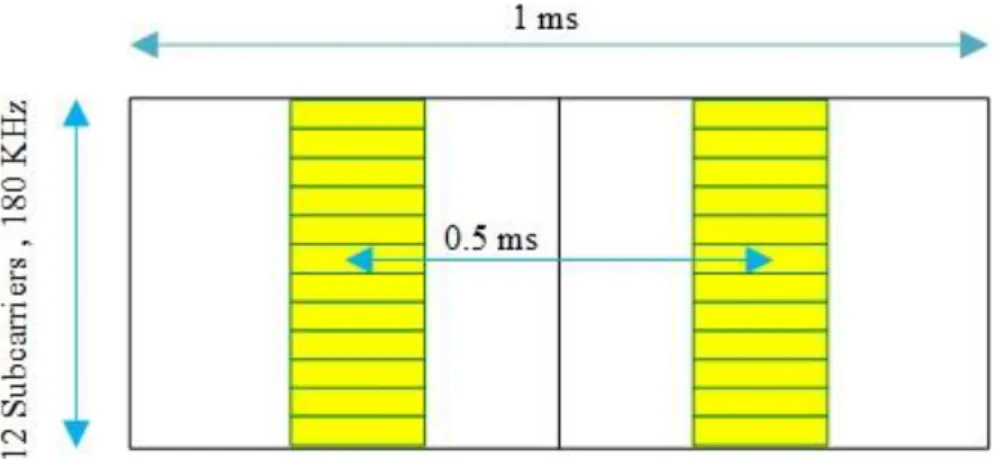
Figure 4-1: 6 subcarriers of 180KHz and 0.5 ms TTI length ... 23
Figure 4-2:12 subcarriers of 180KHz and 0.5ms TTI length ... 23
Figure 4-3: 12 subcarriers of 180KHz and 0.22ms TTI length ... 23
Figure 4-4: 12 subcarriers of 180KHz and 0.25ms TTI length ... 23
Figure 4-5: 12 subcarriers of 180 KHz, doubling the overhead 2/7 ... 25
Figure 4-6: 12 subcarriers of 180 KHz, with modified pilot pattern ... 25
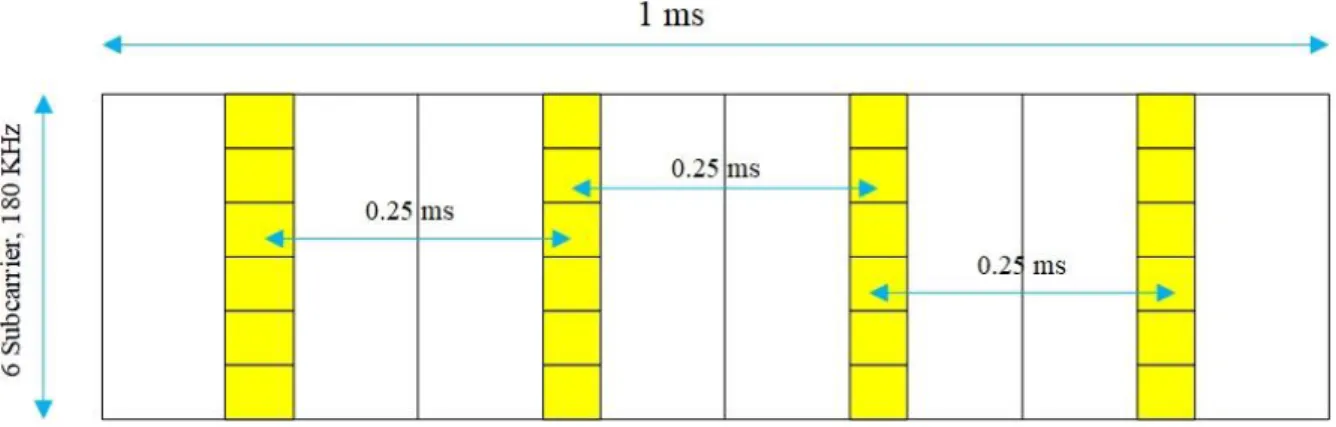
Figure 4-7: 6 subcarriers of 180 KHz in four slots of 1ms frame length ... 25
Figure 4-8: 15 K Hz, Resource block configuration (LTE UL, PUSH) ... 26
Figure 5-1: Resource block and Tile structure ... 29
Figure 5-2: M2M Radio Resources Allocation Algorithm ... 33
Figure 5-3: Scheduling result of 16KHz subcarrier spacing and Multiple subcarrier spacings ... 39
Figure 5-4: Scheduling result of 32KHz subcarrier spacing and Multiple subcarrier spacings ... 40
Figure 5-5: scheduling result of 64KHz subcarrier spacing and Multiple subcarrier spacings ... 41
Figure 5-6: Scheduling result of 128KHz subcarrier spacing and Multiple subcarrier spacings ... 41
1
CHAPTER 1
INTRODUCTION
1.1 Overview
In the past few years development in fifth generation (5G) vision led to the consensus that the latest generation of the cellular communication will be driven by newly emerging use cases. Previously generations of cellular systems have focused only on increasing bandwidth application for human users. Cellular system is expected to play a fundamental role in the efficient deployment of Machine to Machine communication (M2M), providing them with crucial benefits, such as ubiquitous coverage and global internetworking. Features of M2M, however, hinder the deployment through the current cellular system which is based on OFDM particularly for Human to Human communication (H2H). Several works can be found in literature, analyzing the constraints and challenges of Machine Type Communication (MTC), indicating the large number of interconnected devices and the vast diversity of M2M applications and services as the most rigorous ones.
Current M2M applications are based Long Term Evolution (LTE) and LTE Advance, which is designed for H2H communication, if the number of M2M devices is small and overloading in H2H is minimum LTE is an adequate solution for M2M applications, but as the number of interconnected devices increases it proves to be an inappropriate solution, because of its limit capacity and priority to the H2H communication
H2H communication with a new emerging technology i.e. (IoT and smart-grid), that will change our life style is in developing stage. The communication between such machine-type devices is called as Machine to machine communication. The demand of communication between humans increased the growth of advance wireless technologies. 3GPP and LTE and LTE-Adv are project going on for the development of wireless technologies.
2
1.2 Literature Review
Radio resources problem consist on data resources allocation for machine to machine communication and scheduling of signaling. Data resources allocation problem consist on allocation of radio resources for machines to send data. Signaling allocation resources problem consist on allocation of radio resources to start a connection between machine and the base station and send scheduling and control signals from base station to machines. More signaling consume more bandwidth which is not suitable for system performance. For signaling resources many solutions have been proposed in LTE for M2M communication i.e. Backoff methods, and Access Class Bearing (ACB) methods. Moreover, piggy backing method in which in random access procedure devices send data is calculated. These methods have a big drawback that they do not provide QoS guarantees since, they employ a random-access procedure and they do not utilize the priority of M2M communications.
A QoS resources allocation scheme is presented in [1]. In [2] and [3] dynamic resources allocation schemes are presented. These dynamic schemes have large overhead [4] . Moreover, they will not violate periodicity of M2M devices various persistent schemes are presented in literature [5] [6], [7].. Persistent schemes fulfil the periodicity requirements of M2M devices. However, M2M application is a diverse communication consisting on massive numbers of M2M devices while VoIP is an application with very limited diversity. These persistent scheduling schemes are suitable for VoIP and it will not suitable for massive M2M communication. So, we need such a persistent scheduling schemes that can fulfil QoS requirements of massive M2M applications.
In same cellular network the persistent scheduling scheme for radio resources allocation for M2M is presented in [8] and [9]. The author proposed a clustering-based technique to manage radio resources for MTC devices for LTE-Advance stations, MTC devices form clusters with respect to their packet arrival rate and maximum allowable jitter. Each cluster can be accessed in a given access grant time interval and every cluster have given a priority. In proposed scheme, the channel quality which can increase the throughput is not considered. Another drawback of this work is that They allocated entire bandwidth in an access grant time interval to a cluster and did not considered its effect on H2H communications.
3
1.3 Thesis Contribution
Radio resources should be allocated in such a way to both H2H and M2M communication that it satisfies the QoS requirements of H2H and M2M communication. The first approach is that if first we allocate resources of H2H communication and use the remaining resources for M2M devices [10]. However, the disadvantage of this scheme is that it creates the starvation of M2M devices because of heavy H2H traffic [11]. If we prioritize M2M devices it will cause unavailability of resource and delays. Another solution is possible that if we allocated a static bandwidth for H2H communication and some fix part foe M2M communication [12]. Separation of H2H and M2M will solve the starvation and delay problem.
Here we presented a new scheme that minimize the bandwidth occupied by M2M resources used by M2M traffic with strict QoS required for M2M devices. We decrease the number of bands (Frequency bands). The number of bands decreased considering that M2M and H2H devices are allocated separately with different bandwidth allocated for M2M and H2H. The characteristic of M2M communication allows to decrease the signaling cost. The contributions of the thesis are as follow:
We formulated an optimization for radio resources allocation and we decreased the number of bands allocated to M2M devices. we considered strict QoS requirement for M2M devices. We propose a heuristic algorithm and obtained the optimal solution. The algorithm work on priority basis, priority is given to each cluster and machines are allocated with fulfilling the maximum allowable jitter and periodicity requirement of M2M devices.
We proposed the introduction of new device into a new cluster.
1.4 Thesis Outline
We studied the M2M and MTC machine type communication and presented first time in literature a heuristic solution for the allocation of M2M devices.
In fist chapter the basic introduction regarding M2M communication and previous work done and literature review is explained.
4
In preliminaries section prerequisite of M2M communication is explained in detail. Types of M2M communication mMTC and uMTC massive and ultrareliable machine type communication is explained. MTC devices have special requirements, that are explained, Moreover, in chapter-2 we explained that how M2M devices communicating with a server or more than one servers in a network. At the end of chapter two previously allocation schemes like clustering and grouping based radio resources managements are explained.
In chapter-3 the basic parameter for M2M communication Wave Form Candidate is presented. More focused is orthogonal wave form candidate which are more emerging nowadays. OFDM, FBMC and UFMC with their basic parameters is presented. Advantages/disadvantages of wave form candidates are presented over each other.
Chapter-4 consist on frame structure. Two parameters of frame structure are under study in this chapter. TTI size and subcarrier spacing are explained in detail.
Chpater-5 consist on description of optimization problem, System model. An optimal heuristic Algorithm for allocation of M2M devices is also presented and explained with suitable examples. In the end the simulations and results are explained with conclusion.
5
CHAPTER 02
PRELIMINARIES
In this chapter we provide preliminaries required for an understanding of the rest of thesis. mMTC and uMTC type of machine type communication is explained. Requirement of MTC devices and M2M communication supported by 3GPP is explained.
2.1 TYPEES OF MTC
M2M is somewhat elusive as it must include many emerging concepts, such as Internet of Everything (IoE), Internet of Things (IoT), Industry 4.0 smart X, and many more. M2M communication if divided into two categories i.e. massive Machine Type Communication (mMTC) and Ultra-Reliable Machine Type Communication (uMTC).
2.1.1 mMTC
m MTC is the massive connectivity of M2M devices, Millions of devise connecting to each other. A typical example of mMTC is collection of measurement from some massive number sensors, such as smart metering.
6
2.1.2 uMTC
uMTC is MTC devices requiring rather stringent requirements on availability, latency and reliability. For the concept of uMTC, vehicle to X (V2X) communication and industrial control application are the example of uMTC.
2.2 REQUIREMENT OF mMTC DEVICES
MTC devices have following requirements. I. Small packet size.
II. Large number of connected users. III. Uplink transmissions.
IV. Low data rate users. V. Sporadic traffic. VI. Low-complexity
VII. Low energy MTC devices.
2.3 M2M COMMUNICATION SUPPORTED BY 3GPP
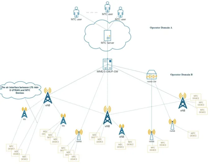
As defined by 3GPP two communications scenarios of M2M communications are supported. i) M2M devices communicating with one or more MTC servers.
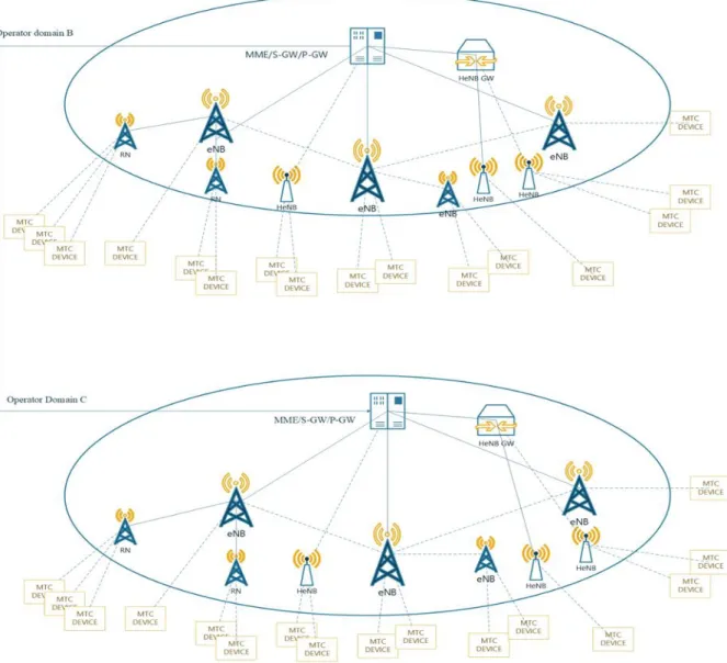
ii) M2M devices communicating with other M2M devices without intermediate M2M servers.
2.3.1 M2M devices communicating with one or more M2M servers
In this scenarios M2M users can operate an enormous number of M2M devices through M2M servers. The operator provides an M2M server, which provides an application program user interface (APUI) for M2M users to access the M2M servers.
3GPP offers the cases for MTC users operated from outside of domain can access the MTC servers.
7
Figure 2-1: MTC devices communication with one or more intermediate server
2.3.2 M2M devices communicating with other M2M devices without
intermediate M2M servers
M2M devices can communicate with each other without requiring M2M servers. M2M devices can communicate in same operated domain or different operated domain. In both cases M2M devices should attached to LTE-Adv base station, and data is forwarded by the LTE-A station. Public land mobile network (PLMN) is used to create communication between M2M devices. PLMN should allow communication between M2M devices and M2M servers. The PLMN is responsible for communication and authentication of M2M devices and M2M servers.
8
Figure 2-2: M2M devices communicating with other M2M devices without intermediate M2M servers
2.4 RADIO RESOURCES ALLOCATION WITH QoS GUARANTEES
1.2.1 Grouping based radio resources management
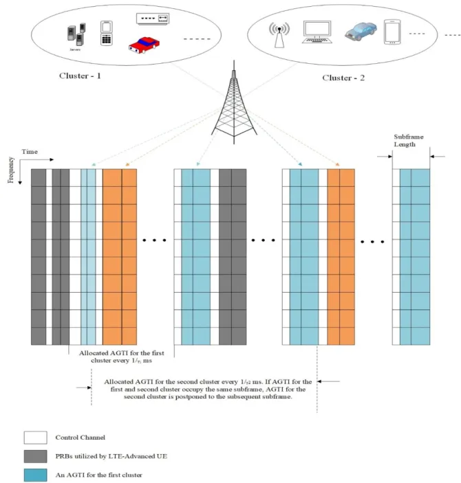
Massive M2M devices with data transmission are allocated using grouping-based resources allocation. M2M devices are grouped into M groups i= 1, …….m based on the packet arrival rate (γi) and maximum allowable jitter (δi). These (γi, δi) are considered as QoS parameters, where γi is ith groups packet arrival rate and δi is ith maximum allowable jitter. M2M devices in the same group occupies same QoS requirements. Apriority is assigned in the groups with the group having higher priority which have higher packet arrival rate γi. Grouping decrease the work load for LTE-A station that can communicate with a group instead of communicating with each machine, which decrease the complexity of access for LTE-A station.M2M devices can communicate in given access grant time interval (AGTI). Therefore, LTE-adv station created L PRBs depending upon 1/ (packet arrival rate) for AGTIs. If two groups arrive for the
9
one AGTI, the group having low priority will served first. The AGTI are shown in Fig 2.3. jitter of packets in the ith group is bounded above by:
δ∗i = τ + ∑ [γk
γi] 𝑓𝑜𝑟 𝑖 = 2, … … . . 𝑀 𝑖−1
𝑘=1 [ [8]]
And for i = 1 for δ*
i = τ. If δ*i ≤ δi for all groups, packets in all groups can meet the jitter requirement.
10
2.4.1 Clustering based radio resources management
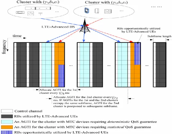
In [1] an efficient algorithm of radio resources allocation for M2M communication is presented. Machines are grouped into M clusters i.e. {i= 1……...M}. Machines are grouped into clusters depending on their QoS requirements. The QoS of each cluster is characterized in three paraments, i.e. maximum allowable Jitter (δi), packet arrival rate (γi) and acceptable probability that jitter violates δi (εi). It was assumed that εi = 0 for a M2M device with an application requiring deterministic QoS and γi for i=1 …. M is known by the Base station. The base station supports a unique packet size for all M2M machines due to small data feature. For each cluster in a given AGTI fix number of L PRB are reserved.
The managements scheme of allocation (Fig. 2.4) is elaborated as follows.
11
Summary
In this chapter we explained the concept of machine to machine communication, type of machine to machine communication depending on the type of connectivity and data type. Two types of machine type communication are explained “Massive machine type communication “in which millions of machines want connectivity with a very small data transfer. Second type of machine type communication is “uMTC”. In this type of machine type communication machine require rather stringent requirements on availability, latency and reliability. Later the requirement of mMTC is explained. mMTC devices have special characteristic and they have special requirement i.e. ten of billions of connectivity with very small data transfer. M2M communication supported by 3GPP is explained. Many works have been done for LTE and LTE-Adv, we explained two types of M2M communication supported by 3GPP i.e. shown in Figure-2.1, Figure-2.2. In the end we explained two type of radio resources allocation i.e. grouping based radio resources allocation and Clustering based radio resources allocation as shown in Figure-2.3 and Figure-2.4
12
CHAPTER 03
WAVE FORM CANDIDATE
Many orthogonal and non−orthogonal wave forms candidate have been proposed for future 5G. FBMC, GFDM and UFMC, OFDM got more attention. Here we will give a brief overview of all orthogonal wave form candidate and some non-orthogonal methods that have been proposed for future 5G. We will give the benefits of these waveforms over each other. The focus here is the radio resources allocations.
3.1 OFDM
The current wireless communication system LTE-Adv consists on OFDM transmitter.
A multi-carrier transmission scheme subdivides the available channel band width into several parallel sub-channels that are called subcarriers. Thus, multiplexing between users can happen in both frequency and time domain. For OFDM several subcarriers are spaced at:
Δf = 1/ Tsymbol
Causing minimum cross-talked, also referred to orthogonality.
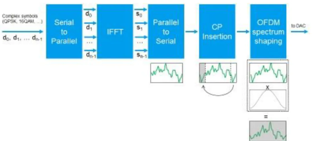
Fig. shows the basic block diagram for an OFDM transmitter. The digital data is mapped to complex symbols such as QPSK, 16QAM, 64QAM or 256QAM etc. depending on the digital standard. A serial parallel conversion turns the data stream into N streams, which correspond to the different carrier frequencies f0, f1, f2, etc. The central carrier (DC) is set to zero. At both edges additional, but unused subcarriers are added to achieve a total of 2N subcarriers, which can be converted from frequency into time domain by an Inverse Fast Fourier Transform (IFFT). To increase robustness against Inter-Symbol Interference (ISI) caused by multipath propagation on the radio channel the total symbol duration is further increased by adding a Cyclic Prefix (CP). A CP is a copy of the tail of a symbol placed at its beginning.
13
Figure 3-1: OFDM Transmitter
Basic parameterization for OFDM in LTE/LTE-Advanced
The main design criteria is maximum expected delay spread Td. The maximum Doppler frequency is defined as fd max = 1/ Td. Cyclic prefix and subcarrier spacing depends on delay spread and Doppler frequency. The propagation characteristic and mobility aspect that are represented by delay spread and Doppler frequency have an impact on choosing cyclic prefix length and subcarrier spacing. The design criteria are as follow:
Tcp ≥ 𝑇d (ISI) fdmax / Δf << 1 (ICI) Tcp Δf ≤< 1
Sub Carrier spacing and OFDM symbol duration
All LTE and LTE-Adv worldwide are using subcarrier spacing Δf 15KHz. As symbol duration (Tsymbol) is inversely proportional to subcarrier spacing so Tsymbol = 1/ Δf. The symbol duration of an OFDM symbol is 66.6µs.
Sampling frequency
With the size of subcarrier spacing of 15KHz and a 20MHz bandwidth tp a size of 2048 the sampling frequency will become as:
14 fsampling = Size of FFT * size of subcarriers spacing 30MHz.
Sub-Frame Duration (TTI) and Number of OFDM Symbols
The duration of a radio frame in LTE is defined with 10 ms. The frame consists of 10 sub-frames of length 1 ms. One sub-frame corresponds to defined transmission time interval (TTI). One sub-frame consists on number of samples 30,720 samples. One sub-frame is further divided into two-time slots of 0.5ms so the number of samples are 15,360 samples. One OFDM symbol is represented by 2048 samples for 20 MHz of bandwidth. Thus 7 OFDM symbol can be placed into one-time slot leaving 1024 samples.
Cyclic Prefix (Tcp)
1024 samples are used for cyclic prefix of 7 OFDM symbols. OFDM symbol in a time slot uses 160 samples and as a cyclic prefix where each of the remaining 6 OFDM symbol uses 144 samples for its cyclic prefix. So, the cyclic prefix will become Tcp = 5.2µs and 4.2µs respectively it is called Normal cyclic prefix. While for subcarrier spacing 15 KHz and 7.5 KHz the extended cyclic prefix is defined. Reducing the number of available OFDM symbols to 6. The cyclic prefix is 512 samples = 16.7 µs for 15 KHz subcarrier spacing and 1024 samples 33.3 µs for 7.5 KHz subcarrier spacing and 3 OFDM symbol.
Doppler frequency and delay spread
During the initial standardization process of LTE, a carrier frequency (fc) = 2GHz was used for all simulation results. Maximum Doppler frequency is impacted by carrier frequency and velocity of the system shall support. The maximum delay spread is 991 ns but in cities is upto 3.7 µs. [ [13] ]
LTE is means to support a high-speed train HST and thus speeds up to v = 300 km/h with the Doppler frequency defined as fdmax = fc (v/c), where c corresponds to speed of light fdmax = 555Hz.
15
3.1.1 Limitation of OFDM
OFDM has certain limitation that makes it not more suitable wave form for all the targeted applications. The new service can be better introduced by the definition of alternative wave form that complement the weaker aspect of OFDM.
Here we discuss some limitation of OFDM.
Cyclic prefix Overhead
The addition of cyclic prefix adds redundancy since the same content transmitted twice as the cyclic prefix is the copy of the tail of a symbol placed at its beginning. The duration of cyclic prefix can be expressed as:
βoverhead = Tcp / (Tcp + Tsymbol) --- [14]
For normal cyclic prefix the cyclic prefix overhead βoverhead is about 6.6% to 7.2%, while for extended cyclic prefix the βoverhead is 20% and 33.3 % which is very high.
Sensitivity to Frequency and Timing offset
The orthogonality in OFDM assumes that transmitter and receiver using exact the same reference frequency. In terms of frequency offset the orthogonality is lost, causing subcarrier leakage known as Inter-carrier interference (ICI). Frequency errors typically arise by drifts of the local oscillator which are typically a function of voltage variations and temperature changes. Phase Noise adds to this error and mm-Wave frequencies turns into OFDMs Achilles heel. The true impact of phase noise, however, depends on the design approach to generate the signal.
High Peak to average power ratio
Another disadvantage of OFEM is high peak to average power ratio (PAPR) causing crest factor (CF). The high PAPR compared to single-carrier transmission technique occurs due to summation of many individual subcarriers. At each instant the typically subcarriers have different phase compared to each other, however sometimes they have same value simultaneously which lead to output power to ‘peak’. Due to high number of subcarriers in an
16
OFDM system such as LTE supporting up to 20 MHz bandwidth per carrier, the peak value can be very high compared to average value.
Single carrier frequency division multiple access (SC-FDMA) access technology is used to lower the PAPR of OFDM in LTE systems.
Spectral Regrowth
Connective OFDM symbols are independent of each other, there is a discontinuity in time domain. This discontinuity translates to spectral spikes in the frequency domain. This can be improved time domain time domain windowing that smooth the transmission from one symbol. This cost the overlap of signals and error vector magnitude (EVM) increases. For a sampling rate 30.72 MHz a transition time of 1 µs translates to 30 samples overlap. To solve this for a 20MHz LTE signal 1MHz guard band is applied at left and right, that reduces the signal band width to actual transmitted band width from 20MHz to 18 MHz.
3.2 FBMC Filter Bank Multi Carrier
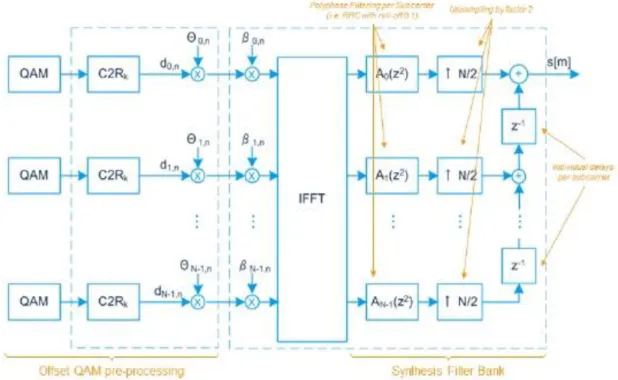
Filter bank Multi Carrier (FBMC) is proposed wave form candidate for 5G. FBMC applies filtering on a subcarrier level while using filter bank on transmitter and receiver side. There are different implementations of FBMC, Staggered modulation multi-tone (SMT) and Filter modulated-tone (FMT), Cosine multi-tone (CMT). [ [15]][ [16]][ [17]]
SMT shows higher spectral efficiency and it is more promoted than FMT, So, he the focus is on SMT.
In Fig the SMT FBMC transmitter is shown.
A linear phase finite identical response (FIR) prototype filter based on Root raised cosine (RRC) with a roll-off factor of 0.1 is used to create N poly-phase filter Ak of length K. K tells us overlapping factor that characterizes the prototype filter and defines the number of super imposing symbols in time.
For FBMC the overlapping is 4.0. The filter bank is created by applying k/N shift of the proposed prototype filter. This impact orthogonality as energy spreads now between adjacent subcarriers and thus created ICI between adjoining subcarriers. However, all even subcarriers are orthogonal, and all odd subcarriers are orthogonal as they do not overlap each other. If we
17
use of OQAM can remove interference easily as if we ignore the symbols that are carrying data.
The filtering functionality for FBMC is per subcarrier level, which in response gives us long filter tail, which require filter to be very tight filtering. It is necessary to use the filter length at least three or four times the length of symbol. So, for bursty data communication we can manage for ramp up and ramp down.
Figure 3-2: FBMC Transmitter
3.2.1 Disadvantages of FBMC
Here we will explain issues with FBMC and how to decrease these issues.
Subcarrier Spilling Interference
The subcarrier interference to its neighbors in FBMC arises due to channel estimation. We have a real pilot p, the symbol S is transmitted over subcarrier L is as follow:
18
I is the interference generated by the data present in the surrounding of the pilot subcarrier. When this is passed through a channel H, the received symbol will be:
R=HP= H(p + SI) The estimated channel is:
Ĥ=R/p = H (1+ S I/p) = H + SH 1/p Typically, H is complex, so we can estimate to separate it without data.
Loss of Orthogonality with Multiple User Sharing the channel
When multiple user share channel, at the end of the frequency edges interference occurs. This effect the orthogonality which can be managed by using OQAM symbol. The complex multi-user receiver or capacity reducing guard must applied.
MIMO schemes Like Alamouti (Space-Time Coding) does not work Schemes depends on complex symbols which affected by the interference.
Insufficient for short burst due to longer filter tails
SMT filtering cause long filtering tail with long impulse response for short burst transmission. Which is very painful [18].
3.2.2 Advantages of FBMC
FBMC have many advantages that enables several scenarios targeted to 5G M2M applications. [19]
1. A synchronous transmission. 2. Suitable for fragmented spectrum. 3. Robust
4. Efficient adaptation of subcarrier spacings
3.3 UFMC Universal Filter Multi-Carrier / Filtered OFDM
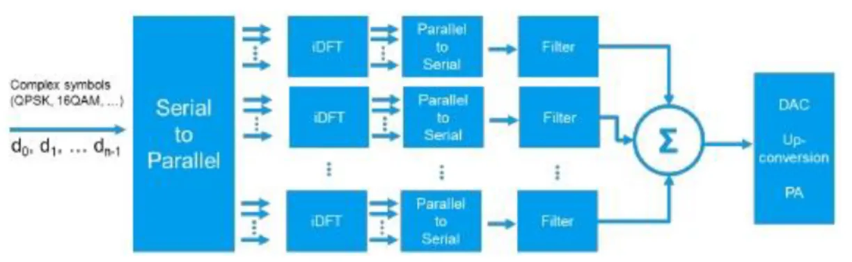
The UFMC is the generalization of filtered OFDM and FMT. [ [20]] [21] [22] [23] UFMC group subcarriers to sub-bands that are then filtered. The number of carrier per bands and the filter paraments are common between UFMC and FBMC. Non-contagious bands can be allocated in UFMC this increase the flexibility in terms of utilization of spectrum. Ultimately,
19
we may say that UFMC is a compromise between FBMC and OFDM. In Figure 3.3 the UFMC transmitter is given.
Typically, the size of FFT window increase in UFMC, which result higher complexity in the implementation. The insertion of guard interval as cyclic prefix is optimal in UFMC. The important feature of UFMC as unified structure is the usage of multiple single layer. User can be differentiated based on the interleaves as it was done in Interleave-division- multiple-access (IDMA) [24]
Figure 3-3: UFMC Transmitter
3.3.1 Advantages of UFMC
UFMC is the strongest candidate for future 5G. It has many advantages over other explained wave form candidates. Here some advantages of UFMC are explained.
High Spectral efficiency
UFMC is more efficient than OFDM. It has high spectral efficiency. [22]
Well Suited for Short Burst Transmission UFMC is well suited for short Burst transmissions.
Orthogonal With respect to complex plain
UFMC is orthogonal with respect to complex plane. [22]
Flexibility in subcarrier spacing
20
3.3.2 Disadvantages of UFMC
1. For high data rates orthogonality is lost. Not suitable for high data rates. 2. The large FFT size increases complexity at receiver end.
3. Interference will be observed for partly overlapping sub-bands.
4. UFMC shows the same behavior with a rectangular pulse shape for Carrier-Frequency-offset (CFO).
Summary
In this chapter the wave form candidate is explained, as wave form candidate offer flexibility towards radio resources allocation, so consideration of wave form is as important as resources allocation and flexible frame structure. Many wave form candidates have been proposed for future 5G but we considered only OFDM, FBMC, GFDM and UFMC. As these wave form candidates are potential candidates for future 5G. Initially we explained OFDM with OFDM transmitter shown in Figure-3.1. The working of OFDM in current LTE and LTE-Adv is explained with advantages and disadvantages of OFDM. Later FBMC is explained, as shown in Figure-3.2 FBMC transmitter is given, the importance of FBMC is Filter bank. Three types of filter bank can be considered SMT, FMT and CMT. But here we considered SMT. Later advantages and disadvantages of FBMC are explained. The major disadvantage of FBMC is that it is not orthogonal. FBMC is still in the process of improving. In the end Filtered-OFDM/ UFMC is explained. UFMC have many advantages over OFDM and FBMC. The parallel filtering in UFMC makes it stronger and it is compatible with old OFDM system. So, it is potentially a strong candidate for 5G. Still it has some disadvantages explained above. The transmitter of UFMC is shown in Figure-3.3.
21
CHPATER 04
FLEXIBLE FRAME ARCHITECTURE
5G wireless communication require such a flexible frame design that allows to allocate Massive MTC devices. The ability to adapt efficiently and optimize the radio resources for each user in coherence with its service requirement is needed. This require highly flexible frame structure. There is consensus that 5G should push the performance limits significantly further towards having virtually zero latency and multi-gigabit-rate end user experience, and efficient machine type communication, depending on the application requirement [25] [26].
4.1 Available spectrum
Until now the spectrum that is allocate for wireless communication is below 6 GHz. World Radio conference is expected to consider band allocations greater than 6 GHz for future 5G deployment.
Spectrum below 6GHz is rather fragmented and composed of mixture of bands for operating with frequency division duplex (FDD) and Time division Duplex (TDD). Depending on the region, the 2GHz of spectrum is still available for future mobile communication with equal availability of bands for FDD and TDD deployments. Bands for FDD are available under 3 GHz, some FDD bands are available at higher frequencies.
22
4.2 Time-frequency Multiplexing of users for 5G
4.2.1 TTI size
1 ms is required for Mission Critical Communication (MCC), so TTI is no more than 0.2 – 0.25 ms is needed. The TTI size can be dynamically adjusted, so come users can be scheduled with short TTI size of Δt to fulfil the Round-Trip-Time (RTT) required for MCC. All users are not optimal with this kind of scheduling.
. Long TTI benefits for Mobile broad band (MBB), as required data rate is high, and latency required is less. The flexibility to schedule users with different TTI sizes offers further advantages. The user with moderate path loss towards their serving base station are schedule-able on larger bandwidth with short TTI sizes, coverage challenged UEs need to be scheduled with longer TTI on a narrow bandwidth to have a sufficiently high received energy to the base station
Here we define different choices for designing recourse block structure the selection of TTI and symbol duration.
The 1st choice is 12 subcarriers of 180KHz and 0.5ms TTI length or 6 subcarriers of 180KHz and 0.5 ms TTI length as shown in Figure 4.1 and 4.2.
The 2nd choice is 12 subcarriers of 180KHz and 0.22ms TTI length or 12 subcarriers of 180KHz and 0.25 ms TTI length. i.e. reduced number of symbols per block as shown in Figure 4.3 and 4.4.
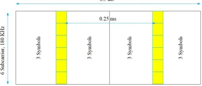
The 3rd choice is 3 subcarriers of 180KHz 0.25ms TTI length, shorten the single symbol connected with increasing the subcarrier spacing.
The 4th choice is 6 subcarriers of 180KHz, 0.25ms TTI length, a combination of reduce number of symbols per block and shorten symbols connected with increasing subcarrier spacing.
23
Figure 4-1: 6 subcarriers of 180KHz and 0.5 ms TTI length
Figure 4-2:12 subcarriers of 180KHz and 0.5ms TTI length
Figure 4-3: 12 subcarriers of 180KHz and 0.22ms TTI length
24
4.3 Subcarrier spacing
In addition to the time-domain scheduling flexibility, the frame structure also allows dynamic frequency domain scheduling, The MTC devices served within a narrow bandwidth can be scheduled with a longer TTI size to gain from time diversity.
By using flexible frame architecture, a flexible 5G frame structure design for frequency division duplex (FDD) is presented. Using fixed subcarrier spacing 16 KHz and 32 KHz and fixed TTI size 0.2ms, allocated 16,800 resource elements per second for 20MHz carrier. Subcarrier spacing and TTI size is the building parameters of frame design.
∆fmax ≤ Bc Where Bc is the coherence bandwidth.
Bc =1/ 50Td fdmax ∆f << 1
Different numerology designs are presented for flexible choice of subcarrier spacing.
The 1st choice is 12 subcarriers of 180 KHz, subcarrier spacing is 15 K Hz, in two slots of 1 ms frame length with LTE like setting as shown in Figure 4.8.
The 2nd choice is, double subcarrier spacing i.e. 30 KHz subcarrier spacing and 6 subcarriers of 180 KHz in four slots of 1ms frame length as shown in Figure 4.7.
The 3rd choice is 12 subcarriers of 180 KHz, subcarrier spacing is 15 KHz but doubling the overhead 2/7 as shown in Figure 4.5.
The 4th choice is 12 subcarriers of 180 KHz, with modified pilot pattern but with the same overhead as mentioned in choice 3 shown in Figure 4.6.
25
Figure 4-5: 12 subcarriers of 180 KHz, doubling the overhead 2/7
Figure 4-6: 12 subcarriers of 180 KHz, with modified pilot pattern
26
Figure 4-8: 15 K Hz, Resource block configuration (LTE UL, PUSH)
Summary
In this chapter we explained some previous work of flexibility, and how we may consider flexibility in the frame design. We considered two parameters subcarrier spacing and TTI size. How we may consider the degree of freedom for subcarrier spacing, we may consider dynamically subcarrier spacing and TTI size. In Figure-4.1 to Figure-4.4 different size of TTI and symbol duration is selected to give the concept of flexibility and advantages. In Figure-4.5 to Figure-4.8 of considering different subcarrier spacing is shown. Different choices form choice 1 to 4 is given for choosing TTI size and symbol duration with subcarrier spacing. For choosing subcarrier spacing we are bounded by equation-1 to equation-3. Different choices from choice 1 to 4 is given for choosing subcarrier spacing.
28
CHAPTER 05
M2M RESOURCES ALLOCATION ALGORITHM
In this chapter we will analyze newly proposed M2M Resources Allocation Algorithm for the case when we have more than one subcarrier spacings. The Model and basic approach is same.
5.1 System Model
1) We consider a cellular system with a base station which serves massive M2M devices with diverse traffic characteristics in addition to H2H devices.
2) We propose quality of service constrained scheduling for massive M2M communication in future cellular network. Each machine Mi having period requirement p and jitter di with the packet arrival rate tPAR. The QoS requirements of time-triggered periodic data generating M2M devices are measured by jitter di. Jitter di is defined as “the time difference between two successive packet departures and packet arrivals”. Periodic M2M devices have a maximum allowed jitter know as jitter tolerance δi. Every MTC group have different priority of access depending upon the periodicity.
3) For event-triggered H2H devices generating data randomly, QoS is measured by delay/latency td.
4) M2M devices are allocated to Resource Block RB. Resource blocks are time frequency resource elements. The structure of a RB is illustrated in Figure.5.1. As shown, each
29
RB has a certain number of sub-carriers iSc i ∈ {1, ...,β}, and time symbols St , t ∈ {1, ...,α}. These sub-carriers have the same width, for one RB, which is called sub-carrier spacing ∆f. This make the symbol duration Ts identical in one RB. The number of symbols α along with symbol duration Ts determines the length of a RB. In LTE, a resource block is a time-frequency unit with β=12 sub-carriers each with ∆f=15 KHz which make 180 KHz width in frequency, and α=7 symbols in time which make 0.5 ms length in time.
5) The size of a RB in frequency and time domains may be flexibly changed to meet QoS requirements of a group of an M2M devices which have some similar characteristics. The change of a RB size means changing the sub-carrier spacing ∆f and accordingly the useful symbol duration Ts of each resource element of a RB while keeping the number of sub-carriers and symbols of each RB constant (α symbol, β sub-carrier). M2M devices with critical delay or jitter requirement will be allocated RBs having shorter symbol duration Ts but wider in frequency ∆f, whereas delay-tolerance M2M devices which may send periodic data over long periods, e.g. one packet per minute/hour, will be allocated RBs having a relaxed symbol duration Ts but narrower in frequency ∆f and this will increase the utilization bandwidth.
30
5.2 Details of optimization problem
We presented an optimization problem in this section. The aim is to minimize the number of bands occupied by M2M devices. The chosen constraints for problem is period and jitter requirement of M2M devices. We give the details of the problem and showed that it is a 3-partition problem, which is NP-Hard problem. We presented a heuristic first search algorithm to get optimal results.
5.2.1 Constraints of Problem
As given earlier that the jitter tolerance and period of the time-triggered M2M devices are the QoS constraints. We must ensure that QoS should not be violated which means jitter bound i.e. jitter tolerance [8] never be violated.
Jitter bound is given in equation-1 [9] for variable TTIs. N time-triggered devices are arranged according to priority i.e. if device Y is prior to device Z then Y<Z. The jitter bound of the device is δ*i with TTI is τi while period of device is pi, di is the jitter tolerance of device.
δ* i = τi + ∑ 𝑃𝑖 𝑝𝑙 𝑖−1 𝑙=𝑖 * τl ≤ di (1) for i = 1…., N
5.3 Optimization problem
The optimization problem is given as bellow, and the problem is a binary linear programming (BLP) problem. Minimize ∑ 𝑦𝑘 𝐾 𝑘=1 𝑓𝑘 (2) Subjected to
31 ∑𝐾𝑘=1𝑥𝑖𝑘 = 1 for i= 1,...N (3) ∑𝑁𝑖=1𝑥𝑖𝑘 ≤ Nyk for i= 1,...N (4) τi + ∑ 𝑃𝑖 𝑝𝑙 𝑖−1 𝑙=𝑖 * τ l xlk 𝑓𝑘 ≤ di + (1- xik) Ti (5) for i = 1, . . .. N for k = 1, ….. K Variables yk ϵ{0,1}, (6) for i = 1, . . .. N for k = 1, ….. K where Ti = τi + ∑ 𝑃𝑖 𝑝𝑙 𝑖−1 𝑙=𝑖
*
τ
l - di ; Ti shows that (5) is always satisfied when xik = 0. yk is a binary variable taking that value 1 if any device is allocated to UFB k, and 0 otherwise. 𝑓𝑘 is the number of bands occupied by M2M machines. The aim is to minimize the number of band occupied by M2M devices. It is given in equation (3) that one device should be allocated to one Resource block, while equation (4) shows that if band is occupied or not occupied. . Equation (5) represent the jitter bound.5.4 NP-Hardness of Optimization Problem
Theorem 1: The optimization problem presented previously is NP-Hard.
Proof: Let consider case when pi and di are equal while xi = τi where B/4 < xi < B/2 for i ϵ [1,3k] and B ϵ Z+. We will prove that our problem is a 3-partition problem.
5.5 Minimum Bands First-Fit Allocation Algorithm
The base station has already a high load of H2H communication and massive M2M communication. We presented a simple first search algorithm for massive M2M communication to put strain for LTE/5G. The resources allocation need to be a simple and computationally simple algorithm.
We presented a simple first search heuristic algorithm. Machines are grouped for more simplicity and efficiency. First, we find that which bands are suitable for which groups of machines and then M2M devices are allocated to such bands.
32
5.6 Description of Algorithm
In this section we presented a heuristic algorithm. This is the most fit allocation algorithm. Ni is the number of unallocated machines present in each group. Machines are grouped into M clusters. di is the cross jitter which is observed due to machines present due to higher priorities. kRB
SC is (M x k x SC) dimensional vector storing the number of devices from each M group in k bands. SC is the different subcarrier spacings i.e. that starts from 2k. Here the maximum choosing value for k is 7 and minimum value is 4. So, four different subcarriers spacing have been chosen. But we can increase or decrease the number of subcarrier spacings. kRBSC is initialized initially. Algorithm initially check the suitable bands for each group. Devices from first higher priority group are allocated. Cross jitter is observed for second group due to previously allocated devices in that band. Then machines are allocated in the corresponding Bands.
33
34
5.7 Algorithm Example
The algorithm example is presented in this section. The characteristic of M2M devices for example are shown in Table-1. Groups have assigned priority that is a group having low priority will be served first, which means cluster 3 has lowest priority while cluster 1 has highest priority. So, we begin allocating devices form cluster 1, initially there is no device allocated in first band so and cluster 1 has highest priority so cross jitter will be 0 in this case. The remaining jitter can be calculated as by d1 – crossjitter = 4 - 0 = 4. We can allocate remjitter/T1 = 4/1 = 4 devices from group A allocated in first band’s RB. We will update 1RB1 = 4, now we try to allocate devices from group 2 to first band with group 1. The jitter imposed on group 2 from group 1 is, 1RB1 *(p2/p1)*T1 = 6 , As 6 > d2 =5 , which means imposed jitter of group 2 is higher than jitter tolerance of the group, so we cannot allocate any device from group 2 with Group 1 in band. We will do the same with group 3, in this case Jitter imposed on 1 by 3 is 8 > d3. So, we cannot allocate devices from group 3 with group 1 in first band. Now we proceed with the second group, the second highest priority group, the cross jitter is 4 < d2, the remaining jitter is 1. So, we can allocate remjitter/T2 =1 device from group 2. For the group 3, the devices impose jitter is 5 >d3 . So, devices from group 3 cannot be allocated with group 1 and 2 in second band of first subcarrier spacing. Now the devices in the first group are zero so we will look for the chosen subcarrier spacing for group 2 i.e. SC+1, With this same procedure we will allocate devices of all groups in different subcarrier spacings.
Table 1 : Parameters of Example
Groups Cluster 1 Cluster 2 Cluster 3
N 4 3 4
P 4 5 6
D 4 5 4
35
5.7.1 Algorithm Matlab an Example
In this section we will present an example and we will show that the presented algorithm gives us optimal result i.e. the number of machines of all groups will occupy minimum band width. Frame Parameters are defined in the table-2. 2k subcarrier spacing is chosen k starts from 4 to
7. The corresponding TTI size and number of symbols are shown in table-2.
k Δf = Subcarrier spacing Symbol Duration Number of symbols
4 16 KHz 0.0625 ms 16 Symbols
5 32 KHz 0.03125 ms 32 Symbols
6 64 KHz 0.015625 ms 64 Symbols
7 128 KHz 0.0078125 ms 128 Symbols
Table 2: Subcarrier Spacing and corresponding Symbol duration & number of symbols
Subcarrier Spacing and corresponding Symbol duration & number of symbols
From the above-mentioned frame parameters 128KHz to 16KHz subcarrier spacings have been chosen for allocation of devices presented in table-3. We allocated the machines in single subcarrier spacings and multi subcarrier spacings and compared the benefits of multi subcarrier spacings over single subcarrier spacings.
Group 1 Group 2 Group 3 Group 4 Group 5 Group 6 Group 7 Group 8 N 20 12 18 25 34 43 30 32 p 0.12 0.24 0.3 0.36 0.42 0.54 0.66 0.72 d 0.12 0.24 0.3 0.36 0.42 0.54 0.66 0.72
Table 3: M2M Machines Parameters for performance evaluation
Initially we chose 128KHz single subcarrier spacing and allocated all the groups. For chosen subcarrier spacing the TTI size will be:
T=
[0.0078125,0.0078125,0.0078125,0.0078125,0.0078125,0.0078125,0.0078125,0.00 78125];
36
The output matrix showing the allocation of devices in 128KHz subcarrier spacing.
Each column in RB(128KHz) represent of one MTC group. Each row represents 128KHz band. Total band width occupied by the MTC groups sum of the bandwidth of total bands occupied by MTC groups and are equal to 5* 128KHz = 640KHz.
Now, we chose 64KHz single subcarrier spacing and allocated all the groups. For chosen subcarrier spacing the TTI size will be:
T=
[0.015625,0.015625,0.015625,0.015625,0.015625,0.015625,0.015625,0.015625]; The total band width occupied by the MTC groups is sum of the bandwidth of total bands occupied by MTC groups and are equal to 10* 64KHz = 640KHz.
We repeat the same procedure with 32 KHz subcarrier spacing. The TTI size for 32KHz The total band width occupied by the MTC groups is sum of the bandwidth of total bands occupied by MTC groups and are equal to 19* 32KHz = 608KHz.
We repeat the same procedure with 16 KHz subcarrier spacing. The TTI size for 16KHz subcarrier spacing is shown as follow:
T= [0.0625,0.0625,0.0625,0.0625,0.0625,0.0625,0.0625,0.0625];
The total band width occupied by the MTC groups is sum of the bandwidth of total number of bands occupied by MTC groups and are equal to 39* 16KHz = 624KHz.
So, the minimum solution lies in 32KHz subcarrier spacing and that is 608KHz bandwidth.
Now we will allocate MTC groups shown in Table-3 with multiple subcarrier spacings from 128KHz to 16 KHz subcarrier spacings. The algorithm will pick suitable subcarrier spacings for each group. In our case the subcarrier spacings are as follow:
SC = [2 1 2 2 1 2 2 1]
1 stands for first subcarrier spacing and two stands for 2nd subcarrier spacing, So, 16 KHz and 32KHz subcarrier spacings have been chosen as show in SC.
The total band width occupied by the MTC groups is sum of the bandwidth of total number of bands occupied by MTC groups and are equal to {(8* 16) + (15*32)} KHz = 608KHz.
37
This result shows that if we allocate the MTC groups in multiple subcarrier spacings it will always occupy lowest band width as shown in the above example.
5.8 Performance Evaluation
In this section we compare the performance of the proposed heuristic algorithm to previously proposed algorithms and showed that the results are optimal in comparison to all previously allocation schemes in terms of scheduling and band width optimization.
In ( [30] simulation results re shown for LTE. It includes a single cell with uplink transmission. The available band width is 5MHz, which means 25 resource blocks are available per TTI. The number of devices ranges from 10 to1500.
We simulated results for using multiple single subcarrier spacings and i.e. starting for 16KHz to 128KHz. We obtained following results shown in Table-4.
Period and jitter characteristics are shown in Table-5.
Number of Clusters Number of Machines Bandwidth Occupied using 16KHz single Subcarrier-Spacings (KHz) Bandwidth Occupied using 32KHz single Subcarrier-Spacings (KHz) Bandwidth Occupied using 64KHz single Subcarrier-Spacings (KHz) Bandwidth Occupied using 128KHz single Subcarrier-Spacings (KHz) Bandwidth occupied using multiple subcarrier spacings (KHz) 8 232 640 640 640 640 640 8 257 832 832 832 832 880 8 267 880 864 896 896 864 8 277 960 960 960 960 944 8 287 1008 992 1024 1024 992 8 297 1040 1024 1024 1024 1024 8 337 1168 1152 1152 1152 1152 8 352 1200 1184 1216 1216 1200 8 362 1216 1216 1216 1216 1216 8 370 1232 1216 1216 1216 1216 8 380 1248 1248 1280 1280 1232 8 390 1264 1248 1280 1280 1248
38 8 400 1280 1280 1280 1280 1264 8 430 1360 1376 1344 1344 1360 8 440 1456 1440 1472 1536 1440 8 480 1584 1568 1600 1664 1568 8 550 1728 1728 1728 1792 1728
Table 4: Comparison of bandwidths using single subcarrier spacings and multiple subcarrier spacings.
Period and jitter of the clusters is as given. P= [0.12,0.24,0.3,0.36,0.42,0.54,0.66,0.72] P= [0.12,0.24,0.3,0.36,0.42,0.54,0.66,0.72]
39
5.9 Scheduling Performance
Figure-5.3 compare the scheduling of our proposed MFFFA algorithm with single subcarrier spacings. Chosen single subcarrier spacing is 16 KHz and we compare the results with multiple subcarrier spacings. The algorithm selects the optimal subcarriers spacing from the given choices from 16KHz to 128KHz. 8 Clusters have been chosen to check the simulation performances with random distribution of machines in clusters. Number of machines starts from 230 to 550 increasing randomly in clusters. Strict periodicity requirement has been chosen with the assumption that jitter is equal to period. The data is given in table-1 and table-2.
Figure 5-3: Scheduling result of 16KHz subcarrier spacing and Multiple subcarrier spacings
The graph shows that the if we use single subcarrier spacing of 16KHz for the allocation of devices it occupies higher bandwidth in comparison to multiple subcarrier spacings. The worst- case performance is that when the bandwidth occupied by multiple subcarrier spacing is equal to single subcarrier spacings.
Fig-5.4 compare the results of bandwidth occupied by using multiple subcarrier spacings with 32KHz subcarrier spacings. The results are quite interesting if we compare the results with
40
32KHz single subcarrier spacing as 30 KHz is supposed subcarrier spacing for 5G so the results are very close or similar in this section if we compare with multiple subcarrier spacing. But if you observe that while moving from number of machines 350 to 450 the results are comparatively very low in-comparison to 32KHz single subcarrier spacings. Which shows that when the number of machines increases the in clusters and the number of cluster increases the we will obtain optimal result using multiple subcarrier spacing for the scheduling of M2M devices.
Figure 5-4: Scheduling result of 32KHz subcarrier spacing and Multiple subcarrier spacings
Fig-5.5 and 5.6 compare the results of scheduling performance of single subcarrier spacing 64KHz and 128KHz with multiple subcarrier spacings. 64 and 128KHz subcarrier spacings cannot be a solution for the scheduling of M2M devices because the bandwidth difference is very high. As the selected number of devices are very small and M2M require massive connectivity of millions of devices in that case the scheduling performance goes much worse for using single subcarrier spacing using 64 and 128 KHz subcarrier spacings.
41
Figure 5-5: scheduling result of 64KHz subcarrier spacing and Multiple subcarrier spacings
42
5.10 Conclusion
We discussed the problem for M2M radio resources allocation. We formulated an optimization problem and proved that the problem is NP hard and solved it for massive M2M devices using heuristic algorithm. The simulation results show that multiple subcarrier spacing is containing feasible and optimal set of solution than the all other previously presented solution. Some solution of Single subcarrier spacing are close to the solution of multiple subcarrier spacings, but we are not able to use because we cannot find the optimal solution for all set of devices using that single subcarrier spacing. We need such type of allocation that give us optimal results with fulfilling strict QoS requirement for all devices that can be achieve only using multiple subcarrier spacing allocation. In future this work can be extended to use for higher subcarrier spacing greater that 128KHz.
43
References
[1] C. A. -. H. a. M. Dohler, Machine-to-machine (M2M) communications: architecture, performance and applications, Elsevier, Dec 23, 2014.
[2] D. H. T. L. CY Oh, "Joint access control and resource allocation for concurrent and massive access of M2M devices," IEEE Transactions on Wireless Communications, vol. 14, no. 8, pp. 4182 - 4192, Aug. 2015.
[3] K. W. C. D T Wiriaatmadja, "Hybrid Random Access and Data Transmission Protocol for Machine-to-Machine Communications in Cellular Networks," IEEE Transactions on
Wireless Communications , vol. 14, no. 1, pp. 33 - 46, Jan. 2015.
[4] N. Afrin, J. Brown and J. Y. Khan, "Design of a buffer and channel adaptive LTE semi-persistent scheduler for M2M communications," London, UK, 2015.
[5] A. G. Gotsis, A. S. Lioumpas and A. Alexiou, "M2M Scheduling over LTE: Challenges and New Perspectives," IEEE Vehicular Technology Magazine, vol. 7, no. 3, pp. 34 - 39, September 2012.
[6] J.-B. Seo and V. C. M. Leung, "Performance Modeling and Stability of Semi-Persistent Scheduling with Initial Random Access in LTE," IEEE Transactions on Wireless
Communications, vol. 11, no. 12, pp. 4446 - 4456, December 2012 .
[7] H. W. E. M. ,. a. E. T. D Jiang, "Principle and Performance of Semi-Persistent Scheduling for VoIP in LTE System," Shanghai, China, September 2007.
[8] S.-Y. Lien and K.-C. Chen, "Massive Access Management for QoS Guarantees in 3GPP Machine-to-Machine Communications," IEEE Communications Letters, vol. 15, no. 3, pp. 311 - 313, Mar 2011.
[9] S.-Y. Lien, K.-C. Chen and Y. Lin, "Toward ubiquitous massive accesses in 3GPP machine-to-machine communications," IEEE Communications Magazine, vol. 49, no. 4, pp. 66 - 74, April 2011.
[10] S. Zhenqi, Y. Haifeng, C. Xuefen and L. Hongxia, "Research on uplink scheduling algorithm of massive M2M and H2H services in LTE," Beijing, China, 29 April 2013. [11] A. M. Maia, D. Vieira, M. F. d. Castro and Y. Ghamri-Doudane, "A mechanism for
uplink packet scheduler in LTE network in the context of machine-to-machine communication," Austin, TX, USA, Dec. 2014.
44
[12] A. S. L. A. Antonis G. Gotsis, "Analytical modelling and performance evaluation of realistic time-controlled M2M scheduling over LTE cellular networks," Transactions on
Emerging Telecommunications Technologies, vol. 24, no. 4, pp. 378 - 388, June 2013 .
[13] 3. T. 36.101, User Equipment (UE) radio transmission and reception V12.9.0, October 2015 (Release 12).
[14] I. T. M. B. Stefania Sesia, "LTE - From Theory to Practice",, 2009.
[15] B. Farhang-Boroujeny, "OFDM Versus Filter Bank Multicarrier," IEEE Signal
Processing Magazine, vol. 8, no. 3, pp. 92 - 112, 2011.
[16] M. Bellanger, "Physical layer for future broadband radio systems," New Orleans, LA, USA, Jan 2010.
[17] G. Ndo, H. Lin and P. Siohan, "FBMC/OQAM equalization: Exploiting the imaginary interference," Sydney, NSW, Australia, Sept. 2012.
[18] M. a. others, "FBMC physical layer : a primer," PHYDYAS , 06/2010.
[19] F. Schaich, "Filterbank based multi carrier transmission (FBMC) — evolving OFDM: FBMC in the context of WiMAX," Lucca, Italy, April 2010.
[20] G. W. a. others, "5GNOW: non-orthogonal, asynchronous waveforms for future mobile applications," IEEE Communications Magazine, vol. 52, no. 2, pp. 97 - 105, Feburary 2014.
[21] G. W. a. others, "5GNOW: Challenging the LTE Design Paradigms of Orthogonality and Synchronicity," Dresden, Germany, June 2013.
[22] F. Schaich, T. Wild and Y. Chen, "Waveform Contenders for 5G - Suitability for Short Packet and Low Latency Transmissions," Seoul, South Korea, May 2014.
[23] V. Vakilian, T. Wild, F. Schaich, S. t. Brink and J.-F. Frigon, "Universal-filtered multi-carrier technique for wireless systems beyond LTE," Atlanta, GA, USA, Dec. 2013. [24] K. Kusume, G. Bauch and W. Utschick, "IDMA vs. CDMA: Analysis and Comparison
of Two Multiple Access Schemes," IEEE Transactions on Wireless Communications , vol. 11, no. 1, pp. 78 - 87, January 2012.
[25] I. V. ITU-R SGs, " Framework and Overall Objectives of the Future Development of IMT for 2020 and Beyond," Feb. 2015.
45
[26] E. Dahlman, G. Mildh, S. Parkvall, J. Peisa, J. Sachs, Y. Selén and J. Sköld, "5G wireless access: requirements and realization," IEEE Communications Magazine, vol. 52, no. 12, pp. 42 - 47, December 2014.
[27] V. Shah-Mansouri, Z. Wang, V. W. S. Wong and S. Duan, "D-ACB: Adaptive Congestion Control Algorithm for Bursty M2M Traffic in LTE Networks," IEEE
Transactions on Vehicular Technology, vol. 65, no. 12, pp. 9841-9861, 2016.
[28] M. Koseoglu, "Lower Bounds on the LTE-A Average Random Access Delay Under Massive M2M Arrivals," IEEE Transactions on Communications, vol. 64, no. 5, pp. 2104-2115, 2016.
[29] 3Gpp TR 37.868 V11.0.0, "Study on RAN Improvements for Machine Type Communications," September 2011.
[30] A. A. Athanasios S. Lioumpas, "Uplink schdeuling for Machine to Machine communication in LTE based cellular system," Houston, TX, USA, 5-9 Dec. 2011.