84 /
QELS 2002
/
TUESDAY AFTERNOON
rect nuincrical SimulntioiiS that this instability appears becausc of resonance excitation of a ficld with polarirntiun orthogonal to tlic soliton polar- imtion. It was shown that for this instability t h e excited field propagates along the waveguide chanoel fom1ed by tllC SOlitOllS, sce figure 2 (tup). Anslytical results ubtained for smiill 6 arc in a good agreement with mmcricLi. 116<
S,,,,* a m other polarization instability wiis lound. In this cast tlic '~vaves excited by the instability have weakly dainpcd tails, which results in significant radiation losses, see ligiire 2 (bottom). Doth po- lari~ation instabilities l e d to tlic formation ofus- cillating elliptical soliton.QTuF13 100 pm
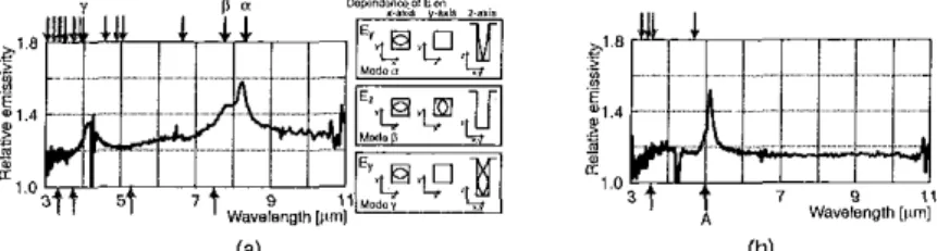
Thermal Emlsslon From Periodic Array of Mlcrocavltles with a Dlfferent Aperture Ratlo
J h i n o r i Kusunoki, lunichi Zhkniiu,u, and Tetsal-o Kobnyarlii, Gradunre Scizool of
Engineeriig Science, Oiuku University, Toyoitnka, Osaka, 560-8531,
lapun
Emnil:llecrnt studies of thermal cnission control have revealed many interesting phenotne~ta.'~'" 'The influence of miccostrucLures upon tlierinal miis- sion, however, h a s iiot well been nndcrstoorl. In this paper, we report expcrimental m d t s of tlxr- mal cmission from a tantaliiin wrfacc having a periodic #may o f microcavitics.
In our experiment, a periodic array of micro- cavities was hbricatcd on the laiilaliitii surface. The schcmzitic drawing of tlie fabricated struc- turc is shown in Fig. 1. Two kinds of structures were fabricated: structore~A
(Ax
= A y = 7.5 p n ,wx
= wv = 5.5 pm), and structure-D (Ax = A, = 5.5 &in, wx = wy = 2.5 pm). Tlrc iipcrlurc ratios are 54% for structure-A and 25% for structurc-D. AQThF13 Fig. 1. Scliematic drawing of idxi- catcd S t I u C t U l e .
rclativc emissivity, wliicli is the ratio of cmissivity of tlie surface with tlir periodic array to that of a
tiat surface, was
me.lsurcd
700 K.Figure 2(a) shows the experimental rcsult Tor structure-A. It is sec" that the effects uf the struc- ture are enhiinccmcnt in emission for the w h ~ l e noticeable pcsks a t 4.15 ptn, 7.71 win, and 8.25 p n . It is known that absorptivity ul ii surface be- comes large wlien the surhcc has roughness, and cmirnivity is equal to absorptivity. l l r u r this is why we have rnhnnced emission. Thc other effect, the timc pcaks, lhas b c w found to be attributcd to electmmagnetic modcs iii ii cavily, as described LlCIOW
The electromsgnetic inode h, hl ( n x , nr, n,) in ti
cavity with onc open end is expresrerl by the fol- lowing equation,
,neasural range ( 3 I""
-
11 pm), and 1hr three~vheii. A is the period of grating, and m, fi = 0,1,2,3,
....
'The periodic array of miccocavilies can be rrgmlrd astwo-dimensional
grating. Thus this phenomenon is also cnpected to occur Cor o u r rxpcrincnt. The upward arrows indiciltc the cslculated positions o i l ; , , . It is clear tliilt the pmsitiun of tlie peak corresponds with one of the wavelengthsh,,
indicated b y the letter A with a,,,(i,01
xSp(o,
i).,ri,is
r c ~ ~ ~ ~ t s u g g m tilllt tilep'
2 '
,a
E -1 4 -2
l , Q A(4
(b) QTuP13'The downward arrow^ indicate tlic calculated positions of
l,,M
and the upwnrdds arrows is fur hsp. Pig. 2. Brperiineiilnl mLllts o f relative cinissiviry for (a) s l ~ u c l u r e ~ A , and (b) StrUCtLtIC-B.cnhanced peak for the structure with a ma11 aperture ratio is attributed to thermally excited SI'I',
In summary. wc liavr rrprrimrntally demon- strated that in the casc o f la.gr ;aperture ratio, the eflect caused by the modes in a cavity becomes dominant, while in the C R S C 01 s t n a l l speruirc ratio, thrmmlly excitcd S I T iias inure influence on 1lrer,nsl CllliSSiOl,.
References
Lio, 1.G. I'lcming, E. Chow, and J. DIW, sinn hy a three~dimrnsional pliotonic V. II 62, 1<2243-2246 (2000). s h i m , A. Ueda, J.'iiikalinra, and T. Kobayashi,'i\n expcrimental sludy of tlmiilal emission from two-dimensional pc- riotlic microstructures:'iii Tectrnicnl Digest of Qanntunr lilrcrmnics m d Laser Scicrice Con- ference (UELS 2001). (Clptical Sociely 01 America, Washington, D.C., ZOUI), pp. 147- 148.
3. S. Meruyama, T. Kashiwa, H. Yugami, snd M.
F.snsl~i,"ll~ermsl radiation from two-dima- sionally confined modes iii Iiiicmctlyitics:) Appl. I'hys. Lctt. 79. 1393-1395 (2001).
nlu,"Cel,,e,,t m t l suppression of t1,ermal
QTuF14
100
pmPhotonlc Band Gap Structures for WDM Appllcatlons
Mehinet Bayindir, S.S. Akarm, and E. Ozbny,
Depnr.tmeitt oJPhyrics, Hilkent University, niikent, 06533 Aaknra, Turkc)i Emmail:
b a y i n d i ~ ~ J ~ ~ . b i l k e ~ ~ t . a l i i . t i
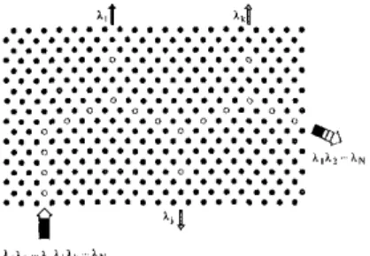
In recent years, tlicre I ~ B I hren tniicli interest in the possible rwlizatiuu "i photonic crystals for designing optical conimnents and circuits. Recently, wc denmnrlratcd a new type of WBYZ-
guiding mechanism, wliicli is 1 " x w as couplcd- cavity w.lveguidcs (CCWs), in which electromag- tictic (EM) wwes can propagate through an array o f coupled cavities' without any radiation losses. In the present work, we pruposc $1 new StruCtLIrc Ihycombininge singlccilvilyandCCWs iorwavc~ length division multiplexing (WUM) sppl- ici%tions. P r w i ~ ~ ~ l y , varions type or photonic
SIIIIC~U~CS have lhecn reported lor WDM applicii-
tions.2.3.4
In order to demonstrate dcmoltiplexing p l i c - nomena in photonic cryslals, we designed a structure in which the coupling lhetwecn the cay- ity mode and tlw guiding mode allows to drop a selective wavelength h, (See Pig. I). 'The sdectiv- ity of dropping wnvelcngtli is dctrmminrd b y local properties of the cavity modes.
We first construclrtl 2D triangular photonic crystals wliicli consist ofdiclcctric cylindrical iilu- mina rods having radius 1.55 inin and refractive index 3.1 nt the mic~.ow~vc freqocncies. 'The lat- tice constant and the corresponding filling frac- tion are a = I.; cm and q '- 0.05, respectively.
Length ofthe lads is I S cm.Thccxperirnfnt,,lsct- up consisted o f a H P fi510Cnetworkanalyneraod micruwsvc horn antennas to mensurc tlie trans- missio,i-amplito~l~ and tlic transmissioii~ptiase properties. 'The cryslal exhibits a photonic band gap extending from 0.7300 to 1. 1400 where 0,:
TUESDAY AFTERNOON
/
QELS 2002
/
85
4. S. Noda, A. ChutirWt, and M. Imada. "liap- ping, and emission
of
photons by a singlc dc- frct in a photonic bniidgap structure:"aturr 407, GO8 (2000).Q h F l 4 Fig. 1. Schematic drawing of tlie proposed deinultiplrxing structure in two-di- memima1 photonic crystals. A sclcctiw wave- length can be dropped lrom the guided modc in. side n coupled-cavity waveguide due to coupling li~twceii the cavity mode and the wwcguidr ,"<>de.
w e measured the trniisinissioii Characteristics corresponding Lo the structure shown iii right panel of Fig. 2. 'I'he CCW is constructed by re- moving 8 rods, and exhibits n waveguiding band exlcnding fiom 1.03& to 1.17hU ( d i d linc). As slrnivn i n Fig. 2 [left panel], photons havingwwe- length h = l.llho is selcctivcly dropped from guiding bond (dotted line).
In coiiclusioni we proposed and demunatrsted a method for adding and dropping of selective wavelength i n photonic crystals. Our results arc iinpcrrtsnt lor designing luture ultrasmnll optics1 ciraiits.
References
I , Mehmet Uayindir, U. Temelkuritn, and E. O~bny, "'llght~binding description of tlie coupled defect modcs in three~dimensinnal photonic crystals:' Phys. Rev, Istt. 84, 2140 2. S. Fan, 1'X Villeneuve, J.D. joannopoulos, and H.A. Haus, 'Y:lrannel d r u ~ tunneling through localized stater," Phys. Rev. k t t . 80, 3. B.B. Nelson, M. Gcrken, I).A.H. Millcr. I<.
Piestun, Chien-Chung Lin, and J.S. Harris, "Use or a dielectric stack as a one-dimrn~ siond ohotonic crvstd for wwelcneth de-
(moo).
960 (1998).
multipleninybybeam shiftiug,"Opt. Lett. 25, 1502
(zona).
Q h l F I 4 Fig. 2. [Left Panel] Mc8sured tllllls-
mission spectra along 1-01 (solid line) and 1-02 (dotted line). [Right I'ancl] Schematics, Lop view oirlie rlrmultiplcxing stiucturc where
(0)
sym- bols dcnote the rrmovcd rodsQTuF15 PO0 pm
Measurement of Optlcal Tunnellng Tlmes In Double-Barrier Photorlc Band Gaps S. Lnnghi,
P
Laportu, Isiituro Nnzionaleperlrr Wrica dell,, Mareria, JXpartirnentu d i Pirim nndCEQSE-UNR, Polileiniro d i M i l a i m Piazza
L.
du Vitici32, 1-20133 M i l a n o i f l d y j , Enioii: [email protected]. itM, Bcbnonte, Ginrinf-Optical Teclinolofier Italia S.p.A., We S n m 222, 1-20126. Milanu (Italy) 'The problem 01. how m u c h time docs B particle spcndrotuiiiirlac~oss .~poteiitinlbnrrierisoncof tlic m n s ~ intriguing problems in qunntrim me^
chanics.' For upsque biwriers, it is knuwvn tlliit the tunneling timc becomes indcpcndcnt of the bar^ rier width (Hartman effect), and may hence imply supcrluminnl prupagation. 'Liinoeling of electromagnetic pulses through photonic barri- ers hits hceii cunsidered as a convenient means for expcrimcntal investigation of tuiinrling owing to the analogy between rlumtum mechnnical and o p t i c a l wave phenomeni. In particular, the expcr- iinrntal validation uf the Hartinanii effect has been reported in tunneling experiments at either microwave and optical wavelengths.'" Tunlieling through dooblc-barrier (DUI photonic barriers shows even a more ammirig phenomenon, namely the independence of the trimit time not only nf lxiiricr width, but also o l barrier separo- tion (genernlizcd Hartmiin cffcct). Meiisureincnts of tnnnelhg times in 1311 structures w c ~ e yrrvi- ously reported in microwwe transmission expcr- imrnts, wlicrc tuiinrling timc measurements arc more acccssible, however 110 crperimrnt has been
pcrformed at optical wwelengths yet. In this work we report on the ineasiirement of tuntieling times in DB photonic harriers, made by two pcriodic librr Hragg gratings (l:l%Gs), at thc wwelength of optical cotnmunicatioiis (1.5
pm),
providing an exprrimental test for the general- ized Hartman effect of quantum nicchmics. Five I)H-FBG s t r w t u m wcrc realized with grating scparsrion L of 18,27,35,42 and 47 min a n c l bilr- rirr width I., 7 8 m m For such stiuctiires, both tiansmissioii spectra and g r o u ~ delays were inra- surrd using a phase shiit tcchniqor; an examplc ol measurcd transmission spectrum and group delay V C ~ S U S frequency for tlie 42-mm separation UU FBG is shown i n Fig. I . Par lrom tlie t'nbry~ Peru1 I C S O I I ~ C C S (off-resonaticc tonneling), the group delay is superluminsl, witli a n expected time edvancemcnt of tlie order of 240-250 ps.Friqiirllry I C I l i l
QTuP15 Fig. 1. Measured spectral power tianmission and group dclay for the Dn-FnG structure ( I , = 42 mm).
Time
[nsl
QTuF15 Fig. 2. Oscilloscope Lraces of off-res- o,,s,,t tUnnFled pulses (1) and rcfcrencr pulses (2).
llariier stparatioil [ m m ] Q'KiiVl5 Dig. 3. 'lhnnelingtime versus barrier separation.
Coi~wrsely, far Irom thc stop band o l tlic Struc~ tule thc group delay corresponds to luminal propagation.
~ i i c c t time-domain meawrcmmts
oi
tonnel- ing delay times wcrc pcrformed in tuinmissinii experiments using a 300 MHz repetition-rate l.3- nr~durarion pulse train, generated from an exter- nally-modulated tunable semiconductor laser. Figurc 2 shows B typical oacilloscopc trace of off- rcsunancr tuiiiiclled pulses [curve ( I ) ] a d w r e ~ sponding trace recorded when the lasei was dc- tuncd away from the stop band of the UU FBG structure [curvc(z)];
a 248 ps peak pulse ad- vancement without appreciable pulse distortion is observed. Time delay measurements werc re- peated for the fivc DB-FUG s t ~ ~ ~ c t u r c s , and the experimental results are summarized it, Fig. 3 and compared with tlte tlieoietiCil1 predictions of t i n - neling times hased on tlie group-dclay analysis of the LIB-FUG structure. 'The diislied line iii the fig- ure shows tlie tliforetical transit tima, from input to output planes, V ~ ~ S U S barricr separation L for pulses tuned far away from tlie band gap of tlic FUG (luminal tiansit times). The solid line is lllc expected transit time for off-resonance tunneling of pulses baaed on tlic group delay analysis. The experimental date (points) are in good ngrecment with tliewrtical prcdictions and Imwc that the tiansit timc doer nut substantially incrcase with b. m : [er seyimtion.1. lI.Y.ChisoandA.M.Steinberg,Prog.Opt. 37, 345 (1997) atid references thercin. 2. A. I l n d r ~ ~ snd G , Nimtz, I'hys. Rev. II 47,
9605 (1993).
3 . A.M. Steinberg,
EL:.
Kwiat and R.Y. Cilia",Phys. Rev. Leu. 71, 708 (1993); Ch. Spiel- maim, R. S,.ipocr, A. Sting1 and P. Krausl, Phys. llev. Lett.73,2308 (1994).