0018-9219 © 2018 IEEE. Personal use is permitted, but republication/redistribution requires IEEE permission. ABSTRACT | Visible light communication (VLC) is an
emerging paradigm that enables multiple functionalities to be accomplished concurrently, including illumination, high-speed data communications, and localization. Based on the VLC technology, visible light positioning (VLP) systems aim to estimate locations of VLC receivers by utilizing light-emitting diode (LED) transmitters at known locations. VLP presents a viable alternative to radio frequency (RF)-based positioning systems by providing inexpensive and accurate localization services. In this paper, we consider the problem of localization in visible light systems and provide an extensive survey of various location estimation techniques, accompanied by discussions of their relative merits and demerits within the context of accuracy and computational complexity. In addition, we investigate a cooperative VLP system architecture in which VLC receiver units are able to communicate with each other for the purpose of cooperation, and present a low-complexity, iterative localization algorithm to demonstrate the benefits of cooperation in VLP systems. Finally, we investigate optimal strategies for power allocation among LED transmitters to maximize the localization accuracy subject to power and illumination constraints.
KEYWORDS | Cooperation; direct positioning; localization; parameter estimation; power allocation; two-step positioning; visible light communication (VLC); visible light positioning (VLP)
I. IN TRODUCTION
Visible light positioning (VLP) systems have recently attracted great attention due to their significant capabilities in localiza-tion related applicalocaliza-tions, especially in indoor scenarios [1], [2]. In indoor environments, VLP systems, combined with the
Digital Object Identifier: 10.1109/JPROC.2018.2823500
power of the light-emitting diode (LED) technology, facili-tate precise and accurate localization and provide low-cost solutions for applications that require compact and effective positioning systems. Due to the emerging developments in the LED technology, LEDs can also be used for commu-nication and localization purposes besides their primary function of providing illumination [3]–[5]. The attractive features of LEDs such as long lifespan and low-power con-sumption make the LED technology the main ingredient in a reliable, robust, and efficient illumination system. In addi-tion to these properties, LEDs have the capability of switch-ing to different intensity levels at very fast rates; that is, they can be modulated at frequencies as high as 300 MHz (much higher than the conventional lighting systems) and can be used to transmit data without causing visible flicker [6], [7]. Hence, LEDs can effectively serve multiple purposes of com-munication and localization as well as illumination.
A. Features of Visible Light Systems
In the context of communication and localization, visible light systems benefit from the desirable proper-ties of the visible light and its spectrum. Compared to traditional wireless systems which employ the cluttered, scarce, and expensive radio frequency (RF) spectrum, VLP systems utilize the visible light portion of the elec-tromagnetic spectrum, which is unlicensed and unregu-lated [4]. The visible light spectrum with its huge license free bandwidth facilitates high speed data transmission and reduces the costs for operators. Besides VLP systems, visible light communication (VLC) systems complement the RF-based communication systems and meet the high-capacity traffic demand for wireless networks by operat-ing in the visible light spectrum [3], [6], [8].
In addition to its untapped spectrum, the LED-based visible light technology provides some advantages for both VLP and VLC systems in terms of reliability, robust-ness, and security [5], [9]. Compared to the transmitters in Manuscript received December 3, 2017; revised February 2, 2018; accepted
March 27, 2018. Date of publication May 11, 2018; date of current version May 24, 2018. (Corresponding author: Sinan Gezici.)
The authors are with the Department of Electrical and Electronics Engineering, Bilkent University, 06800 Ankara, Turkey (e-mail: [email protected]).
Localization via Visible Light
Systems
This paper considers the problem of localization in visible light systems and
discusses localization techniques, cooperative architectures, iterative algorithms,
and optimal power allocation.
conventional RF-based systems, the power consumption of LEDs can be significantly lower. Since LEDs are already used for illumination purposes in indoor environments, they can be incorporated into VLP and VLC solutions without causing a substantial increase in the power consumption. In addition, the inherent line-of-sight (LOS) property of LEDs provides a secure data transmission for systems in which the transmitter and the receiver directly communicate via high-frequency vis-ible light channel in a confined space by ensuring LOS clear-ance between them. The fundamental reason behind that fea-ture is the inability of visible light to penetrate through opaque objects such as walls [10]. That characteristic of the visible light prevents intercell interference issues mostly encountered in RF-based systems and leads to efficient cell-based communica-tion and localizacommunica-tion systems separated by particommunica-tions such as walls [10]. Furthermore, visible light signals do not interfere with the RF signals in sensitive electronic devices and conse-quently they can freely be employed in applications where RF interference may cause issues for proper functioning of devices.
Although global positioning system (GPS) is commonly employed in many applications, it suffers from signal block-age and multipath propagation, which results in poor perfor-mance in indoor environments [11]. For that reason, other RF-based positioning systems are proposed in the literature for indoor applications [12]–[15]. However, those systems can easily be exposed to multipath interference and conse-quently their localization performance can degrade as the radio signals reaching a receiver via different multiple paths (e.g., due to reflections from objects such as walls) complicate the process of estimating location related parameters from the received signal. On the other hand, due to the nature of vis-ible light channels, multipath effects are not as significant in VLP systems as those in RF-based positioning [8], [16]–[21]. Moreover, the widespread use of LEDs for illumination con-stitutes an opportunity to design a ubiquitous and economi-cal positioning system, which functions efficiently in indoor environments [22]. In particular, LED-based VLP systems can easily be integrated into the existing lighting infrastructure (i.e., facilitates the reuse of existing infrastructure) for the purpose of localization in addition to its essential function of illumination without usually requiring rewiring. It is also important to note that VLP systems can be deployed not only for indoor applications but also for outdoor applications such as street lights, stop lights, and airport taxi-way lighting [23], [24]. In general, VLP systems can appropriately be employed in any application where LEDs are utilized.
B. VLP Applications and Design Constraints
VLP systems are used in a broad range of applications including automated vehicles, location-aware services, and asset tracking [1], [23], [25]–[27]. The VLP system employed in each application needs to satisfy different requirements in terms of various criteria such as cost, reliability, and robust-ness. As an example, a VLP system can be installed in a museum and with the help of such a system, the visitors of
that museum can get information about an exhibit (e.g., a his-torical artifact) when they are in front of it. A handheld device (e.g., a smartphone) of a visitor can receive the signals trans-mitted by the LEDs placed near the exhibit and estimate the current position of the visitor. Then, it decides which exhibit the visitor is interested in and informs the visitor about the corresponding exhibit. Such an application may not have a very strict accuracy requirement for localization. However, there also exist applications in which highly accurate and precise positioning is required; e.g., robot navigation [28]. In order to estimate the position accurately and precisely, those applications require more advanced algorithms than those utilized in the museum application, and employ various tech-niques to enhance localization performance of VLP systems.
The design of VLP systems depends also on some crucial factors and constraints arising from the primal illumination purpose of LEDs. The primary function of the LEDs is to provide energy-efficient and high-quality illumination. For that reason, any VLP system designed based on LEDs should be suitable for that purpose and allow the LEDs to operate flawlessly without any restraints. Also, the signals transmit-ted by the LEDs in a VLP system should not cause any vis-ible flicker, and the color changes in the LEDs should not be detectable by the human eye during signal transmission. In addition, a practical VLP system should satisfy lighting level requirements of an illumination system in which dimming control is a required feature. Last, it is worth noting that the relationship between the applied current and the light output of an LED is linear only in a limited dynamic range. Therefore, VLP systems should be designed in consideration of nonlinear characteristics of LEDs, as well [29]–[32].
C. Localization Techniques in VLP Systems
Similar to RF-based positioning systems [33]–[39], VLP systems consist mainly of two components, namely, trans-mitters and receivers. LEDs correspond to the transmitter part of the VLP system and send the necessary information (e.g., a position signal or a code) in order for the receiver to determine its own position in the system. On the receiving side of the VLP system, two different types of receivers can be employed in general [40]–[42], namely, photo detector (PD) and imaging sensor. In both cases, the received signals (i.e., lights) coming from the LEDs are used to estimate the localization parameters such as the relative distance and/ or direction of the LED transmitters. Then, the informa-tion gathered from the received signals is analyzed based on the positioning techniques to figure out the locations of the receivers. Regarding the types of receivers, the PD is a low-cost solution for the receiver part of the VLP sys-tem and provides energy-efficient and high-rate data com-munication. On the contrary, imaging sensors are often more costly and suitable for applications with low data rate requirements [43]. Recently, with improved cost-perfor-mance tradeoffs induced by new complementary metal– oxide–semiconductor (CMOS) technologies, those sensors
can already be found in smart devices such as smartphones and can readily be employed in desired applications [43].
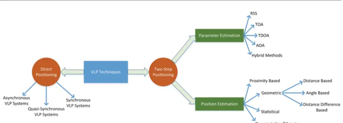
In a VLP system, various approaches can be employed for location estimation, which can mainly be classified into two groups: direct positioning and two-step positioning. In the direct positioning approach, all the available information gathered from the received signals is directly exploited to estimate the position of the receiver without examining position related parameters in advance. In other words, this approach does not include any intermediate steps for parameter estimation and can provide the optimal solution of the localization problem. On the other hand, the two-step method performs position estimation in two separate stages. In the first stage, position related param-eters are extracted, which is followed by estimation of the receiver position in the second stage via various algorithms and methods based on those parameters. The two-step posi-tioning approach has a lower complexity than the direct positioning approach (which requires high data storage and communication capacity); however, it leads to a suboptimal solution as it does not use the received signals directly.
Within the context of two-step positioning, the studies in the literature consider different position related parameters such as received signal strength (RSS) [40], [44]–[46], time of arrival (TOA) [47]–[49], time difference of arrival (TDOA) [50]–[52], and angle of arrival (AOA) [53]–[56]. In VLP sys-tems, RSS is a common parameter which is employed to gather information related to the distance and orientation of the VLC receiver with respect to the LED transmitter. Compared to the time-based parameters such as TOA and TDOA, the RSS parameter can be estimated in a low complexity manner since synchronization is not needed. On the contrary, the VLC receiver must be synchronized with each of the LED transmit-ters in order to estimate the distances between itself and the LED transmitters based on TOA measurements. Regarding the TDOA parameter, there is no need for synchronization between the VLC receiver and the LED transmitters but the LED transmitters must be synchronized among themselves so that the VLC receiver can estimate the distance difference between itself and each pair of LED transmitters based on the corresponding TDOA measurement. Last, AOA is a promising parameter for VLP systems and can efficiently be employed in the localization process. Based on the direction of the received signal, the AOA-based systems can adequately perform locali-zation with the help of LOS connections between the LED transmitters and the VLC receiver.
Although the same types of position related parameters are employed in both VLP- and RF-based localization sys-tems, the information carried by these parameters can be quite different. In particular, the RSS parameter employed in VLP systems has significantly higher accuracy than that in RF-based systems [1]. The main reason for this is related to the severity of multipath effects in RF-based systems. Namely, RF-based systems suffer from multipath interfer-ence and typically do not have an LOS path between the
transmitter and the receiver. On the contrary, multipath effects are not as crucial in VLP systems as those in RF-based ones since VLP systems commonly have LOS paths between LED transmitters and VLC receivers and the diffuse com-ponents arising from multipath scattering are much weaker than the LOS component. Similar to the RSS parameter, the AOA parameter, which is measured based on received power levels at PDs, can also provide high accuracy in VLP systems compared to RF-based solutions for the aforemen-tioned reasons [1]. In addition, it is important to note that RSS and AOA parameters provide a low-cost solution for VLP systems to estimate the position of a VLC receiver accu-rately since they do not require synchronization among VLC units. On the other hand, estimation of TOA and TDOA parameters requires precise synchronization and highly accurate time measurements, thus rendering these metrics relatively costly in practical applications.
After the position related parameters are obtained in the first step of the two-step positioning approach, a VLP system can apply numerous algorithms and techniques in the sec-ond step to finalize the localization process. The algorithms and techniques employed to that aim in the literature can be grouped as follows. First, the proximity-based methods perform localization based on the data obtained from the nearest LED and suits for applications in which very accu-rate position information is not required [57], [58]. Second, the geometric methods determine the position of the VLC receiver by analyzing the position related parameters such as TOA and AOA in a geometric fashion [59], [60]. In other words, the extracted information in the first step is evalu-ated in the second step with the help of some geometric processes such as trilateration and triangulation. The sta-tistical methods, which constitute the third group, benefit from the statistical distributions of the parameters obtained in the first step and derive the position estimators in view of those statistical properties [55], [61]–[64]. Last, in the fingerprinting methods, the estimated parameters based on the online measurements performed by the VLC receiver are compared with the data in a previously obtained data-base and a matching algorithm decides the position of the VLC receiver in the system [65], [66].
Apart from the algorithms and techniques that can be applied in the second step of the two-step positioning scheme, alternative approaches can also be employed to improve the localization performance of VLP systems [67]–[69]. As in RF-based positioning systems [34], [70]–[72], cooperation among the entities in a VLP system can enhance the accu-racy of localization [67], [68]. Moreover, the optimal power allocation approaches can be designed for LED transmitters to enhance the localization accuracy of the VLP system [69]. In these approaches, the powers of the LEDs in the system can be set to the optimal levels instead of operating all the LEDs at the same power level while taking power and illu-mination constraints into account during the design of the system.
D. Summary and Organization
In general, the aim of this paper is to provide an overview of the position estimation methods for VLP systems. The main points presented in the paper can be summarized as follows.
• We present the state-of-the-art methods for position estimation in visible light systems, which can essen-tially be classified as direct and two-step approaches. • We investigate different types of position related
parameters employed in VLP systems, such as RSS, TOA, TDOA, and AOA, and focus on positioning tech-niques that utilize those parameters.
• We discuss the effects of cooperation on the per-formance of VLP systems and present an iterative-gradient-projection-based cooperative localization algorithm, motivated by a quasi-convex feasibility approach.
• We study the problem of optimal power allocation among LED transmitters to maximize the localiza-tion performance under practical constraints (e.g., illumination) and illustrate the resulting accuracy improvements.
The remainder of the paper is organized as follows. Section II presents position estimation methods for VLP systems. In Section III, positioning techniques are discussed in the presence of cooperation among the entities in a VLP system. Section IV investigates the optimal power allocation problem for LEDs in a VLP system in consideration of illu-mination constraints, and then provides numerical exam-ples for the solutions of the optimization problems. Finally, Section V concludes the paper and addresses some possible directions for future work.
II. POSITION ESTIM ATION METHODS
In this section, we discuss various positioning schemes for VLP systems to present a comprehensive insight on the state-of-the-art techniques for parameter extraction and
position estimation (see Fig. 1). In both RF- and VLC-based systems, position estimation is performed by exchang-ing signals between nodes with known locations (called anchor/reference nodes) and nodes whose locations are to be estimated (called target/agent nodes) [37], [61]. (Also, signal exchanges among target nodes can provide additional location information, which is utilized in cooperative posi-tioning systems; see Section III.) For VLP systems, LED transmitters, which have known locations and are typically attached to the ceiling of a room in indoor scenarios, func-tion as anchor nodes, and VLC receivers, equipped with PDs, seek to determine their own locations based on signals transmitted by LEDs and detected through PDs.1 Hence,
VLC receivers commonly perform self-localization [81] by utilizing incoming VLC signals and known locations of LEDs that emit those signals. In the following, we focus on the two well-known positioning paradigms, namely, direct positioning and two-step positioning. Direct positioning consists of a single step for location estimation while two-step positioning is conducted in two separate phases [61], [63], [82]–[84], as detailed in the following sections.
A. Direct Positioning
In the direct positioning approach, localization relies on a single-step estimation procedure that utilizes the entire received waveforms to infer the location of a target node [61], [81], [82], [85]. As opposed to the conventional two-step approach, the direct positioning technique exploits the whole received signals to estimate the location with-out intermediate steps for extracting location-dependent parameters [61], [82]. The direct positioning method has successfully been applied to both RF- [82]–[88] and VLC-based [63], [89] localization systems. To investigate the
1In this paper, PD-based VLC receivers are considered for VLP
systems. For imaging-sensor-based VLP systems, see [41], [42], and [73]– [76]. The reader is referred to [25], [26], [46], and [77]–[80] for some practical implementations of VLP systems.
direct positioning approach in VLP systems, we describe the signal model at a VLC receiver, present the direct-posi-tioning-based maximum-likelihood (ML) estimators, and provide performance limits for localization in the following sections.
1) Received Signal Model: Consider a VLP system
with N L LED transmitters and a VLC receiver. Assuming a
LOS scenario between each LED transmitter and the VLC receiver [1], [47], the received signal at the PD of the VLC receiver due to the i th LED transmitter can be expressed as [47]
r i (t) = α i R p s i (t− τi )+ η i (t) (1) for i ∈ {1, . . . , N L } and t ∈ [ T 1,i , T 2,i ] , where T 1,i and T 2,i
deter-mine the observation interval for the signal emitted by the
i th LED transmitter, α i is the optical channel attenuation
between the i th LED transmitter and the VLC receiver ( αi > 0 ), R p denotes the responsivity of the PD, s i (t) is the transmitted signal of the i th LED transmitter, which is nonzero over an interval of [0, T s,i ] , τ i is the TOA of the signal emitted by the i th LED transmitter at the VLC receiver, and η i (t) is zero-mean additive white Gaussian noise with spec-tral density level σ 2 . To facilitate independent processing of signals coming from different LED transmitters, a type of multiple-access scheme, such as frequency-division or time-division multiple access [90], [91], can be employed. Hence, the signals corresponding to different LED transmitters do not interfere with each other at the VLC receiver, and the noise processes η 1 (t) , . . ., η N L (t) become independent.
Let l r = [ l r,1 l r,2 l r,3 ] T and l it = [ l t,1i l it,2 l t,3i ] T denote,
respectively, the locations of the VLC receiver and the
i th LED transmitter, and
‖
l r − l ti‖
represent the distancebetween the i th LED transmitter and the VLC receiver. Then, the TOA parameter in (1) can be modeled as
τi =
‖
l r − l ti
‖
______c + Δ i (2)
where c is the speed of light, and Δ i denotes the time off-set between the clocks of the i th LED transmitter and the VLC receiver. In synchronous VLP systems, where all the LED transmitters and the VLC receiver are synchronized to a common clock, Δ i = 0 for i = 1, . . ., N L . In asynchronous
systems, synchronization exists neither among the LED transmitters nor between the LED transmitters and the VLC receiver, in which case Δ i ’s can be modeled as deterministic unknown parameters. Finally, for quasi-synchronous VLP systems [92], where the LED transmitters are synchronized to a common time reference but are not synchronized with the VLC receiver, Δ i = Δ for i = 1, . . ., N L .
Based on the Lambertian model [93], the optical chan-nel attenuation α i in (1) can be expressed as
α i = ( m i + 1) A R cos m i ( φ i ) cos ( θ i ) ____________________ 2π‖ l r − l ti ‖ 2 (3)
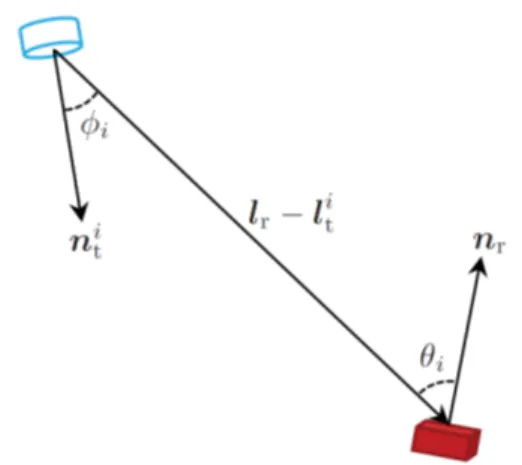
where m i is the Lambertian order for the i th LED transmit-ter, A R is the area of the PD at the VLC receiver, and φ i and θ i are the irradiation and the incidence angles, respectively, between the i th LED transmitter and the VLC receiver [46], [47]. From the definitions of φ i and θ i (see Fig. 2), (3) can be rewritten as α i = − ( m i + 1) A R [
(
l r − l ti)
T n ti ] m i(
l r − l ti)
T n r ________________________ 2π ‖ l r − l ti ‖ m i +3 (4) where n r = [ n r,1 n r,2 n r,3 ] T and n it = [ n t,1i n t,2i n t,3i ] T stand for the orientation vectors of the VLC receiver and the i th LED transmitter, respectively [47], [55].It is assumed that the parameters A R , R p , n r , m i , l ti , and n ti ,
and the transmitted signals s i (t) for i = 1, . . ., N L are known
by the VLC receiver [55], [63].
Remark: It is important to emphasize that the signal
model in VLP systems differs from the one in RF-based localization systems since the intensity of the electromag-netic waves is modulated in VLP systems instead of the field of the wave, which is employed in RF-based localization sys-tems [47]. Therefore, unlike in RF-based syssys-tems, the trans-mitted signal in VLP systems cannot be negative. Hence, the design of modulation techniques to be employed in VLP sys-tems necessitates the consideration of optical signal proper-ties together with illumination constraints. In addition to modulation techniques, VLP- and RF-based systems differ in the channel model, as well. In VLP systems, the optical channel model is considered, which significantly depends on the orientations of the LED transmitter and the VLC receiver, and the area of the PD at the VLC receiver besides the locations of the VLC receiver and the LED transmitter.
2) Direct-Positioning-Based ML Estimators: The
ration-ale behind the use of direct positioning is to estimate the VLC receiver location l r by exploiting all the available information
about l r , i.e., the received signals { r i (t)} N i=1L in (1). In this way, the information loss stemming from intermediate steps (cf., Fig. 2. Illustration of configuration parameters in the Lambertian model, where the cylinder represents the i th LED, and the rectangular prism denotes the PD.
Section II-B) can be avoided and the location can be estimated in an optimal manner. In the following, the direct-position-ing-based ML estimators are investigated for synchronous, quasi-synchronous, and asynchronous VLP systems.
• Direct positioning in synchronous systems: Since
Δ i = 0 in (2) for synchronous systems, the ML
estima-tor for l r can be obtained from (1) as [63]
ˆ l r DP,syn = arg max l r ∑ i=1 N L α i ∫ T T 1,i2,i r i (t) s i (t − τ i )dt − __ R p 2 ∑ i=1 N L α i2 E 2i (5)
where E 2i is the electrical energy of s i (t) , defined as E 2i ≜ ∫
0 T s,i ( s i (t)) 2 dt. (6)
The direct estimator in (5) performs a search over all possible values of the unknown location l r via its
rela-tion to τ i in (2) (with Δ i = 0 ) and to α i in (4).
• Direct positioning in quasi-synchronous systems: As the LED transmitters are synchronized to a common time base in quasi-synchronous systems, the time off-sets in (2) are the same among the LED transmitters, i.e., Δ i = Δ for i = 1, . . ., N L , where Δ is an unknown
time offset. Under this setting, the direct-positioning-based ML estimator is given by [94]
(l ˆ r DP,qsy , Δ ̂ ) = arg max ( l r ,Δ) ∑ i=1 N L α i ∫ T 1,i T 2,i r i (t) s i (t − τ i )dt − R __2p ∑ i=1 N L α i2 E 2i (7)
where E 2i is as defined in (6). Since the time off-
set Δ between the receiver and the transmit-ters is unknown, a joint search over l r and Δ
must be performed in (7) to find the optimal l r .
Note that α i in (7) depends on l r via (4), while τ i is a
function of both l r and Δ via (2) (with Δ i = Δ for i = 1,
. . . , N L ).
• Direct positioning in asynchronous systems: For asynchronous systems, the time offset Δ i in (2) is an unknown parameter. In this case, the ML estimator is obtained as [63] ˆ l r DP,asy = arg max l r i=1∑ N L (α i C ̃ rsi − 0.5 R p α i2 E 2i ) (8)
where E 2i is given by (6) and
C ̃ rsi ≜ max τ i ∫ T 1,i
T 2,i r
i (t) s i (t − τ i )dt. (9) As observed from (8), the direct estimator in asyn-chronous systems attempts to determine the location of the VLC receiver based on its relation with the channel attenuation factor in (4). This is due to the
fact that no information about l r can be extracted from
τ i ’s in (2) due to the unknown time offsets in the
asyn-chronous case. For this reason, the resulting estima-tor in (8) employs the correlaestima-tor peak in (9) [cf., the integral expression in (5)] and utilizes the relation of
l r to α i ’s only.
The direct positioning estimators in (5), (7), and (8) constitute the optimal estimators (in the ML sense) for the location of the VLC receiver. However, the direct position-ing paradigm may have several drawbacks, includposition-ing high computational burden [63] and excessive data storage and communication concerns.
Remark: In addition to their utilization in VLP
sys-tems, direct localization algorithms have also been widely used for RF-based localization systems in the literature [82]–[88]. A common observation in RF and VLP systems regarding the performance of direct position estimation is that the improvement in localization accuracy provided by direct positioning over its two-step counterpart2 is par-ticularly significant in the low signal-to-noise ratio (SNR) regime [63], [82], [83], [85], [86], [88], [94]. The major difference between these two systems lies in the fact that different types of signal metrics are employed for posi-tion estimaposi-tion. In particular, both signal-strength-based (i.e., α i ) and time-based (i.e., τ i and Δ ) information are utilized for direct positioning in synchronous and quasi-synchronous VLP systems, as seen from (5) and (7). On the other hand, received powers of RF signals can severely be affected by multipath and shadowing effects [95]; hence, they cannot be used reliably in RF-based direct positioning algorithms. Hence, in general, direct localiza-tion approaches in RF systems consider either synchro-nous [82]–[85] or quasi-synchrosynchro-nous [83], [87] scenarios. However, for VLP systems, direct position estimation can be performed also for asynchronous scenarios since the Lambertian model in (3) can accurately characterize the optical channel attenuation [8].
3) Performance Limits: Theoretical performance limits
provide essential guidelines for the design and evaluation of practical VLP systems. In this part, we present the Cramér– Rao lower bound (CRLB) on variances of unbiased estimates of l r in synchronous, quasi-synchronous, and asynchronous
VLP systems. The localization accuracy limits characterized by the presented CRLBs are attainable by the correspond-ing ML estimators in (5), (7), and (8) at high SNRs and/or bandwidths [96], [97].
• CRLB in synchronous systems: The CRLB for localiza-tion of the VLC receiver in synchronous VLP systems is expressed as [63]
𝔼 {‖ ˆ l r − l r ‖ 2} ≥ trace { J syn−1 } (10)
2See Section II-B for detailed treatment on two-step positioning
where ˆ l r represents an unbiased estimate for the
loca-tion l r and the Fisher information matrix (FIM) J syn is
calculated from [ J syn ] k 1 , k 2 = R p2 ___ σ 2 i=1∑ N L ( E 2i ____∂ α i ∂ l r, k 1 ____∂ α i ∂ l r, k 2 + E 1i α i2 ____∂ l ∂ τ i r, k 1 ____∂ τ i ∂ l r, k 2 − E 3i α i ( ∂ α i ____ ∂ l r, k 1 ____∂ τ i ∂ l r, k 2 + ____∂ τ i ∂ l r, k 1 ____∂ α i ∂ l r, k 2 )) for k 1 , k 2 ∈ {1, 2, 3} . In (11), ∂ αi / ∂ l r,k and ∂ τ i / ∂ l r,k are,
respectively, the partial derivatives of the channel attenuation in (4) and the TOA parameter in (2) (for Δ i = 0 ) with respect to l r,k , E 2i is given by (6), and E 1 i
and E 3i are defined as
E 1i ≜ ∫ 0 T s,i ( s ′ i (t)) 2 dt (12) E 3i ≜ ∫
0 T s,i s i (t) s ′ i (t) dt (13)
with s ′ i (t) denoting the derivative of s i (t) .
• CRLB in quasi-synchronous systems: In quasi-syn-chronous VLP systems, the CRLB for location estima-tion of the VLC receiver is expressed as [94]
𝔼 {‖ ˆ l r − l r ‖ 2 } ≥ trace{ J qsy−1 } (14) where J qsy = J syn − _________∑ 1 i=1 N L E 1 i α i2 ν ν T (15) with J syn being given by (11), ν = [ν1 ν2 ν3 ] T , and
ν k ≜ R __σp ∑ i=1 N L
(
E 1i α i2 ____∂ l ∂ τ i r,k − E 3 i α i ____∂ l ∂ α i r,k)
(16) for k ∈ {1, 2, 3} .• CRLB in asynchronous systems: For asynchronous VLP systems, the CRLB is stated as [55], [63]
𝔼 {‖ ˆ l r − l r ‖ 2} ≥ trace { J asy−1 } (17)
where the FIM is calculated from [ J asy ] k 1 , k 2 = R p2 ___ σ 2 i=1∑ N L ( E 2i − ( E 3 i ) 2 ____ E 1i ) ∂ α i ____ ∂ l r, k 1 ____∂ α i ∂ l r, k 2 (18) for k 1 , k 2 ∈ {1, 2, 3} .
It is noted that the transmitted signals s i (t) affect the FIM expressions in (11), (15), and (18) via E 1i , E 2i , and E 3i ,
and the contribution of the system geometry to the FIM is through the ∂ α i / ∂ l r,k and ∂ τi / ∂ l r,k terms. In addition, the
∂ τi / ∂ l r,k terms do not appear in (18) since the TOA
param-eter does not provide location related information in asyn-chronous systems.
Based on the CRLB expressions, some practical sce-narios can be investigated to gain insights into the locali-zation performance of VLP systems with varying levels of
synchronism. In particular, the following practical assump-tions are considered: 1) E 3i = 0 for i = 1, . . ., N L , which is
the case for most practical pulses,3 and 2) the transmitted signals s i (t) are identical, i.e., s i (t) = s(t) . (In this case, the parameters related to the pulse shape are the same for all the LED transmitters, i.e., E i1 = E 1 , E i2 = E 2 , and E 3i = E 3 for
i = 1, . . ., N L .) Then, it follows from (15) that
J syn − J qsy = R p 2 E 1 ____ σ 2 ϑ ϑ T (19)
where ϑ = [ ϑ 1 ϑ 2 ϑ 3 ] T with ϑ k ≜ ∑i=1 N L α i2 (∂ τ i / ∂ l r,k )/
√
_______ ∑i=1 N L α i2 for k ∈ {1, 2, 3} . From (19), it is clear that J syn ≽ J qsy is alwayssatisfied since E 1 is positive by definition, where J syn ≽ J qsy
means that J syn − J qsy is positive semidefinite. Therefore, it
is deduced from (10) and (14) that synchronism between the LED transmitters and the VLC receiver helps achieve a reduced CRLB (that is, improved localization performance), as expected. In addition, based on Parseval’s relation [48]
E 1 = 4 π 2 β 2 E 2 (20)
where β denotes the effective bandwidth of s(t) ,4 it can be inferred from (19) that the information gain via synchro-nism becomes more significant as β gets larger. Similar to (19), a relation between the FIMs of quasi-synchronous and asynchronous systems can be derived as
J qsy − J asy = R p2 E 1 ____ σ 2 ( ( ∑ i=1 N L α i2 μ i μ Ti ) − _______∑ 1 i=1 N L α i2 ~ μ ~ μ T ) (21) where μ i = [μi,1 μ i,2 μ i,3 ] T , ~ μ ≜ ∑ N i=1L α i2 μ i , and μ i,k ≜∂ τi / ∂ l r,k . It follows from the Cauchy–Schwarz inequality that J qsy ≽ J asy .
Based on (21), similar conclusions to those related to (19) can be made. Namely, as the effective bandwidth increases, the accuracy of (quasi-)synchronous positioning improves. This suggests that using LEDs with optical clock rates up to 120 MHz [98], very precise position estimates can be obtained in (quasi-)synchronous VLP systems. However, for VLP signals with relatively low effective bandwidths and/ or in the presence of imperfect synchronization, asynchro-nous VLP systems would be more preferable due to their low complexity.
B. Two-Step Positioning
As the most prevalent approach for positioning in VLP systems, the two-step method first extracts position related parameters from the received VLC signals and then performs position estimation based on those parameters. Compared to direct positioning, the two-step approach leads to low computational complexity as it utilizes only a subset of the available information (i.e., position-dependent parameters) for positioning instead of the entire received signals [63]. (11) 3 E 3 i is calculated from (13) as E 3 i = ( s
i ( T s,i ) 2 − s i (0) 2 ) / 2 , which is zero
for practical pulse shapes (e.g., [47, eq. (3)]).
4β is defined as β =
√
_______________ (1 / E2 ) ∫ f 2 |S(f ) | 2 df with S(f) representing the
Hence, a certain level of accuracy is sacrificed for the sake of a reduced computational burden in two-step positioning. In the following, we first describe the commonly employed position-dependent parameters in the first step and how to estimate them in an optimal manner. Then, we present posi-tion estimaposi-tion techniques that employ those parameters in the second step to obtain an estimate of the VLC receiver location.
1) Parameter Estimation: Estimation of
position-dependent parameters in a VLP system is carried out as the first step of a two-step positioning method. This part will focus on the most common parameters used in the first step of VLP algorithms, including RSS, TOA, TDOA, and AOA, and also present hybrid algorithms that utilize a combina-tion of those parameters.
a) Received Signal Strength: The RSS estimate
(meas-urement) obtained from the received VLC signal contains positional information as the channel attenuation fac-tor5 in (4) depends on the location l r of the VLC receiver.
According to the Lambertian model in (4), which charac-terizes the level of attenuation in visible light channels, the received signal gets weaker as the distance between the LED transmitter and the VLC receiver increases or as the displacement vector l r − l ti deviates from the
orien-tation of the LED transmitter and/or the VLC receiver. In practical VLP systems, RSS-based positioning is a common technique due to its low-cost hardware implementation that requires no synchronization, as opposed to TOA-based schemes [44]–[46]. In addition, multipath effects in indoor visible light channels are not significant as compared to RF propagation, which makes the Lambertian formula a reliable model for quantification of channel attenuation [16]–[18], [8, Sec. 3.4.1].6 Therefore, RSS has been a popu-lar discriminative feature for positioning in visible light sys-tems [40], [44]–[46], [64], [100]–[103].
For an asynchronous VLP system, the ML estimate α̂ i of the RSS parameter αi corresponding to the i th LED trans-mitter can be obtained from the received signal in (1) as
α̂ i = ____ C ̃ rsi
R p E 2i (22)
if C ̃ rsi ≥ 0 ( α̂ i = 0 otherwise), where C ̃ rsi and E 2i are given
by (9) and (6), respectively [63]. From (22), it is observed that the RSS parameter corresponds to a scaled version of the measured energy at the VLC receiver as C ̃ rsi rep- resents the peak value of the correlator output in (9) (obtained by correlating the received signal with delayed replicas of the transmitted signal). After obtaining the RSS
estimates { α̂ i } i=1 N L in the first step, a two-step algorithm can use them as an input to the second step to estimate the VLC receiver location.
Since the orientations of the LED transmitters and the VLC receiver (denoted by n ti and n r , respectively) affect
the RSS measurement in (4), the estimated RSS value can-not directly be translated to a distance estimate in general. However, in certain practical scenarios, distance information can unambiguously be obtained from the RSS estimates. For example, consider a VLP scenario in which the LED trans-mitters are pointing downwards (i.e., n ti = [0 0 − 1] T ), the
VLC receiver is pointing upwards (i.e., n r = [0 0 1] T ), and
the height of the VLC receiver is known (that is, the receiver moves on a horizontal plane and performs 2-D localization) [45], [47]–[49], [64], [100], [101]. Then, the RSS parameter in (4) can be expressed as
α i = ___________( m i + 1) A R h i m i +1
2π d i m i +3
(23)
where h i is the height of the i th LED transmitter with respect to the VLC receiver and d i = ‖ l r − l ti ‖ is the distance
between the i th LED transmitter and the VLC receiver. Based on the relation (23), the distance estimate d ̂ i can be calculated from the RSS estimate α̂ i [40], [48], which can then be utilized in a trilateration algorithm to get the final position estimate [18], [44], [45], [104].
The accuracy of RSS information can be quantified by theoretical performance limits to explore the best achiev-able estimation performance. The CRLB on the variance of an unbiased estimate α̂ i of the RSS parameter α i can be expressed as [63] 𝔼{ ( α̂ i − αi ) 2} ≥ __________ E 1i E 1i E 2i −
(
E 3i)
2 σ 2 ___ R p2 (24)where E 1i , E 2i , and E 3i are given by (12), (6), and (13), respec-
tively. As noted from (24), the performance of RSS estima-tion deteriorates with an increase in the noise level in the received signal in (1). In addition, as the electrical energy
E 2i of the transmitted signal increases, the RSS information
becomes more accurate due to more favorable SNR condi-tions. Moreover, the accuracy of RSS estimates improves for larger values of the responsivity R p of the PD, since respon-sivity, defined in terms of amperes per watt, measures the conversion efficiency of incident optical power to electrical current [93].
For scenarios in which the RSS-distance transformation can explicitly be performed [as in (23)], the CRLB for RSS-based distance estimation can be obtained as [48], [101] 𝔼
{
( d ̂ i − d i ) 2}
≥ E 1 i __________ E 1i E 2i −(
E 3i)
2 ( 2πσ d i3 _____ R p A R ) 2 × ____________1 ( m i + 1) 2 ( m i + 3) 2(
d i __ h i)
2 m i +2 (25) 5In this paper, the RSS parameter refers to the channel attenuationfactor α i since α i is nonnegative and the received signal energy is
deter-mined by 6 α i [63].
Multipath effects can significantly be mitigated by employing cali-bration techniques, such as selecting a subset of LEDs and using a dense LED configuration [99].
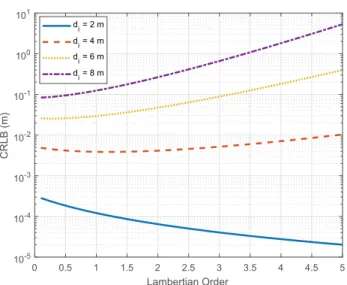
where d ̂ i denotes an unbiased estimate of d i . From (25), it is observed that when d i ≈ h i , that is, when the VLC receiver is almost directly under the LED, the CRLB decreases with an increasing Lambertian order m i since the sensitivity of RSS to distance becomes more pronounced for larger values of m i in such cases. More specifically, considering the fact that the directivity of an LED is determined by the Lambertian order (more directive for larger orders), the Lambertian pattern in (23) is more sensitive to distance (or, angle7) around the peak point of the pattern for higher levels of directivity. On the other hand, when d i ≫ h i , the accuracy of distance esti-mation improves as the Lambertian order decreases since more signal power can be received at longer distances if the LED is not very directive. These remarks are illustrated for an example scenario in Fig. 3, where h i = 2 m, E 2i = 2 . 25 ×
10 −4 W, E 3i = 0 , σ 2 = 1 . 3381 × 10 −22 W/Hz, R p = 0 . 4 A/W, and A R = 10 −4 m 2 in (25) (the same parameters as in [48]
with a source optical power of 1 W).
b) Time of Arrival: The distance between an LED
transmitter and a VLC receiver can be calculated based on the time of flight of the signal between the two devices, which is determined by the TOA parameter as defined in (2). The primary requirement for the utilization of TOA information in VLP systems is that the clocks of the LED transmitters and the VLC receiver must be synchronized [47]. In the case of synchronization, the VLC receiver can estimate the TOAs of the incoming signals from mul-tiple LEDs and accomplish position estimation based on these TOA (equivalently, distance) estimates. Due to the increased cost of implementation associated with clock synchronization, the research on TOA-based positioning is fairly limited [47]–[49], [63].
The TOA parameter can be estimated from the received VLC signal in (1) as [48], [63] τ̂ i = arg max τ i ∫ T 1,i T 2,i r i (t) s i (t − τi )dt (26) where τ̂ i is the ML estimate of the TOA parameter τ i . As observed from (26), the optimal ML TOA estimation is achieved by the correlation (matched filter) receiver [105]. That is, the TOA between the transmitter and the receiver is estimated by performing correlation of the received VLC signal with delayed copies of the transmit signal and identifying the location at which the peak occurs.
The CRLB for distance estimation based on TOA infor-mation in synchronous VLP systems is stated as [47], [48] 𝔼
{
(
d ̂ i − d i)
2}
≥ E 2 i __________ E 1i E 2i −(
E 3i)
2 ( _____ R σ c p α i ) 2 (27) where d ̂ i represents an unbiased estimate of distance d i between the i th LED transmitter and the VLC receiver, andc is the speed of light. It is noted from (27) that the accuracy
of TOA estimation increases with the SNR [cf., the signal model in (1)]. In addition, for E 3i = 0 , the lower bound in
(27) reduces for larger effective bandwidths via (20). As opposed to the TOA-based method, the effective bandwidths β i ’s have no effects on the CRLB of RSS-based distance esti-mation in (25) for E 3i = 0 . Therefore, synchronous VLP
sys-tems exploiting high-bandwidth LEDs offer the potential of high accuracy distance estimation.
c) Time Difference of Arrival: TDOA-based
position-ing exploits the differences between the distances from multiple LED transmitters to the VLC receiver. The TDOA parameter can be obtained by taking the difference of two TOA measurements corresponding to two different LEDs as
Δ τ̂ ij = τ̂ i − τ̂ j (28) where Δ τ̂ ij denotes the TDOA estimate between the i th and j th LEDs, and τ̂ i is the TOA estimate for the i th LED as in (26). Considering the TOA model in (2), the TDOA parameter in the noiseless case can be modeled as follows: Δ τ ij =
‖
l r − l t i‖
______ c −‖
l r − l t j‖
______ c + Δ i − Δ j . (29) In the presence of synchronization among the LED transmitters (i.e., Δ i = Δ for i ∈ {1, . . . , N L } ), the TDOAinformation in (29) characterizes the difference in the TOA values belonging to the two LEDs since the constant time offsets are removed via subtraction. Hence, utilizing TDOA measurements requires that the LED transmitters be syn-chronized to a common time reference [106]. However, as opposed to TOA-based positioning, no synchronization is required between the LED transmitters and the VLC 7For 2-D scenarios, irradiation angle ϕ
i can be converted to distance
by d i = h i / cos ϕ i , where h i is the known height of the LED with respect to
the receiver.
Fig. 3. The square root of the CRLB expression in (25) versus the Lambertian order m i , for various values of distance d i .
receiver, thereby making TDOA a relatively less expensive method for VLP systems [106].
Besides the TDOA estimation method in (28), the cross correlation of the two received signals can be performed to estimate the TDOA parameter as follows [50], [51]:
Δ τ̂ ij = arg max Δ τ ij ∫ T 1,ij
T 2,ij r
i (t) r j (t + Δ τ ij ) dt (30) where T 1,ij and T 2,ij specify the complete observation
interval corresponding to the signals emitted by the i th and j th LEDs. Another method for measuring the range differences between LEDs is to utilize different carrier frequencies for the transmit signals s i (t) belonging to dif-ferent LEDs [26], [52], [107]. In this way, phase differ-ences between the received signals can be converted to distance differences [52]. Moreover, TDOA can also be calculated by using the same carrier frequency with dif-ferent phase shifts for s i (t) ’s [108].
d) Angle of Arrival: The information regarding the
AOA of VLC signals incident upon the PD of the VLC receiver can be exploited to determine the position of the VLC receiver. Specifically, with the knowledge of the posi-tions and the orientaposi-tions of LED transmitters, the AOA (i.e., the incidence angle) of a signal arriving at a PD yields a unique angle of departure (AOD) (i.e., the irradiation angle) from the LED that emits that signal. In the ideal case of noiseless AOA/AOD estimation, the intersection point of the lines extending from multiple LEDs in the directions of the corresponding AOD estimates would coincide with the location of the VLC receiver [55], [60], [109]. Hence, VLP systems can take advantage of the AOA parameter for loca-tion estimaloca-tion.
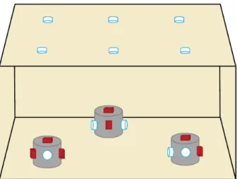
One way to estimate the AOA parameter is via the LED connectivity information, which can be acquired by deploying multi-LED visible light access points (VAPs) in an indoor scenario [55], [60]. Each VAP can be designed to contain multiple LED transmitters with very narrow field of views, whose orientations are adjusted such that every point in the room gathers a signal only from a single LED [60, Fig. 1]. For such a configuration, the receiver is connected to a single LED of each VAP, which characterizes the AOA information gathered from that VAP via the orientation of the designated LED.
Another method for AOA estimation is to use an array of PDs in the VLC receiver [53], [54], [110], [111]. For instance, the differences in RSS measurements at the PDs arranged in a circular layout on the VLC receiver can be uti-lized to estimate the AOA of the signal at the receiver [53]. It is also possible to use a uniform linear array (ULA) of PDs to determine the direction of arrival of the VLC signal via a beamforming vector [54], [110]. To increase the sen-sitivity of received powers at PDs to the direction of signal arrival, a reasonable approach is to employ aperture-based
receivers where an opaque aperture containing a hole is placed on top of each PD in a circular array [56], [111]. In such configurations, the holes on the apertures are shifted from the location of PDs toward the center of the circular array [111, Fig. 1] to enlarge the relative differences in the measured signal powers at PDs, resulting in more accurate AOA estimates.
Similar to array configurations, the VLC receiver struc-tures involving multiple PDs with different orientations can be employed to obtain AOA information from the received signals [109], [112]–[115]. Using a corner-cube structure that involves three PDs with orthogonal detec-tor planes, AOA estimation can be performed by measuring the difference in signal powers received at the PDs [109], [115]. Similarly, multiple tilted PDs on a VLC receiver can reveal information about the direction of arrival of incom-ing signals via the differences of RSS measurements at the PDs [112]–[114].
e) Hybrid Approaches: In addition to parameter
estima-tion methods that utilize only a single property of received VLC signals (e.g., TOA, RSS, or AOA), there exist hybrid schemes that aim to estimate position-dependent param-eters through joint utilization of several signal attributes [48]. Such hybrid approaches are likely to produce more accurate first-step parameter estimates compared to con-ventional techniques by blending the benefits of each signal characteristic into a unified estimation framework.
As discussed previously, both TOA and RSS measure-ments can provide information for distance estimation in VLP systems. Hence, an ML-based distance estimator that incorporates information from both time delay (i.e., TOA) and optical channel attenuation (i.e., RSS) param-eters can be designed to improve the accuracy of ranging in a synchronous scenario [48]. For such an estimator, the information obtained from the TOA parameter gets more significant as the effective bandwidth of the signal increases. For small effective bandwidths (around for 1 MHz or lower), the additional information from the TOA parameter becomes negligible compared to the informa-tion obtained from the RSS parameter; hence, synchro-nism does not provide significant performance benefits in such scenarios (since RSS can also be estimated in asyn-chronous systems) [48].
2) Position Estimation: As the second step of a two-step
positioning algorithm, the position estimation procedure takes as input the position related parameters from the first step and outputs the estimated position of the VLC receiver. In this part, we discuss four different classes of position estimation methods, namely, proximity-based methods, geometric methods, statistical methods, and fingerprinting/ mapping methods.
a) Proximity-Based Methods: Proximity-based position
thus has the advantage of being computationally efficient. In a proximity-based positioning scheme, the VLC receiver extracts from the received signals the identification data of the nearest LED8 and relays it to a central database, which transmits the LED position information corresponding to that identification back to the receiver [1], [57], [58], [116]. As an alternative approach, LED transmitters may broadcast their positions instead of their identities, which circumvents the need for communications with the data-base [1], [58]. As the result of this process, the VLC receiver acquires the location of the closest LED, which provides a rough location information (i.e., the receiver lies in the area spanned by the field of view of the specified LED transmit-ter). Therefore, the accuracy of proximity based positioning is primarily affected by how dense the LEDs are deployed over the ceiling of the indoor environment in which the receiver operates [64].
Proximity-based localization is particularly useful for applications where accuracy requirements are not strict, such as asset tracking in hospitals and location-aware ser-vices in art galleries [1]. However, certain applications, such as mobile robot navigation, may require more pre-cise location information than that provided by the prox-imity-based method [1]. In order to alleviate this problem, angular information obtained from auxiliary sensors can be combined with the proximity-based information to refine the coarse position estimates [117]. In addition, a biconvex lens can be inserted under each LED luminary containing multiple LED transmitters to improve the accuracy of proximity-based positioning by providing angular diversity [118].
b) Geometric Methods: Geometric techniques exploit
the geometric interpretations of the first-step parameter estimates to obtain the position of the VLC receiver. In the following, we elaborate on how geometric properties of measurements related to distance (TOA/RSS), angle (AOA), and distance difference (TDOA) can be utilized for localization.
• Distance-based geometric localization: In geo-metric position estimation, a distance estimate between an LED transmitter and the VLC receiver, which can be derived from TOA and/or RSS meas-urements,9 delineates a sphere around the LED transmitter corresponding to possible locations of the VLC receiver. Based on distance measurements from four (three) LEDs in 3-D (2-D) positioning, the VLC receiver is able to estimate its location as the intersection point of four (three) spheres (circles), a process which is called trilateration.
As an example, for 2-D VLP systems where the height of the VLC receiver is known, consider the following noiseless model for distance measure-ments between N L LED transmitters and the VLC
receiver: ( l r,1 − l it,1 ) 2 + ( l r,2 − l it,2 ) 2 =
(
d ̂ ihor)
2 , i = 1, 2, . . . , N L (31)where l r,k and l t,ki denote, respectively, the k th com-
ponent of the position vector of the VLC receiver and the i th LED transmitter, and d ̂ ihor is the hori-zontal distance measurement between the VLC receiver and the i th LED transmitter.10 After some algebraic manipulations, (31) can be expressed as
Ax = b (32)
where x = [ l r,1 l r,2 ] is the unknown horizontal
location of the VLC receiver, and the entries of
A ∈ ℝ ( N L −1)×2 and b ∈ ℝ ( N L −1)×1 are given, respec-tively, by [44], [45], [59] A i,k = l t,ki+1 − l t,k 1 (33) b i = ( d ̂ 1hor ) 2 − ( d ̂ i+1hor ) 2 + ( l t,1i+1 ) 2 + ( l t,2i+1 ) 2 ____________________________ 2 − ( l t,1 1 ) 2 + ( l t,2 1 ) 2 ____________ 2 (34)
for i ∈ {1, 2, . . . , N L − 1} and k ∈ {1, 2} . In the
prac-tical case of noisy distance measurements, the linear least squares (LLS) estimate ˆ x of x can be
obtained as [44], [45], [59] ˆ
x = ( A T A) −1 A T b. (35) • Angle-based geometric localization: In addition to
distance-based geometric positioning, there also exist localization techniques that leverage the geo-metric implications of angle measurements to esti-mate the position of the VLC receiver [55], [60]. The set of possible locations of the VLC receiver based on an AOA measurement from an LED trans-mitter lies on a straight line passing through the LED. Then, two AOA measurements can be used to specify the location of the VLC receiver as the intersection point of the two lines defined by these measurements in the ideal case. To express the geometric relations in a formal manner, consider a 2-D localization scenario in which the noiseless 8If the receiver can determine the identity of multiple LED
transmit-ters, meaning that the receiver is connected to multiple LEDs or that the receiver is able to decode the signals coming from multiple LEDs, then it selects the one with the largest RSS value as the nearest LED [106].
9As mentioned in Section II-B1, an RSS measurement can be
trans-lated to a distance estimate only under certain conditions.
10 d ̂ i hor is obtained by d ̂ i hor =
√
_______ ( d ̂ i ) 2− h i2 where d ̂ i is the distance
measurement between the i th LED transmitter and the VLC receiver and