. Jí'« ' íH· · ■'i ; I
lee
i
a
er
S(
T
ÍC : .и -: гѵ ч ;c ^' ’Л rr r^ й Г ^л ^ "i- '. ’ ·· · r ^ · ·.. · i· ίί , ί'Η · · r -- « ' ·fí - f “. , < '· ’* * ■ ‘ ^ ‘ ’ ■ · ".* ' f ,/P л рл * n > r^ ,·> Р' ГГ .і Г^ ^ *%1ÍP ·/ ** *': ‘ *5м ¿ Н 'А/ ' ;' ^ J í, .r'r / . * ·'.'·· í-· / r > ρρ ζ^ πί© Ρ3> ·<: τ !?> '^. ѵМ ~«' *й п,п а<э ад^ ΛΟ ® Яй ?. ‘Г г^ і'Ѵ -с :г г ра д·- --6щл©®у ?вяг:5 ^ Ϋ еѵ ·' j^ ■ 5 ’ ·*'· * ·“' г,о 5 .?χ ^ ·Γ ·ί? ^ :ΐ? ·ι-· ? (;3 : ^ '= ^ 'С Д B J" г л ѵ и w o^ ;5 s . nj ^ sj ; íl ¥ í :-9: »^ t ^ щ т и áO H OU -^ ^^ Ш ІКЭ ^ ЛИ З^ '^ ПЭ ЭС Ш ΧΗ 31 ΥΑ ΒΠ ;'0 3 /і ШК 's O HO .e iV Nv ^" ?'X S’ ЗН-THE EXAKIINATION OF NEW EQUIX ALENT EDGE
CURRENTS IN THE PREDICTION OF HIGH
f r e c j u e n c y b a c k s c a t t e r i n g f r o m f l a t
PLATES
A THESIS
SUBMITTED TO THE D E P A R T M E N T OF ELECTRICAL AND ELEC T RO NT C S E N G I N E E RIN G
AND THE I N S T I T U T E OF EN GINEERING AND SCIENCES OF BILKENT UNIVERSI TY
IN PARTIAL F U LF IL LM EN T OF T H E R EQUIREMENTS F O R T H E D E GR EE OF
MAS TER OF SCIENCE
By
Taner Oguzer
September 1991
<^c <ГбГ
D r О
I certify tliat 1 iiavc read this thesis and tliat in my opiiiio]) it is fully adequate, in scope and in (¡uality, as a thesis for the degree of Master of Science.
.'\ssoc. Prof. Dr. .^yhan .'\ltıntai5(Superviso] )
I certily that I have read this thesis and that in rny opiidon it is fully adequate in scope and in quality, as a thesis for the degree of .Master of Science.
Prof. Dr. Abdullah Atalar
I certily that 1 have read this thesis and that in my opinion it is fully adequate in scope and in quality, as a thesis for the degree ol Master of Science.
bin Dural
Approved for the Institute of Engineering and Sciences:
_____________________________________________________
Prof. Dr. Mehmet Bar^ky
ABSTRACT
THE EXAMINATION OF NEW EQUIVALENT EDGE
CURRENTS IN TH E PREDICTION OF HIGH
FREQUENCY BACKSCATTERING FROM FLAT PLATES
Taiier Oguzer
M.S. in Electrical and Electronics Eneioneenin»·
Supervisor: Assoc. Prof. Dr. Ayhan Altinta;;
September 1991
Equivalent edge currents based on tlie geometrical tlieor\' of dilfraction (GTD) have been utilized for the prediction of electromagnetic scattering from edged bodies. These equivalent currents are use Keller’s diffraction coefficient and thereloi'e not valid for arbiti'ciry aspect of observalion. More gicneral expres sions for ecjuivalent edge currents are later obtaivK’d Ijy .Michaeli. Those ex pressions become infinite at certain observation directions. 'J'hese infinities are later eliminated l.iy the same author for the fringe component of the equivalent currents l)y choosing a skew coordinate system on the half jilaru' to be used for the asymptotic integration.
A similar approach is employed here to eliminate the infinities in the phys ical optics(PO) component of the equivalent edge currents. It is also shown that the icvdiation from the fringe and PO eipiivalent currents is unique and yields the GTD field.
The fringe and PO equivalent currents are then applied to the backscatter- ing problems from the perfectly conducting square and triangular plates. The higher order interactions between the edges are also included into the analysis. Some improvements are obtained over the previous solutions.
Keywords: Electromagnetic backscattering, radar cross section, equivalent edge currents.
ACKNOWLEDGMENT
I would like to express my deep gratitude to Assoc, l^rof. [)r. .Ayliaii Altmtaij for his suggestions, helps and invaluable guidanee dui'ing the de\’elop· merit of this thesis.
I want to thank to my family for their constant siipjrort and to all my friends, esjiecially Atilla Mala.ş, Erkan Savran and Fırat Kılıç.
ÖZET
!\ ^ \
AKIMLARININ KULLANILMASI
Taner Oğıızcn·
Elektrik ve Elektronik MüIıeiKİisliği Bölümü Yüksek Lisans
Tez Yöneticisi; Doç. Dr. Ayhan Altıntaş
Evlül 1991
Kenarlı cisimlerden ya3'ilan elektromanyet ik sacınıının tahmin edilmesi arnaayla kırınımın geometrik kuramı(KCK)’ııa dayanan e.şdeğer kenar akımları kul- lanılınaktayclı. KCKVJan elde edilen bn akımlar bütün gözlem doğruluılarmda geçerli değildi. Daha sonra., Miclıaeli eşdeğer kenar akımlarını daha genel bir 3'oldan elde etti. Fakat Iju akımlar pekçok gözh'm doğrultusu için sonsuzluklara sahipti. Miclıaeli, eşdeğer kenar akımlarınııı artık kısmı için bu sonsuzlukları yarı düzlemin üzerinde seçilen eğik bir koordinat sistemi ile yok edebildi.
Bu çalışmada, benzeri bir yakbuşım eşdeğer kenar akımlarının fiziksel op- tik(FO) kısmındaki sonsuzhıklan yok edebilmek amacıyla kullanıldı. Ayrıca, eşdeğer artık ve FO akımlarının yarattığı ışınr.uın KOK sonucunu verdiği gözlendi.
Yem eşdeğer akımlar, mükemmel iletken kare ve üçgen düzlenısel jılakalar- dan geri saçımmın bulunması için kullanıldı. Elde edilen sonuçların önceki verilerle karşılaştırılması bazı ilerlemelerin elde edildiğini gösterdi.
Anahtar sözcükler: Elektromanyetik geri saçınım, radar yüzey kesiti, eşdeğer kenar akımları.
C o n te n ts
1 INTRODUCTION
2 THE GEOMETRICAL THEORY OF DIFFRACTION
2.1 Introduction
2.2 Geonuitrical riieorv of Dilfiaolioii
2.3 Uniform Geometrical rheoi-y of Di(fraction... 8
3 EQUIVALENT CURRENT METHOD 3.1 In tro d u ctio n... 10 iO 3.2 Equivalent Edge Currents Foi· .'\rhilraiy Aspect.s of Ob.scMvation 13 3.2.1 Half Plane 16 3.2.2 Fringe Component of Equivalent Edge C u r r e n ts ... 17
3.3 Derivation of PO Equivalent Edge Currents For a Half Plane . . 20
3.4 Higher Order Equivalent C u rren ts... 24
4 BACK SCATTERING FROM FLAT PLATES 27 4.1 Square P la te ... 28
4.1.1 E-Polarization... 31
4.1.2 H -polarization... 32
4.2 Triangular P la te ... 34 vi
C:ONrENTS VI1
4.2.1 E-Pola.rization 4.2.2 11 - P 0 lar i z at. ion
37 41
5 COMPARISON OF THE RESULTS 42
6 CONCLUSIONS 52
L ist o f F ig u r e s
2.1 An astigmatic ray t u b e ... 5 2.2 Perfectl}^ conducting wedge... ó
2.3 Cone of Diffracted Rays 7
2.4 I'ransition Function . . 9
3.1 Kadiation of Equivalent Currents j I
)
3.2 Dilfraction by an infinite w e d g e ... 12
3.3 A Perfectly Conducting Flat Surface 14
3.4 Two dimensina.l \ iew at the diffraction ]>oiiil Q ] 1
3.5 Perfectly conducting half plane lb
3.6 Singularity C o n e s... 18 3.7 Skew Coordinate S y ste m ... 21 3.8 Edge interactions in a flat p l a t e ... 25
4.1 Perfect]}’ Conducting Sciuare Plate 29
4.2 Edge Interactions in the Square P la te ... 33
4.3 Perfectly Conducting Triangular Plate 35
4.4 Edge interactions in the triangular p l a t e ... 39
5.1 Backscattering from the square plate: Il-pol ( a=3.125A) . . . . 44
I.IST OF FIG VUES IX
5.2 Backscaltering from the square plate; E-pol (a=3.125A)... 45 5.3 Backsca.U(;riiig from triangular plate: E-pol(a=4A, alia—(jOcleg) . 46 5.4 Backseat I cring from triangular plate: E-pol(a=4A, alia—45deg) . 47
5.5 Backscattering from triangular plate; E-pol(a=4A, alla--90d('g;) . 4S 5.6 Backscattering fi'oin triangular plate; E-pol(a=3A, a]fa~30deg) . 49 5.7 Backscattering from triangular plate; H-pol(a=4A. alla=:45dcg) 50 5.8 Backscattcriug from triangular |)late; H-pol(a-—9A, alia—30deg) 51
C h a p te r 1
I N T R O D U C T I O N
The elecLronuignetic scattering is the result of tlie obstructioii of the electro- juagnelic field b}· tvn object. Tlie scattered field is dcdined as tin.' dilfeieni’t' between the field in the ])resence of the object and tlie lield that would 'exist if the object were absent.
.'\n important parameter in scattering that, is widely used in the radar applications is the radar ci'oss section. Radar ci'oss s(.'f:tion of a targed i.s the area intercepting that amount of power which, wlnm scaiiered eciuall}' in all directions, produces an echo at the radar equal to that from the target. In other words.
a — lini dtrif· I ^
R-^oo '
E'
(1.1)where R is the distance bettveen radar and target. E^ and E' are the scattej ed and the incident field strengths at the observation point. If tlie scattered field is observed in the incident direction; i.e. the backscattering case, then a is called the monostatic radar cross section.
In theory, the scattered held can be determined by .solving Maxw'elfs equa tions subject to appropriate boundary conditions. Unfortunately, analytical solutions of Maxwell’s equations is limited to only simple shapes. Therefore, construction of the integral equations and their numerical solutions became considerably popular. These numerical solutions are generally quite accurate wdien the objects are not too large with respect to the wavelength.
When the size of the object is large, high frequency ray optical techniques are used for the approximate solution of the scattering problems. The sim plest ray optical approach is the geometrical optics (GO), in which the high
CHAPTER 1. INTR0 DUCTR)N
frequcncj^ electromagnetic field is assumed to propagate along ray paths wliicli satisfy Fermat’s principle and tin' next vvavelront of the held can be determined from the preceeding one by tracing rays.
To obtain more accurate high frequenc}' results. a.n asymptotic high fre quency technique which is an extension of GO were developed in 1902 ijy Keller[l]. It is called the Geometrical Theory of Diffraction (GTD). In G'lT), the known exact analytical solution for the problem of scattering from simj)le shapes, called canonical problems, are analyzed asymptotically for high fi'c- quencies. 'f'he GO and diffraction ray contributions are then identified from the asj’inptotic expressions.
On the other hand, it is sc.'cij that the ray theory fails around the caus tic directions, do correct the scattered field, an Equivalent Current Method (ECM)[3] was developed aiid applied (o the scattering problems in caustic di rections. But these ecjui\’alcnl currents use Keller’s diffraction coefficient and thei'efore not valid for arbitrary aspect, of olrser'v’ation.
More general expressions for <?quivaleut edge currents are later olrtallied by Michaeli[5]. Unfortuncitely, those expressions become infinite at certain observation directions. In a subsequent pciper[7], Michaeli considered these currents as arising separat<dy from physical optics(PO) and fringe comi.ionents and showed that for the fringe component the infiiiiticis can be eliminated by choosing a proper skew coordinate system for the asymptotic int.egration. However, it was asserted by the same author[8] that the infinities in the PO component cannot be eliminated in a similar way. On the other hand, the PO equivalent edge currents wdiich are free from infinities are obtained by an application of the Stokes’ theorem for a finite size flat plate in [6].
In the present study, similar to the approach in [7], the PO equivalent currents are derived for a half plane by using a different selection of the skew coordinate over the surface. Then it is shown that the total radiation from the fringe and PO equivalent currents yields the GTD field. In addition, it is observed that the obtained PO equivalent currents are the same with the ones obtained in [6]. The new fringe and PO equivalent currents are then applied to the backscattering problem from the square and triiingular plates. The equivalent currents are also combined wdth UTD to involve the multiple diffraction mechanisms between the edges into the analysis. Fincdly, the results are compared with the previous works of Sitka[9] , Ross[10] and the measured data[9].
CHAPTER 1. Ii^TRODUCTlOA
The outline of the thesis is as follows. The GTD is introduced in chapter 2. Ill chapter 3, Equivalent Cujnnit, Method is described. The fringe and PO equivalent current components ai’e derived for a hall plane and the computation of higher order diffractions using ecjuivaient currents is explained. In chapter T the derived equivalent currents with the higlier order diffVactions are applied to the backscattering from the scpiai'e and triangular plates. E and H polarization cases are anah^'zed separately. In chapter 5. the results obtained in chapter are compared with the previous work and measured data. Finally, conclusions are given in chapter 6.
In the analysis, n sinusoidally-\’arying time dependence' is assumed and suppressed.
C h a p te r 2
THE GEOMETRICAL THEORY OE
DIFFRACTION
2.1 Introduction
In (.¡0, propagation of field iroin one point to anotlio]·. iii ¿m inotropic lossk'ss niediunp is det(M'inined using (die conservation of <'nergy liiix in a tube of ray as shown in Figure 2.1. The pliase of tlie held is detennined l^y optical length from a reference point and the phase constant of the medium. Then t he GO field.
E(s) = E{i> = Pip2 (2-1)
(/>1 + + ·'')
where pi and p2 are the principal radii of curt'aluro of the wavefront at tlie refcrence point, s is the distance along the ray patlı.
A wedge consists of two perfectly conducting hall plain's intersecting at a straight edge as shown in Figure 2.2. At high frequencies, the total electric field is given by
E = E 'u ' + E ’u ’· + E “"
(
2
,
2
)
In this represention, the source and the field points are suilicieiitly removed from the wedge surface. E ‘ is the electric field of the source in the absence of the surface, E'' is the electric field reflected from the illuminated surface with the edge ignored and E^^ is the edge diffracted electric field. E' and E ”' are the GO fields and u' and u ’’ are the illumination regions determined by GO as follows:CHAPTER 2. THE GEOMETIUCAL THEORY OE DIEERACTION 5
Boundary
CHAPTER 2. THE GEOMETRICAL THEORY OE DIFFRACTION (j
u 1 Q < (^ < 7T + (p'
0 7T 0 IKp (2.3)
u'· = J 0 < e> < 7T — © (2.4)
0 IT — (p < (h < n<p
where 4> and are the incidence and diffraction angle.s respectiveh·' a.s defined in Figure 2.2.
2.2
G eo m etrica l T heory o f D iffraction
GTD is based on the following three postulates;
a) Difixaction like reflection is a local plnnionienon at high frequen cies.
b) Ih e diffracted ra\- and the corresponding incident ray make equal angles with the edge at the point of diffraction (See Fig 2.3). Hence tlie diffracted rays propagate on a cone tliat is called tlu' Keller Cone. This is the result of the generalized Fermat’s principle.
c) .Awaj'· from the point of diffraction, the diffracted rays beha\e like CO rays.
Therefore the edge diffracted fiehl away from the edge is given by
= E<^(0),
PP (.2.5)ip + s){p' + s)
where p and p are the principle radii of curvature of the diffracted field wave- front at the refeience point 0 . When the reference point becomes at the edge point Qe, then the diffracted field is proportional to the field incident at Qe
-lim £■'(
0
)2 7
= (2,(i)p — ^ O O
where D is the dyadic edge diffraction coefficient. Then the edge diffracted electric field
CHAPTER 2. THE CEOMETRR. .' ' THEORY OE DIFFRACTION
Figure 2.3: Cone of Diffracted Rays
E'"(^) = E'{Qe).D Pc - j ks (2.7)
s(s + Pc )
in which pc is the distance between the caustic at the edge and the caustic of the diffracted riiy. For straight edges and plane wave incidence, it becomes that
E" = E'{Qe).D- e (2.8)
In a ray fixed coordinate system, £> is a 2 x 2 matrix. In this case, the unit vectors ^ and cp’ are prependicular to the plane of incidence and the unit vectors ¡3 and p are parallel to the plane of incidence and the plane of diffi'action respectively, s and s' are the unit vectors in the directions of incidence and diffraction respectively as shown in Figure 2.3. Then, for plane wave incidence, the diffracted field can be written as
CHAPTER 2. THE GEOMETRICAL THEORY OE DIEERACTIOE 8
ip</
Hs о
О Нь _
(2.9)
where and Du are the diiri^iction coeificieiits for tlic soft ¿uul haid l)oun(lary conditions. The}· are iirsi obtained l)y Kell(?r for a wedge as
h \/2ттк sin в '{ф - Ф^) + 0{Ф + where
(2.10)
Ijrt siiiTr/??. co.s tt/« — cos fi/n and n is the measure of the wedge angle a.s in Figure 2.2.
(2.11)
2.3
U niform G eom etrical T h eory o f D iffraction
GO fields show a sharp discontinuitj’ at the incident and reflect ion l.iound· aries. Unfortuiiatel}·’, Keller’s diffraction coefficients predict infinite values at the shadow boundaries(See Figure 2.2). Therefore tlie diffracted fi<dd must be modified to make the total field smooth and continuous, in Ud'l). unifonn diffraction coefficients are obtained as [2]
l \ = D{L,f^Cn) + /;(L ,/?+ ,n) where
D(U^,n) = -
' ^ ^ мт' Гr / ДМ IФ
\t.'((2.13) and F(x) is the transition function which has a Fresnel integral as follows
1*00
F(.r) = 2 ; e~^^"dT (2.14)
CHAPTER 2. THE GEOMETRICAL THEORY OF DIFFRACTION 50 ^0 2 <u <L· • D 30 X X
IT
20 o nj JZ Cl 10The magnitude and phase variations of the transition function are shown ·+
in Figure 2.4. The parameters a “ (/5) are determined as follow;
+
a-(/?) = 2cos^(:^ ^ A (2.15)
where N~ are the integers which most nearly satisty the following equations:
27r?r.'V+- /:i = 7T (2.16)
2TniN~ — P = —7T (2-17) with /3~ = (f> — (f> and L = s sin" /? for plane wave incidence.
C h a p te r 3
EQUIVALENT CURRENT METHOD
3.1
In trod u ction
In contrast to dilfVaction by straight edges, edge dilΓr¿tcl(.'d li(‘lds from tlirecî diinensional objects may have caustics. It is kjiowii that (hri.) oi* its modifica tions fail around tlu^ directions of ray caustic's. To overcome tJiis failure of ra\' theory, an Equivalent Current Met]iod(E(h\J) incorporai(‘d witli th.e Cd'D was pro]:)o.sed by Ryan ¿ind Peters in 19<
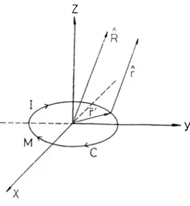
The idea of equivalent current concept consisis of deiermining the equiv alent electric and magnetic type currents [lowing along the. edge* of a wedge which produce the actual diffracted field ol the wedge when radiate in the a b sence of the wedge. Then, the edge diffracted li(dd for an arbitrary scatterer can be found b}^ the following radiation integral.(See Eigure 3.1)
j k Z
j
[ k x R x l + YR X (3.1)
47
t R jcwhere I and M are the equivalent electric and magnetic t\q;e currents in the place of the diffracting edge of the scatterer. Z and Y are the impedance and admittance of Iree space. C , as in Figure 3.1, represents the contour along the edge of the scatterer. R is the unit vector in the direciion of observation.
Away from the caustic regions, the above integral is evaluated using station ary phase arguments. The stationary phase points are the dilfraction points and the value of the expression in(3.1) should give the diffracted fields as cal culated by the CTD.
By comparing the stationary value of the integral with the Gd'D fields, one 10
CUAPl'ER :l EQi'lVALEM' C'lAiUEAT METHOD 1 I
Figure 3.1: Radialion of Eiquivalent Currents obtains tlie equivalent currents as
fc sin Pot (3.V)
M = - Z \ l ~ t (3.3)
k ^smpo
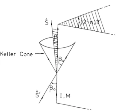
where and //¡C„ are the incident electric and magnetic fields tangential to the edge at the diffraction point and i is the unit vector along the edge. Ds and Dh are the .soft and hard diffraction coefficients. 00 is the oblicpie incident angle as showm in Figure 3.2.
Since these equivalent currents are derived from the GTD fields, they are only valid on the Keller Cone(/? = 0^). As a consequence of this restric tion, equivalent currents cannot be used for arbitrary direction of observation. Therefore to extend applicability of equivalent currents to include the direc tions which are not on the Keller Cone, an arbitrary diffraction angle 0 is needed as well as the incident angle 0„ in the expressions of the equivalent currents. (See Figure 3.2)
For this purpo.se, Knott and Senior[-l], on the basis of reciprocity consider ations, proposed the following replacement
CHAPrER 3. EQUIVALENT CURRENT METHOD 12
Keller Cone
Figure 3.2: Diffraction by an infinite wedge
and accordingly, they modified the equivalent edge currents as follows:
-V M = - Z . /8 k v'sin Q sin k \/sin ,0 sin Ds-Elani (3.5) ■■D^hU (3.6)
Although these expressions are consistent with the reciprocity principle, their derivation is not based on mathematical grounds.
To obtain the equivalent edge currents for arbitrary direction of observation, a new approach is suggested by Michaeli[5]. He proposed that the equivalent current expressions can be derived from the asymptotic integration of surface currents. This new asymptotic method is explained in the next section.
CHAPTER 3. EQUIVALENT CURRENT METHOD 13
3.2
Equivalent E dge C urrents For A rbitrary A sp e c ts
o f O bservation
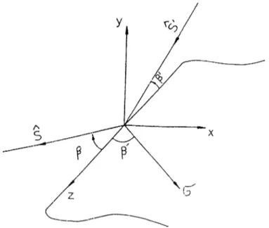
Consider a perfectly conducting flat surface' S on ihc xy-])lane with an edge (J as shown in Figure 3.3. At arw point on the <.'dge, the unit ve'ctor / is tangent to the edge, n is normal to the surface, and I lie binorrnal unit vector is gi\'en bv
b = h X I (3.7)
'The angles (j). (p . /i and ¡3 are measured as shown in Figures 3.3 and .3.-1. R is the distance to the observation point measured from the origin at the coordinate system, s and .s ¿ire the unit \-ectors for incident and observation directions. The far scattered field from tliis structure is given with the following radiation integral.
~, jkZ e-Efi ,
E = '--- r --- ä X S X
-l/T R J Js
where Z is the inti’insic impedance, k is the wa\’enumber and .]'i[x.y) is the total induced current on the conducting surface . In addition. Ay. and A·,, are given by
A·., — A- s * ky = k .C y
(3.9)
If the field point is not on a caustic of reflected held, then in the limit k oo , the surface radiation integral can be reduced asymptotically to a sum ol field contributions from an interior stationary point on S and a. boundaiw contribution expressed b}' a line integral C. The former gives the reflected field and the latter should represent the edge diffracted field.
Then, the edge diffracted field in (t,b) coordinate system is given Ir}·
.-jkR
-s X S X Jr(A, dt (3.11)
47
T R JcJowhere ”o” denotes the asymptotic end-point contribution at b = 0. Let
CHAPTER 3. EQUIVALENT CURRENT METHOD 14
Figure 3.3: A Perfectly Conducting Fdat Surface
CHAPTER 3. EQUIVALENT CURRENT METHOD 15 /?(/) = / Then '¡hZ i E‘‘ = s X ,5 X / 4/1 h ./r (3.13)
The edge diifracted field can also bo e.xpre.ssed as due to the equivalent edge currents along the edge
i k 7 e~NK- f
--- / [s X .§ X il -I- YS X 47t h Jc
Equating the two integrands, we liave
Zs X .5 X K ~ ZIs X ,s X i -1- Ms X t (3.15) Dot multiplying both sides of the equations with s x I and .s x .5 x /,
1 = = ¡ iw 5 ‘· ■ I" " " ''■< are obtained. Finally, by using M = - 4 - ; / - ( '5 x y ^ ) sirr o (3.17)
s - t cos ¡3 A b sin [3 cos (j) + h sin ¡3 sin 6 expressions change to
I = Kt — Kb cot (3 cos 0 (3.19)
, ^ ^sill 6 M = —Z-.—-Af,
sinp (3.20)
16
Let a perfectly conducting half plane is illuminated by a plane wave as shown
CHAPTER 3. EQUP ALENT CURRENT METHOD
3.2.1
H alf P la n e
in Figure 3.4.
Figure 3.5: Perfectly conducting half plane
Ih e local edge unit vectors are given by h = y, l - x and i - z. <p\ p and i5' are the same as shown in Figures 3.3 and 3.4.
If the incident field is given
— ^Q' cos<p'+ysmy ьіпф - г с о з /З ')
H' = Ys X Ё' (3.22) Using UTD, the total magnetic field is given by
Ht = Йоо + Ht-TD
Then the total surface current density is found from
(3.23)
JT = h x [Нт{ф = 0) - Йт{ф = 2тг)] which can be decomposed as
where
}U1 VALENT CIJRRE NT METHOD 17
■h = + Jl-Y^·· -f ( + J{)z (3.25)
4 '^ =-- 2Vsin/3'e--''^"':os J ^ o
(3.26) J f " = - 2 Y cos <Y cos
+ 2Y sin sin o c o s M O f ^ — Jf^'z co s ;3., M (3.27) an (] -ik. J { =: - V'-l ^ jk x s m fj COSO \ / '2 h j' s in ij' (3.28) ^.'.7 '· / ^ . I · I ' ^ - I " r n Q /A ^.-.//.--cosp j / == 4V''— — c o s /5 COS </i> e ^7T
r
>.77r/-l + - 4 Y sin (f>' —J=^f c · ^ · * · * ^ 0· ^ J \ f ‘IkX· f^\i\ fl' ^y^'x >in 3'^ c - ^ ^ \lr c -‘>^\lr + 2V'f i --- -:—37 y' (-'OS <7!»/2t ^•a'TT sin ¡3 - j k x s ill ¡j - j k r C( »s . / + 2V■e->/^ kxTt sin (3- sinis the geometrical optics approximation to the current density and is the fringe or ”non-unitorm” component as named by lifinnscv. VVe will examine the radiation of each component separately.
3.2.2
Fringe C om p on en t o f E quivalent Edge C urrents
le Ini'lP’e r.oivm nni'inf nl t hp r‘mn\7s.^ lr»nf C lirrc ilts reCJllll'CS
CHAPTER Т EQEIVALEM Cl ¡{RENT METHOD 18
Fringe curreni J C x . z ) can not be represeiiloid near the e<Jge(x=0) in a simple arnp^itiide-phase form. However, away from the edge, GTD gives a phase as —kxx ■ a. This phase describes J' [x·, x) as a wave propogating in the a direction which is the direction of dilfracted rays at the intersection of Keller cone with the half plane. Thus if it is iissumed that the ray behaivonr of the fringe surface field is valid up to very close edge, then the integral in (3..31) becomes infinite, if the following condition holds
X = a - X (3.31)
In other words, the singularity condition is satified when the phase of J^{x,z) cancels the phase of the exponent in the integral. This singularity condition represents a cone around the x-axis as shown in Figure 3.6. With this argument, Michaeli[7] stated that these expected singularities can be reduced to a single direction by choosing a proper skew coordinate system. Therefore a and z coordinates are selected instead of the cartesian coordinates x and z with the following relations.
x = cr sin ,5' z = z + asm ,e'
(3.32) (3.33)
CHAPTER 3. EQUIVALENT CURRENT METHOD 19
Using tlie new coordinates, tlie integration Irecoines
K^{z) = sin 5 / J^{asmf3 .z + a ca>s 3
J3y substituting the K^[z) into the equations (3.19) and (3.'i the following fringe current components.
. this yields
= y ^ 4
+
H L 4
M' =
zn;„„,il
The variables d{^di and dl are defined by
// - sin f7 2 { \ / F {l^ \í3,o) - ¡3' COSÇ I2)
^ j k sin /3'G{f3'. ij, G . o) 3.37)
2 sill,S'{cot ¡3 cos (!) + cot ,6i' cos (p -t- cos Ç ¡2 , J j ^ ^ j ^ H { i 3 ' ,S. ç) )
where
d{
=
G
" j ksin i;3'sm<j>{\ - sin S' cos o ¡2 siii/3 G[(3'U3,(p ,(p)
F{S ■,Si4') = sin ,/?'(sin ¡3' — sin p cos <t>
— cos /61'(cos d — cos s') (3.40)
G{S ■,/S,
9
■, <!>) =
sin/3
'(sin/3
cos (^ + sin/S'cos 9 )+ cos
s'
{cosS
— coss')
(3.41)H { S ' = C O t / ? ' [ s i n / 5 c O S ? ! > + C O t / 5 ' ( c O S / 0 - C O S /3 ')]
CHAPTER 3. EQUIVALENT CURRENT METHOD 2Ü
TI103 resulting equivalent fringe current expressions are finite for all as]:)ects of illuniincition cuid observation except for the case .s — s' — a. In addition, there is an integrable singularity at s — cr direciion as ex]>ected.
3.3
D erivation o f PO E quivalent E dge C urrents For a
H a lf Plane
In the following end-point evaluation
The phase of -) —kxx ■ s . Hence, the singularity condition of the intesi'al becomes
X · s — X (3.41)
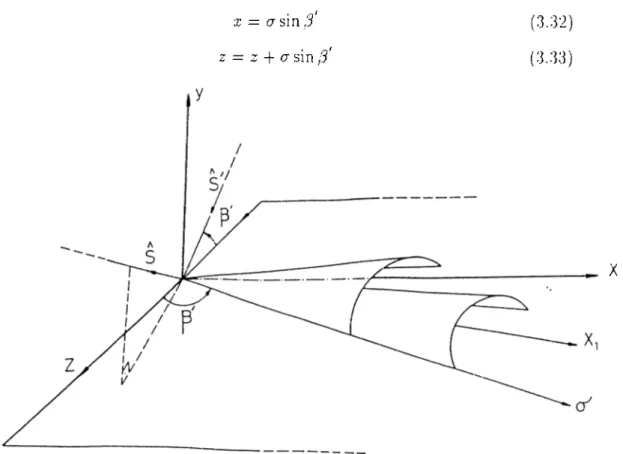
'I'he replacement of .f-directicjii by the a-direction for the integi'ation a.s in the case foi· fringe currents doe.s not have similar elTect on t he PO components. Because, such a step merely replaces the cone of singrdar ,s-directions. b\· a.n- other cone, defined by ii · d = ■§ · d" and only for grazing incidence, a — s . does the latter collapse into a single dinjction. s = a . However, tire abo\ e argument· assumes a skew coordinate direction fixed by the incidence angle for all olrser- vation directions, in fact, for equivalent currents there is no need for such a restriction, the skew coordinate direction may be determined by both the inci dent and observation directions (J and s). So, for each observation direction, the skew coordinate direction on the surface of the half frlane is detennined separately.
To apply this ap25roach, we will again use the (cr, z) skew coordinate system as shown in Figure 3.7 with an arbitrary skewness angle 9 as follows
X — a sin 0 z := z + a cos 0
(3.4.5)
CHAPTER 3. EQUIVALENT CURRE^'T METHOD 21
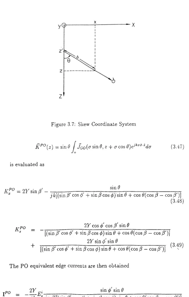
Figure 3.7; Skew Coordinate System
K^^{z) — sin 0 / Jao{<^ sin 0,z A cr cos
J o
is evaluated as
(3.47)
= 2 rsin /3 ' sin 0
jibi(sin 0' cos 0' + sin 0 cos <^) sin 0 + cos t^(cos 0 — cos 0')] (3,48)
K f ° = - 2Y cos f cos 0' sin 6
+
[(sin 0' COS (?' + sin 0 cos 0) sin 6 + cos i?(cos 0 — cos 0')\
2Y sin 0> sin 9
[(sin 0' cos 0' + sin 0 cos 0) sin 9 + cos 9{cos 0 — cos 0')] The PO equivalent edge currents are then obtained
7TT
(3.49)
9Y .
1^0 = sin (p’ sin 9
j k ^sin /3'[(sin/?' cos 0' + sin 0 cos 0) sin 9 + cos ^(cos 0 — cos 0')] . Q________ cot 0' cos 0' -1- cot 0 cos 0___________ j k [(sin 0' cos 0' + sin 0 cos 0) sin 9 + cos ^(cos 0 — cos 0^^
CHAPTER 3. EQUIVALENT CURRENT METHOI) 22
2 7. sin·çişin 0
jk ~ sin/?[(sin f3' cos (/;' + sin /5 cos (¡>) sin 0 f cx>s i^(cos ,3 — cos/3')J
(3.51)
It is seeij that, these expressions are the function of ilie skewness angle 0. Hence the\^ are noniinique.
Let
I = c + 1}^o (3.32)
M = NC + (3.53)
'I'o lincl tlie radiation iVoiu the equi\^alent line curnnits I and M, vve need to the e.xpressioiis for the equivalent currents at 3 — 3 dire(:tion(.See Ap]>endi.x A). For that reason, it is observed that
77) (3..51)
M^{3 = 3') + = /3') = Mr;TO (3.5.5) Tins means that, the radiated electric field from the fringe and PO equiva lent currents is independent from the a.rbitrar3' skewness angle 0 and it exacth- 3'ields the GTD field.
On the other hand, the selection of 0 represents the singularity map of the PO equivalent currents. At ¡3 = /3\ the PO equivalent currents reduce to the following ones.
_ + l,/ .Î Ç İ 4 (3.56)
j k ~ sin^ 3 (cos ^ -h cos 0 ) j k ' sin Ş
M^^{3 = 3') = sin j)
CHAPTER 3. EQUIVALENT CURRENT METHOD 23
3’hcse expi’esi;ions are only singuliri' at the incident and reilccted transition regions. But the PC) equivalent current.s may have additional singularities depending on the selection oi 0.
Accordingly, depending on both the incident and the (jbservation diiections if we choose the skewness angle 0 as follows
cot 9 = — cos [3 — cos ¡3'
sin ¡3' cos (p' + sin ¡3 cos (jj (3.0S) 'Phen PC) equivalent cui'rents become
rP O
= jh ' sin ¡3'[(cos [3 — cos (3')- ~\- (sin (3 cos A + sin ¡3' cos ©' )'·^]sin (p'(sin ¡3 cos 0 + sin ;3' cos o ) sin ©(sin ¡3 cos (¡) -f sin i3' cos g )
j k ' [(cos ¡3 — cos f3'y + (sin 3 cos 6 + sin ¡3' cos g )-\
-b — //! (3.59)
sin ©(sin ¡3 cos 6 + sin l3' cos g )
j k """ [(cos/Cf — cos f3'y + {sm/3 cos 6 + sin ¡3' cos g')-] (3.60) It is noted that the equivalent current e.xpressions gi\-en in (3.59) and (3.60) are the same as the ones in [6] where they are determined for a finite size phate by an a]rplication of Stokes’ theorem.
When the singularities are e.xarnined, the following conditions are obtained.
and
( b p s — -K
P - 0 '
[3.61
(3.62) This represents the incident and reflected shadow boundaries on the Keller Cone and we see that, the singular directions are not expanded by this selectioji of 9.
Physiccilly, the direction of skew coordinate a in this case is the direction of the projection of (i — 5 ) vector onto the half-plane. It is a function of both s and s , as described earlier. The natural question to ask at this point is what happens when (s — s ) vector has zero projection on the half-plane; in other
CHAPTER 3. EQUIVALENT CURRENT METHOD 24
words, wlien (s — s ) licis only iiornial coinpoiient to the half plane surface. In this case, the above deiinition of a fails. However, a close examination reveals that when (s — .s ) vector has only uormal component to the half-plane, the observation dii'ection is either on the incident boundary (s = s ) or on the shadow boundary of the Keller (.'one. Both of these cases correspond to directions for which the field is non ray-optical and the equivalent current concept is not valid.
3-4
H igher O rder Equivalent C urrents
When a perfectly conducting flat plate is illuminated by a plane wa\'(\ the fringe cind PO equivalent currents due to tli(· first order diffraction will be excited on the edges. The radiation from these curixnits yields the single edge diffracted fields. But to obtain more accuraie results, it iruiy be iieccesary to include the multiple diffractions between the (xlgcvs. 1 liei'efore, equivalent current method can be modified to include tfie higher order interactions. Accordingly, the fields of the multiple diffracted I'ays l)ettveeii the plate edges are comi)uted b}^ constructing the corresponding eciuivalent edge currents ¿md using them to compute the far scattered field, rihs [n'oeedure provide us to obtain the contribution of the higher order dilfraclioiis to llie total far scxittered field.
Consider a perfectly conducting flat ¡date which is illuminated by a plane wave as in Figure 3.7.
It is known that the diffracted (iidds from a point on the edge is given by UTI3 as follows ' 4 ¡'.h o
.
^7.
o l \T V
^-j7r/4 Z3s = - - 7 = — h v ‘27
r^-smpF[kLa{(p - (p')] ^ F[A;Ca(^ + ?i')]
Q — 0
COS COS O-Fd)
where
CHAPTER 3. EQUIVALENT CURRENT METHOD ■N
aud
Figure 3.8; Edge interactions in a flat plate
L = p s m \ 3 (3.66) with the {T,<r>) coordinate systenn which is defined at the diilraction point.
On the other hand, it is assumed that the diffracted field from the second edge is almost a plane wave when it illuminates the fifth edge. The diffracted rays from the edge 2 are incident to the <idge -5 with the following tangential fields.
E[^,Xat edgeo) = /5 · E^^
- O (3.67)
edgeb) = /5 · /7'·' (3.68) Then the equivalent edge currents at edge .5 due to double diffraction is given by
CHyiPTER 3. EQ VI \ '.4 LENT CURRENT METHOD 2G
= l}{TIUJai ,dgeo),;Cl^\<pJ) + l-poUnaniM. tdgeo),/3,/3', 9 ) (3.69)
edgeo),l3,3',dK6) T cdgco). ¡3, 3'. <?. o ) (3.70) The radicited el(v“ctric field from these equivalent currents.
E =
-jkR p
4ir [R X R x y| + Y l i X (3.71)
where R is the observation direction and k^: = kR-x, ky — kJi-y. In the notation of the higher order current.s in represomts the ordei· of the diifraction and q sliows the riurnljer of the edge (hat equivalent currents exist.
In the anal3’sis of higher order dilfractions one has to consider the shadow ing effect of the surface dilfracted rays. Since this causes to the illumination regions. In the radiation integrah a and b rejiresent the limits of th.c illu mination region on edge O- It is dependent to the incident wave' din'clion. ]>ola.rization and the geometry of the plate. If tlie similar integral is i-'peated for each straight part of the edge by defining the a]>propriate integration limits on the opposite side of the plate. Then the sum of the integration contributions will be equivalent to the second order diffraction.
Chapter 4
BACK SCATTERING FROM FLAT
4PLATES
In iJiis chapter, (o exaniiiic tlie accura.cy of the fringe and PO eciiiivalenl edge currents, we applied them to the problem of backscatteiing from the perfectIv conducting rectangular and triangular plates.
Eventfiough there i.s no analytical solution to these plate problems, tlie calculations of the Irackscattered field has been investigated by sorm? antliors using high frec|uency techniques.
For the square plate problem, Ross[]0] has ap])lied the GTD and PO meth ods to predict the monostatic RCS. Ross also obtained a wide range of measured data[lO] and his results were in agreement with the measurenieiits except for the regions near edge-on incidence. Later, more accurate results are obtaiiu'd by Sitka[9] who employed GTD based equivalent currents and included the higher order ecjuivalent currents into the analysis. The results for the backscattering from the triangular plate are also obtained in [9].
In the present analysis, we applied the fringe and PO components of I lie ecjuivalent edge currents to the same backscatteriiig problems from the square and triangular plates. In addition, the currents are combined with UTD to include the contributions of the higher order diffractions as explained in section 3.5. The analysis is also performed for E and H polarization cases separately. For each case, the results are compared with the previous anabasis of Sitka and measured data.
It is known that the fringe and PO equivalent edge currents have the in finities in the incident and reflection shadow boundaries on the Keller Cone.
CHAPTER 4. BACK SCATTERING FROM ELAT PI.ATES 28
Therefore, tlie biickscaUering results from the flat platc's at the broadside di rections become singular. On the other hand, U'i'D plane wave diffraction coefficients are used to consider the edge interactions. But in the (rausilion regions, the diffracted fields from the edges are not ray optical.
Th<i total eciuivalent currents are given by
I = YEUMo\<P,l3\3) + (-1.1)
M = Z /T D h (0 \ç S ,//,T ) vvliere
Os,h,2i^\ 9, ¡^' 9 - J ' (^1-3)
where and e.x'pressions are due to the iVinge and PO ¡tarts of tlie equi\alent curi'ent components. It is assum<.“d that the e(|ui\'alent currents exist on the edges in the direction of the edge's tajigent vector.
Two types of polarization for the incident plane wave is examined sepa- ratel}'. E-plane polarization occurs when the directicui of tlu' incident electric field is in the observation plane. If the observation jtlanc' is the xz-plane. then iJie ITpctlarized plane wa.ve becomes;
r ’ i (T. bill 0 co s (j)+ r cos (/)
L· — (i‘0 (4.4)
IP = YR X E‘
Sirnilarl}·', H-plane polarization occurs when the direction of the incident II field is in the observation plane.
Il-polarized plane wave;
ğ i _ ^ j k [ x sill 0 co s (p + z co s 0) ^ ^
IP = Y R X E ‘
(4.6) (4.7)
4.1
Square P la te
Let a. perfectly conducting square plate is illuminated by a plane wave with the propagating vector 5,· as showui in Figure 4.1. It is seen that xz-plane is
CHAPTER 4. BACK SCATTERIKG FROM FLAT PLATES 29
Figure 4.1; Perfectly Conducting Square Plate
the observation plane and the first order equivalent currents are excited on the edges of the square plate. The length of the plate is shown by ”a’b
Then the single diffracted fields from each of the edges of the square plate are evaluated by using the total equivalent edge currents as follows
From edge 1: (4.8) , - j k r where (4.9) and /3 = 0' = t/2 </> = (/)= 7t/2 — 9 (4.10) (4.11) From edge 2: pi _ ^62 — - A [cos0(D,(4’','t>,l)'j)El, + 47T - j k r (4.12)
CHAPTER 4. BACK SCATTERIKC FROM FLAT PLATES 30 47T -jKr where and
/3 == r/2 +
0 (4 ~ -K ¡2 — 0 o — S — /2 From edge 3; j k r~ jk -r ril - A r i ) U l „ \ a A A where and (j =-_ ji' = Tr/'i (j) — S =. 7t/2+
(4.20) From edge 4: E'„ = A \cos0(D,(4;,^J\?)E\„^D,(,p\<!,Ji\l))HlJW(0,a) 47T ^-jkr j k r . ~ j k r T = (4.22) where /4' = -kI'I - 0 ^ = 7r/2 + 6/ (4.23) (4.24)CHAPTER 4. BACK SCATTERING FROM ELAT PLA'TES 31 arul vviUi Ф' = ф-= - /2 W{0,a) = I Jo jka.ino FmikasmO) ' ' kaCmO (4.26)
In the r('preseiilati(ni , in re])rescuts the edge nuinlxM·, n shows the electric field (.•(nnpoiient and q is the single edge diilVacticni. d'hen the total siiiLde diffracted field becomes
whei*e 0 component: ^ E]ao + E]^a El = E l + E l + E l + E l (4.27) (4.28) О component: -^4 ~ “*■ ^'ч-i + (4.29)
T'lie liiglun· Older diilVaction rnedianisnis are anal\'.si/ed for 14 and H plane Ccuse.s in the ne.xt .sections.
4.1.1
E -P olarization
When tlie higher order intercictions between the edges of tlie square plate are considered according to UTD, then it is observed that the edges 2 and 4 don’t cause diffracted rays on the surface. However, the opposite edges 1 and 3 interact correspondingly. Therefore, due to the double diffraction, the following second order edge currents exist on edge 3.
= Щ М Ф ' = 0, = тг/2 + ^ = ¡3' = ТГ/2)
CHAPTER ■/. BACK SCATTERIKG FROM FLAT PLATES 32
where
- ^/2 - 0^<P - 0.13 = n/2.a) ■j/:a
(4.32) where Dl^ is tlie UTD hard diil'raction coeilicient on edge J and t he factor 1/2 is due to grazing incidence. Tlie s('Cond order currents ,/j- and 3 // on edge J can be found .similarly. Then the total st'cond order diffracted field is gix’en by the following integral.
E'^ —— ( / \R X R X J'f + Y R X
Itt h Jo '
^ [It X f i x f j + YR X (4.33) lo
The third order diffractions are als<; computed by using the similar ap proach.
4 .1 .2
H -p olarization
In lI-])olarization ca.se, onh' the edges 2 and 1 cause difIVacted rays on the sur face. In the analysis of the higher ordei' diflVaction mechanisms, it is obser\'ed that the diffracted rays from the edg(; 2 illuminate the whole of the edge I and a part of the edge 4 for 0 < 7t/ 4. On the ol.her hand, for 0 > Tr/4 only edge 1 is partially illuminated by the diffracted rays frcnn the edge 2 as shown in Figure 4.2.
Then the second order ecjuivalent currents on the edges 1 and 4, due to the double diffraction, are given by
On Edge 1:
l i = ^^an02{(l>' = 0,(p = 7t/ 2 - 9 ,0 = V - 0,,3 ~ 7t/ 2 )
M l = = 0 , <;6 = 7t/ 2 -- 0, /4' 7T - 0, /3 = 7t/ 2 )
CHAPTER 4. BACK SCATTERiKG FROM FLAT PLATES 33
•y
Figure 4.2: Edge Interactions in the Square Plate
Hian = edge2)s\ndDl{<?' =-- 7t/ 2, d = 0 J = tt/2 + 0,s) ^ with cos 6 On Edge 4: = 0,c> = ^/2, /3' = 7t/2 - e j = It/2 + 6) (4.38) M l = ZHl^Di,{<f>' = 0 , 9 = z/2,j3' = 7t/ 2 - 0 J = it ¡2 + 6) (4.39) where
= \ cdge2)cosODl{9 = it¡2,9 = 0,j3 = it¡2 + 0,3) (4.40) with
s =
cos 0
C HA PrE R 4. BACK SCATTERING EROM ELAT PLATES 31
'J'hezi the coiitrilzutioii of the second edge to tlu‘ total second order diil'rac tion is given by , 'y I'yinojc where £.2 = / [/¿ X f i X f 2 + Y f i X •'Itt Ji J o /'4’nm X + / [Rx H x I¡ + Y R X Jo (1.42) U m a x ~ a 0 < tt/ J a cotí? 6 > 7t/4 (1.13) and J m a x — i(l — tan Í?) 0 < Tr/4 O 0 > 7t/4
The contribution of tlie edge 4 to the second order diiiVaction i.s coinpnled in a similar way. Then the total second order diilVacted field is evaluati.'d as
E^ = E^ + E^ (4.43)
4.2
T riangular P la te
The perfectly conducting triangular plate , as shown in Figure 4.3, is illumi nated by a plane wave which is lie in the xz-plane. The xz-plane i.s again the observation plane.
The single diffracted fields from the edges of the triangular plate are ob tained as follows
From edge 1:
CHAPTER 4. и л е к SCATTERING PROM ELAT PLATES
Figure 4.3: Perf(x;i,]y Conducting Tricmgular Plate where ф = ф = 0 fj ^ ß ‘ =. тг/2 (4.4S) (4.49) From edge 2: E], = ^-^[{Ехпа120ъ(ф ..φ,ß\ß) + c o s a | 2 A n β D 2 { φ \ φ J \ ß ) ) H l 47Г
+ cos a/2 sin Ф, ß ', ß)E\^,]M{в, a)
tan (4.50) j k EI2 = ^'/2 sin 9Е1^{ф\ Ф, ß', ß) + sin q'/2Z)2(<^', ф., ß \ + sin a!2Ds{ß\ Ф, ß \ ß ) E i J M { e , a) (4.51) where ß = cos ’(—cosa/2cos ¿1)
CHAPTER 4. BACK SCATTERING FROM FLA'I^ PLATES 3()
iK = S —■ cos * (cos a /2 cos Ö) (.1.53)
(P =z (■) = COS-1 I — sina'/2 cos (7
y /1 — cos- 0 cos'- Cl /2 ' (4.54) 'Voni edge 3:
[A.j^ ~ — [ ( -CO.S a /2 sin 6'./j'v(c/, d , /.7 . /7) + siii o/2/7ij(c'/. d , /7’, /3))//),^„
4
— cos a/2 sin 0Da{& ■<?,S N^)K[ai]^l{C_a) (4.55)
—
~
[(sin a/2D-2{(,’>■
, <C S\,3)
+
coso/2sin
0J\lo, o, 3', 3)141,
4 A
+ sin c\/2I)^irp, d: 3 ) K l r ] M (0. a) where
and
fi' — cos ’ (co.s a /2 cos 0)
0 — cos ‘ (—COSO¡2 cos 0)
(4.57)
(4.58) d, <? same as the second edge.
In addition, /■26 ^(6) = / dy = 2b Jo (4.59) M(0, a) = /
— as\Yi{k cos 6a) k cos Oa
^ j I: cos Oa (4.60)
The total single diffracted field becomes
CHAPTER 1. BACK SCATTERING FROM FL A T PLATES O I where 0 component; (p coni])oncnl; Eo —' -t- N(>2 + E'os {■'UT El = El, + E l, + £■’„
The higlK;r older dilfraction medicanisms are aiialysized for I] and H polar ization cases separately in the next sections.
4.2.1
E -P olarization
In thi.s ])olarization, it is seen that all edges cause diffracted ixiys on t he sur face and the liiglier order diffraction mechanisms can he mainly sjilit into tlu' following two parts.
i) The dijfracted rays caused b\· tlie first edge of tlie triangular plate il luminate tlie second and third edges. Thr-n the corre.si.)onding second order ecp.iivalent edge currents on the edges 2 and -3 are gix’on hy
On edge 2: I 2 = = 0 , 0 , 8 ' = a/2 .;?j M;^ = Z H l M o = 0 , 8 , 8 ' = 0 / 2, ,h) vvdiere H l n = e¿í7e l) s in a / 2i;¿(V/ ---- 0,8 = 0,,8 = t: / 2 ,z) ^ On edge 3: í^, = irtunD2Í8'=--0,8,8'= ^ - 0/2,,8) U l = Z H l^ D ^ [ 8 ' = 0 , 8 ,1 8 '= 7r- a/2,f8) (4.68)
CHAPTER. 4. BACK SCATTER INC IHiOM FLAT PLATES 38
where
H L = ed gel )s\na/2Dl(o ... 0,o - 0 , 8 = Tr/2,c) , - j k .
(p is determined by eciuation (-1.5 J) fur each edge and 3 is evaluated by equaticjiis (4.53) and (4.58) lor second and third edges respective!}'.
Then the radiation of these equivalent currents is given by
ULt = --- — [ [h -K fi x 4Tr li Jq
+
f
[R X R. X /j -i- Y R X /l7|]eJo (4.70)
ii) On tlic otJier hand, we sec tliat iUc diffracted raws fi*oin the edge 3 illuminate the edges 1 and 2 dei.Kuidiiig on 3^ as shown in Figure 4.4.
The second order equivalent edge curi*eiits on I lie edges 1 and 2 due to the diifrcicted rays from edge 3 are given as follows
On Edge 1: I? = = 0 ,6 = 0,n‘ = ,r/-2 - 1% + a/2.;J = it/2) (2.71) MJ =
Zlfi
J U p = 0 , 6 = 0, 3‘ =w/2
- fi, +0/2,0
= -/2) (4.72) where H L = - W M««(A -
< ^ n ) O i ( 6 , 6= 0, /?, n W
(4.»)
^ Va On Edge 2; li = H L Di(6' = 0 , 6 , 0 = - ^ - Po 6 a,/J)CHAPTER T BACK SCATTERJ.XC EROM FLAT RLA'EES T)
Figure 4.4; Edge interactions in the tria.ngnlar plate
Mo = ZHl^^D\y((p = 0 , Ó, d' =z IT - Bo + o, ;4) where HE V'^ and edge3)sin{6o - a)Di^{ó = 0 , 3 ^ , s ) — =:r
H\{ai tdgei) VeJ----cosi
(4.7.3)
(4.76)
(4.77) B and 6 for second edge are given in terms of 0 with the equations (4.5-3) and (4.54).
In addition, s and z are the integration parameters which have the following relationships.
For Edge 1:
cos{Bo — tv/2) tan q/2 + sin(/i^, — o/2)
2 = s{y) cos(/i,, - a/2) (4.79)
CHAPTER 4. BACK SCATTERIXC FROM FLAT PLATES 40
7 = 7t/ 2 + a/2 - IL,
— 2 tail ( a / 2)
cos 7 -f t ail a/ 2 sin 7
/cos 7 — tan a /2 sin 7 ) + 2« tan o /2 sin 7·
cos 7 -1- tan a /2 .sin 7 (4.82)
These integration \'arilrles as .shown in' Figure 4.4 are snhstii uteO into the following radiation inti'gral with the defined equivalent run cuts.
rym u ■Itt R -( / [k X R X 1/ + Y R X [ii X R x l l A Y R X '-'"^^/.v') .84j where y 11:'l.v j a [ t a 11 Q / 2 + t a n (R, a / 2)] ¡ij < a a !l > (X (1.84) and a do < 0 7t/2 + a /2 > ,3o > ---- 2a¿.rna/2.uг^ ^ cos^l — t a n a / 2 s i n R ‘ ^ ' a (4.85)
This procedure i.s repeated for the diffracted rays from edge 2. Then the following sum of all integral contributions gives the total second order dilfracted field.
CHAPTER 4. BACK SCATTERING FROM FLVT PLATES
4 .2 .2
H -P olarization
In conirasl to tlio Ivpolarizaliori case, in 11-polarization tlie first edge dovisirt Ccuise to tlie sui'ia.ce diili'actiori. Ilo\ve\aM\ second and third edges c'reatc the diffracted laiys and the corresponding ecjnivaknit ciirrcnts on the o])])Osiia‘ ('dges. Therefore, tlie second diffraction can be coriiputed hy using th(' sec^nul inecli- anisiTi mentioned in tlie j^revious section.
Chapter 5
COMPARISON OF THE RESULTS
Here, the results of tlio pj'csent analysis of the stjuaix? and Iriangular |daics will be presented and coin])ared with tlie previous results of Sitka[9j, Koss[IO] and the measured data,[9].
In both flat plates, for eacdi polarization case, the total far scattered field is obtained the summation of all integral contributions including computed liiglier order diffractions, riic integrals are e\aluated numerically using pulse functions with 0.01 wavelength steps, 'riien the total far scattered held is found as
(0.1)
In the analysis, e.xccpt the E-polarization for square' plate, onl\' the first and second order diffi'actions are used. Tlie scattered field is obser\ed in the Irackscattered direction and rnonostatic RCS is obtained as a function of 0.
In the hackscattering from the scpiare jrlate, E-plane pattein results ai(.' shown in Eigure o.l. The first, second and third order diffractions are used in the analysis. It is observed that there is no difference between our result and Sitka’s solution and both of them are close to the exjrerimental data for 0 < 80.
In II polarization illumination for the square plate problem, the agreement between our result and the result in [9] is good and they coincide with the experimental result away from the grazing incidence region (See Eigure 5.2). Furthermore, we were able to predict the small oscillations near edge-on region by including the second order currents into the analysis.
In the determination of the backscattering from the triangular plate, for 42
CHAPTER o. COMPARISON OF THE RESUIHS 13
E-polarizatioii case, only the first and second order diffractions are used in tlie cinalysis. However, in [9], Sitka Inis used tlie first, second and third order dilfiau - lions including the ¿ill edge interactions. On the other hcind, in H-poIarizalion case, although the first ¿ind third order diifrcvctions. corner diffrciction and edge wave inecluuiisin are included to tlie ¿uialysis, second order diffractions aie omitted by claiming that the doulile diffrcicted rays between the edgds 1 anil 2 of the triangle ¿ire cancelled by the diffiaicled J'¿ıys lietvveen edges 2 and 3 in [9]. This Ccincellation does not occur for the new fringe and PO ecjui\7ii(Uit currents. Therefore, we used the first ¿incl second order diífг¿ıctions for that pohirization.
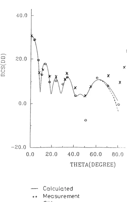
13-polarization results for the different siz(xl tiTingrihir pbites are siiown in Figures 5.3-5.6. It is obser\ed IVoni the figures that the present soluiioijs ai'c closer than the ones in [9] to the measured data for 0 < 20. In ¿idditiou, in Figure 5.5, Sitka pj*edicts a nonzero sc¿ıtleı‘ed field at 0 ~ ISO. Howe\'ia‘. in this ¿inalysis a zero field is obtained as expected.
The H-plane calculations for the triangular ]d¿ites are shown in Figures 5.7 and 5.8. Both present and Sitka’s results are fairly accurate ¿iround tiie broadside direction (45 < 0 < 120), ¿md our results Imve a slight 1\' l>etter prediction of the vari¿ition of Huí pattern for () > 90. Bot h results deviate from the experiments for 0 < 45.
CHAPTER .5. COMPARISON OF THE RESULTS a = 3.125 I am da ÏHKTA(IN DEG) — Calculated 0» Measurement ----Sitka XX R oss
CHAPTER 5. COMPARISON OF THE RESULTS 45
— Calculated »« Measurement ----Sitka
XX Ross
CHAPTER 5. r OMPARl SOC OP TUP RPSUITS IG
,10.0 r
a =
41
amda alfa =60
deg----sitka
— calcuiated — rneosured
ΤΗΕΤΛ(ΙΝ DEG)
CHAPTER 5. COMPARISON OF THE RESIHHS 47 10.0 a - 4. i yn (1 a a 1 f a -·· --i rKi'■/.{
S
CO o o "7^ 1—( G V I o G 0 ,( — 1 u . u - 20.0 M ' 'ir^ / - 3 0 .0 -4-0.0i / /
'' I
1'^· !'\ "ill i l · If /i[[.:.
•4.3.0 ( y.V \\ 7 1\
V \ \ /^, ' I 1 I \ 1 I 1\ ' I i\
a;
00.0 135.0 .00.0 TKETA(IN DEG) ! i. A ‘.. cciicii.^ated •meOsSuradCH AP TER 0. COMPARISON OF THE RESULTS 48 ■ '1!. a I; d a 1 i a -·" 9 0 d c; ij cq Q m o Pi 10.0 0.0 pq lO CO 9 1 0 . 0 1 -o -2 0 . 0 -- 3 0 . 0 - 4 0 . 0 --- sitk a — calcukitev·;' — rneosLireci 1 8 0 . 0
CUAFTER 5. COMPARISON OF THE RESULTS •H)
THETA(IN DB)
----sitko
— calcu'ialed — meosured
CH AFTER 5. COMPARISON OF THE RESIJL'IS 50
o. = 4 Ia m d ;; aÀ fa-lG do'in'oc 0.0
Λ
İÜ .0 i--40.0 \ 1 pi 1." .. ; 57' ! ^ 4 â ■ V i-! \ 1. \/ /
pN. \ 0-1 i - \ \ ГА-1 \ ' -M\c\ n _. 1 \ •f Λ ^ 0 \ l \ r \ r' ' I 1 11 / , i ! ■ J\
\VѴ'Ѵя
0.0 45.0 ·■ ·· sitka — calcuiated — measured 90.0 135.0 THETA(IN DEG) 100.0CHAPTER. 5. COMPARISON OF 'HIE RESUL'TS 5.1 a = 9 1 a m d a a l f a = 3 0 d e g r e e
----Sitka
--- calculated----measured
THETA(IN DEG)
Chapter 6
CONCLUSIONS
In tlie present study, we derived the FO componeiits of the ecpiivalent edge currents for a lialf plane similiar to the Midiaeli's a]jproacli for l lie elirniiiation of the infinities of tlie fringe current co)nj)onent. By using; a different selection of the skew coordinate over the half |dam>, we obtained tlie 1^0 ecjuivalent current expi’essions. It is seen tl)at líense e.xpi-essions are tlic' same with the ones obtaijied in [6].
Furtliermore, by obtaining the PO etpiivalent currents de|)ending on an arbitrary skewness angle, it is shown that tlui radiation fi'oin the fringe and these arbitrary PO equivalent currents ai(' unique and yields the G'PD held, d herefore, tins proves the expectations that tlie n(;nuni(|ue c(|uivalent currents must give the unique radiation.
Later, the fringe and PO ecpiivalent currents, that is more general than the OTD based ones, are applied to the prol:>lems of the l^ackscattering from tlie perfectly conducting square and triangular plates, d'he higher order diffractions a,]'e considered in the analysis in order to evahuite the interactions between the edges of the plates by using the IJd'D. Tlnm, in the comparison of tlie present results with the previous results of .Sitka some improvements are obtained.
A p p e n d ix A
R a d ia tio n F rom T h e I n fin ite L in e S o u rc es
Let an infinite line source, carrying electric and magnetic type currents I and M.
The radiated electric field from the line soui'ces is given by
E =
47r (.; X i X Hz ) + Ki X AHz )] - - ) -z p ’. .rfx (A.l)
where z and p are the observation point coordinates as shown in tlie iollowing Figure.
Z
I
Figure A.l: Infinite line sources If equivalent currents are in the form
APPENDI X A. RADIATION FROM THE IN FINITE LINE SOURCES
5-1
i( .') = (A.2)
(Λ.3)
Tljen inte^ra.1 l.)econies
Γ[3
X .5 X / ( , : · ') + r . i X :\7(r'l]^ ^ - j h N c o s E + y / ( z - z ' ) ^ + P )
ν Ί ' - - ' Ρ + ρ ' '
ifc (Λ.4)
Tills integTciI can lie evaluated by tlic incihod of stationary phase. Assuming th a t I(z' ) tuid i\i{z ) are slowly varying and k is large.
Tlien the phase of the inti^grand
- -[-^'cos V + + e ] (A.5)
Solving 'E'{z[] O, tlie slationaiy i)oiiit is Ibuiifl as S = Tliat is
cos β —
\ / ( , r - ^ ') - +
p-Racliated field
E = j k Z [ s x s K l ( i 5 = i Z ) N Y s x M { e = (A.7)
At high frequencies, the rcidiation from the line sources, as derived liere, yield the field in the direction of the diffracted cones(i.e Keller -- /3' ).