FIBER OPTICAL NETWORK DESIGN PROBLEMS:
CASE FOR TURKEY
A THESIS
SUBMITTED TO THE DEPARTMENT OF INDUSTRIAL ENGINEERING AND THE GRADUATE SCHOOL OF ENGINEERING AND SCIENCE
OF BILKENT UNIVERSITY
IN PARTIAL FULFILLMENT OF THE REQUIREMENTS FOR THE DEGREE OF
MASTER OF SCIENCE
by
Başak Yazar
ii
I certify that I have read this thesis and that in my opinion it is full adequate, in scope and in quality, as a dissertation for the degree of Master of Science.
___________________________________ Assoc. Prof. Bahar Y. Kara (Advisor)
I certify that I have read this thesis and that in my opinion it is full adequate, in scope and in quality, as a dissertation for the degree of Master of Science.
___________________________________ Assoc. Prof. Oya Ekin Karaşan (Co – Advisor)
I certify that I have read this thesis and that in my opinion it is full adequate, in scope and in quality, as a dissertation for the degree of Master of Science.
______________________________________ Assoc. Prof. Hande Yaman
I certify that I have read this thesis and that in my opinion it is full adequate, in scope and in quality, as a dissertation for the degree of Master of Science.
______________________________________ Asst. Prof. Ayşegül Altın Kayhan Approved for the Graduate School of Engineering and Science
____________________________________ Prof. Dr. Levent Onural
iii
ABSTRACT
FIBER OPTICAL NETWORK DESIGN PROBLEMS: CASE FOR TURKEY Başak Yazar
M.S. in Industrial Engineering Supervisor: Assoc. Prof. Bahar Y. Kara Co-Supervisor: Assoc. Prof. Oya Ekin Karaşan
July 2013
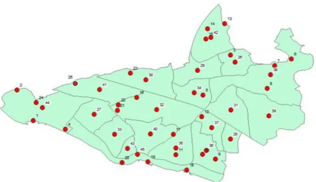
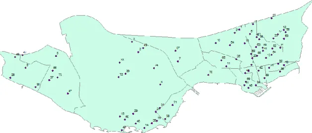
The problems within scope of this thesis are based on an application arising from one of the largest Internet service providers operating in Turkey. There are mainly two different problems: the green field design and copper field re-design. In the green field design problem, the aim is to design a least cost fiber optical network from scratch that will provide high bandwidth Internet access from a given central station to a set of aggregated demand nodes. Such an access can be provided either directly by installing fibers or indirectly by utilizing passive splitters. Insertion loss, bandwidth level and distance limitations should simultaneously be considered in order to provide a least cost design to enable the required service level. On the other hand, in the re-design of the copper field application, the aim is to improve the current service level by augmenting the network through fiber optical wires. Copper rings in the existing infrastructure are augmented with cabinets and direct fiber links from cabinets to demand nodes provide the required coverage to distant nodes. Mathematical models are constructed for both problem specifications. Extensive computational results based on real data from Kartal (45 points) and Bakırköy (74 points) districts in Istanbul show that the proposed models are viable exact solution methodologies for moderate dimensions.
iv
ÖZET
FİBER OPTİK AĞ TASARIMI PROBLEMİ: TÜRKİYE UYGULAMASI Başak Yazar
Endüstri Mühendisliği Yüksek Lisans Tez Yöneticisi: Doç Dr. Bahar Y. Kara Tez Eş - Yöneticisi: Doç. Dr. Oya Ekin Karaşan
Temmuz 2013
Gelişen teknoloji, fiber optik kablolar ile internet erişimini arttırmaktadır. Bu şekilde daha hızlı, güvenli ve geniş bantlı olarak sağlanmaktadır. Bu tezin konusu, Türkiye’nin en büyük servis sağlayıcısının gerçek bir probleminden ortaya çıkmıştır. Problem, şirketin ilk kez altyapı sağlayacağı bölge ve halihazırda metalik kablolar ile internet hizmeti verdiği bölge olarak iki bağımsız alt problemden oluşmaktadır. Problemler sırasıyla yeşil bölge ağ tasarımı problemi ve bakır bölge ağının yeniden tasarımı problemi olarak adlandırılmaktadır. Yeşil bölge ağ tasarımı probleminde, tek bir merkezi santraldan çıkan fiber optik ağların bütünleşik talep noktalarına, en az maliyetle servis vermesi amaçlanmaktadır. Bu servis, doğrudan merkezi santralden veya pasif bölücü ile dolaylı olarak sağlanabilmektedir. İletim hattı boyunca eklenen kayıp, bant genişliği ve mesafe kısıtları bütünsel olarak düşünülmüştür. Diğer problemde ise, fiber optik kabloların ağdaki varlığı arttırılarak servis seviyesinin iyileştirilmesi amaçlanmaktadır. Bakır döngülere telekomünikasyon dolaplarının yerleştirilmesi, dolap - talep noktası fiber linklerinin kurularak dolaba uzak olan talep noktalarına fiber internet hizmeti verilmesi çalışılmıştır. Her iki alt problem için matematiksel modeller oluşturulmuş ve İstanbul ili Kartal ilçesi (45 nokta) ile Bakırköy ilçesinde (74 nokta) denenmiştir. Makul boyutlardaki problemlerler tam olarak çözülmüştür.
v
ACKNOWLEDGEMENT
I would like to express my gratitude to Assoc. Prof. Bahar Yetiş Kara and Assoc. Prof. Oya Ekin Karaşan for their supervision and encouragement throughout this study. Their deepest patience to my endless questions improved our work. It is a great pleasure to work with them, listen to them and learn from. I am grateful to Assoc. Prof. Hande Yaman and Asst. Prof. Ayşegül Altın Kayhan for their attention in reading the material and their encouraging comments on my thesis.
Also, I would like to express my sincere appreciation to my mother Zeliha Yazar, my deepest gratitude to my father Tarık Yazar and all my best wishes to my lovely sister Elif Yazar for their infinite love, guidance, encouragement, and moral support. I am always proud to be a member of this perfect family.
My special thanks to Orkun Tunçel for his kind moral support, sincere friendship and all inspirations that he gave me throughout this study. I am also happy to point out my appreciation to Lale Tüzün, İrfan Mahmutoğulları and Fırat Kılcı for their time, help and contribution. Their kind interest improve this work.
For all enjoyable time and long conversations, I would like to thank to my precious classmates Gizem Özbaygın, Bengisu Sert, Halenur Şahin, Nur Timurlenk, Meltem Peker, and Haşim Özlü. Last but not least, I need to express my gratefulness to my friends Feyza Şahinyazan, Kumru Ada, Bilgesu Çetinkaya, Ece Demirci, Hatice Çalık and Görkem Özdemir. Without the love and support of all the above mentioned people, the completion of this degree would not be such brilliant. Thank you.
vi
Contents
Chapter 1 ... 1 Introduction ………1 Chapter 2 ... 4 Problem Definition………...……..42.1 Green Field Problem Description………..7
2.2 Copper - Field Re-design Problem Description………..10
Chapter 3 ... 13
Telecommunication Basics & Related Literature………...….13
3.1 Telecommunication History & Basics………13
3.2 The Telecommunication Network Design Problem………18
3.2.1 Local Access Network Design Problem………….……….………20
3.2.2 Backbone Network Design Problem……….………..24
3.2.3 Backbone and Local Access Network Design Problem……….………….27
Chapter 4 ... 34
Model Development………...…..34
4.1 Green Field Model Development……….…….. 34
4.2 Copper Field Re-design Model Development……….44
Chapter 5 ... 50
Computational Results for the Green Field ………..50
5.1 Data……….50
5.2 Green Field Model Results for Kartal Data Set………..53
5.3 Green Field Model Results for Bakırköy Data Set……….62
vii
Chapter 6 ... 67
Computational Results for the Copper Field………67
6.1 Copper Field Re-design Model Results for Kartal……….67
6.1.1 Effect of the γ Value……….………...………69
6.1.2 Effect of Number of Cabinets (p)……….………...72
6.1.3 Effect of Distance Threshold (H)……….………...73
6.1.4 Detailed Computational Analysis for Kartal Data Set……….…………...74
6.1.5 Computational Results with Premise Nodes in Kartal Data Set…….…….80
6.2. Copper Field Model Results for Bakırköy Data Set………...83
Chapter 7 ... 88
Model Variation: A Specific Green Field Extension………88
7.1 Motivation of the Problem………..88
7.2 Model Development………90
7.3 Computational Analyses……….93
Chapter 8 ... 99
Conclusion………99
viii
List of Figures
Figure 2-1 Illustration of Fiber-to-the-X ... 6
Figure 2-2 Green Field Network Design Problem Illustration. ... 8
Figure 2-3 Illustration of Copper Field Re-design Problem ... 11
Figure 3-1 Multi-level Network. ... 16
Figure 3-2 Hierarchical Structure of Telecommunication Network ... 17
Figure 4-1 Insertion Loss Illustration in 1:22 Passive Splitter ... 36
Figure 4-2 Illustration of Green Field Problem ... 37
Figure 4-3 Illustration for VI 2 ... 43
Figure 4-4 Illustration for VI 3 ... 43
Figure 5-1 The Map of Kartal Data Set ... 51
Figure 5-2 Bakırköy Data Set Map ... 52
Figure 5-3 Illustration of GK 1 ... 58
Figure 5-4 Illustration of Instance GK 4 ... 59
Figure 5-5 Illustration of Instance GK 18 ... 60
Figure 5-6 Illustration of Instance GK 19 ... 61
Figure 5-7 Illustration of GK 17 ... 62
Figure 6-1 Illustration of Copper Loops ... 68
Figure 6-2 Effect of γ Value... 71
Figure 6-3 Effect of Number of Cabinets ... 73
Figure 6-4 Illustration of Instance CK 53 ... 77
Figure 6-5 Illustration of Instance CK 55 ... 78
Figure 6-6 Illustration of Instance CK 57 ... 79
Figure 6-7 Illustration of Instance CK 59 ... 79
ix
Figure 6-9 Illustration of Instance CKP 8 ... 82
Figure 6-10 Illustration of Instance CKP 9 ... 82
Figure 6-11 Illustration of Instance CB 2 ... 85
Figure 6-12 Illustration of Instance CB 10 ... 86
Figure 6-13 Illustration of Instance CB 3 ... 86
Figure 7-1 Illustration of Instance GEK 7 ... 95
Figure 7-2 Illustration of Instance GEK 8 ... 96
x
List of Tables
Table 3-1 Local Access Network Design Problem ... 22
Table 3-2 Backbone Network Design Problem ... 25
Table 3-3 Joint Network Design Problem ... 28
Table 5-1 Comparison of Gurobi vs. Cplex Solver... 53
Table 5-2 Effect of Valid Inequalities in Green Field Problem ... 55
Table 5-3 Green Field Results for Kartal Data Set ... 57
Table 5-4 Green Field Results for Bakırköy Data Set ... 63
Table 5-5 Comparison of Trials……… ... 65
Table 6-1 Effect of γ Value ... 70
Table 6-2 Effect of Number of Cabinets ... 72
Table 6-3 Effect of Distance Threshold ... 74
Table 6-4(a) Copper Field Results for Kartal Data Set ... 75
Table 6-4(b) Copper Field Results for Kartal Data Set ... 76
Table 6-5 Copper Field with Premise Nodes for Kartal Data Set ... 80
Table 6-6(a) Existing Field for Bakırköy Data Set ... 83
Table 6-6(b) Existing Field for Bakırköy Data Set ... 84
Table 7-1 Comparison of Problem Settings for the Green Field and the Variation ... 89
Table 7-2 Preliminary Results of Extension Model without Premise Nodes... 94
Table 7-3 Comparison of Green Field vs. Extension Models ... 95
Table 7-4 Preliminary Results of Extension Model with Premise Nodes (p = 2) ... 96 Table 7-5 Preliminary Results for Extension Model with Alternate Premise Node Sets 98
1
Chapter 1
Introduction
Communication is a technological development and a human need for expanding knowledge. Communication may include primitive but permanent information sharing tools such as facto-face speaking, writing a letter, phone calling, conference calls, e-mails, SMS, MMS etc, or may be tools relatively new but will be permanent in very near future, such as video calls or using Internet in high speed technologies. For this accessibility, people need high speed Internet connections in order to be online everywhere via safe, secure and fast connections. To this end, technology development is a huge market in terms of telecommunication equipment manufacturers, service providers, telecommunication network builders, related third parties etc. All shareholders wish to be present in this market by not only providing these services in high quality, but also doing it in a cost effective way. The scope of this thesis is data communication via telecommunication networks.
2
The latest data communication tool is the high bandwidth Internet access via fiber optical wires and we motivate our problem definition from a real world application installed by Turkish largest service provider. We introduce two different problem definitions into the literature which are the design of fiber optical network for two different fields: green field and copper field.
First field, namely green field, is the area that the corresponding company has not had any data infrastructure so far. The fiber optical network design problem in the green field aims to reach every customer point starting from a central station. This central station is assumed to have a direct link to upper level networks and reach world-wide Internet access. Along reaching the customer points green field network design problem uses different number and type of passive splitter which is a telecommunication equipment to split incoming fiber optical wire. Due to the application dynamics of the problem, the service quality is measured in terms of bandwidth and insertion loss. Second field is constituted to address improvement in the area that the company has already served via copper cables. Both fully fiber optical wire usage and hybrid usage of fiber – copper wire improve speed of Internet at demand point. Getting closer to the customer point via fiber optical wires provides better outcome by using both fiber and copper wires. For the rest of demand nodes that cannot be served via hybrid usage and for specialized customers that are preliminarily willing to use fully fiber optical wires, the copper field re-design problem provides a cost-effective network.
Application dynamics are derived for both problems embedded in the proposed mathematical models. Although telecommunication network design is a hot topic in operations research, the realistic problem requirements differentiate problems and our models from the ones proposed in the literature.
The rest of this thesis is planned as follows; in the next chapter, the general network design approach in telecommunication is discussed. Also, details of green field and
3
copper field re-design problems are examined with specific requirements of the problem nature.
In Chapter 3, the literature on telecommunication network design problems, namely i) local access network design, ii) backbone network design, and iii) multi-level network design problems and contributions to this study are discussed.
In Chapter 4, the mathematical models for both problems are developed. The mixed integer mathematical model in the green field that selects the location and type of passive splitters decides the fiber link between demand nodes by considering insertion loss and bandwidth requirements. On the other hand, the mixed integer mathematical model for copper field re-design problem aims to find location of telecommunication equipments that bring fiber optical network closer to customer points, assignment and fiber links for the rest of the customers.
The following two Chapters 5 and 6 include the computational study for green field and copper field re-design problems. The Kartal district with 45 nodes and Bakırköy district with 74 nodes are used for computational analyses and performances of experimental results are discussed.
In Chapter 7, the extension model in the green field is posed. In this model, the effect of distance on the network is observed. A preliminary computational analysis is conducted over the network with 45 nodes and some results are discussed. This thesis is concluded in Chapter 8 with final remarks.
4
Chapter 2
Problem Definition
Modern telecommunication networks are categorized according to their service location or area capacities. Although it varies a lot, the general infrastructure is as follows: The Wide Area Network (WAN) is the biggest one, which usually covers intercontinental distances, countries, cities or large scale geographical areas. It can alternatively be referred as the Global Network. Another type is the Metropolitan Area Network (MAN) and it usually spans over a city. Since this is a regional coverage, it is called the “Macro Cell”. The Local Area Network (LAN) connects computers or devices for relatively smaller areas such as houses, schools, buildings, etc. In these local areas, the network level is called the “Micro Cell”. Also, there are home area networks, personal area networks, storage area networks, enterprise private networks, and virtual private networks. These are “Pico Cell”s in home/office environments [1]. In this thesis, we will be dealing with a LAN design. Hierarchically and structurally, the equipment and technology used in the network depend on what level the network spans, but in general
5
we can distinguish the upper level and the lower level of the hierarchy. In the rest of the thesis, “backbone network” will refer to the connection to higher level networks and “access/tributary network” to the rest, which will be detailed later.
Although service type, quality, aim and equipment may vary a lot, the working principles of all telecommunication networks are similar. Basic components start with terminals which are the starting or ending points of the network. Then, data is converted from digital to analog or visa versa via telecommunication processors. Finally, signals come to the customer point. The transmission is done via telecommunication channels, which may be copper wires, coaxial cables or fiber cables. The end terminal is generally a point which is closer to the end-customer (user). This terminal may be the user’s computer, home, base of the building, entrance of the living complex, near the street junction, or could be far beyond. High data transmission rate or broadband is desirable and is achieved with the proximity of fiber connection to the user. The upload/download speed of the Internet refers to the bandwidth.
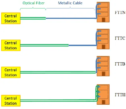
Since the end-point (end-terminal) of the fiber network varies, different structures have specific names. It is generally called, fiber-to-the-X. This “X” changes according to the end point of the fiber wire as shown in Figure 2-1.
6
Figure 2-1. Illustration of Fiber-to-the-X
If the fiber ends in the street cabinet, which is another telecommunication equipment including function-specific parts and acting as a central station, it is called fiber-to-the-node or –neighborhood (FTTN). On the other hand, if the cabinet is closer to the user’s premises; this is fiber-to-the-cabinet or –curb (FTTC). Although FTTN and FTTC are similar to each other, the distance to the premise node is much smaller in the FTTC. Typically, there is a 300 m-distance between a cabinet and the customer premise in FTTC. This distance is greater in FTTN. Fiber-to-the-building, -business, -basement (FTTB) is used for fiber connection up to the basement of a building. Full fiber Internet access exists in the fiber-to-the-home and fiber-to-the-desktop [2].
In telecommunication networks, the problem could be to design the network from scratch or to improve the existing network in terms of capacity or speed. Our problem is motivated from a real-world application of Turkish largest service provider. Due to the
7
competitive environment in the telecommunication market and privatization of big companies, a highly qualified, efficient and cost effective service in data communication is extremely important. The practice of the market leader is critical for today’s market share and will determine near future’s market positioning. Although in Turkey competitors are far behind the market leader in terms of data communication infrastructure, the investments show that market competitiveness will be more and more aggressive. Follower companies begin to work for their own infrastructure for small but potentially high return (profit) areas. Therefore, we specify our problem for both designing from scratch and for improvement in the existing network of the service provider. In our service provider application, there are two main categories for design: green field and copper field.
2.1. Green Field Problem Description
Green field refers to an area where the company has no infrastructure at all. In other words, there has been nothing constructed in terms of data wires so far in the region under consideration. This region will be served by the same service provider in terms of voice/phone services but nothing else. Hence, this region is convenient for making a design from scratch. Demands are assumed as known in advance and aggregated into demand points. Our aim is to provide high-speed Internet access in the demand nodes. In the green field, we consider building only an all fiber optical network due to the regulation of Information and Communication Technologies Authority in Turkey. According to the regulation, when a service provider enters a new region, it should serve all of its customers in the area with a fiber Internet access. This rule is to ensure that the given network will have the possibility to carry future demand and the capability for fiber expansion that may be encountered in the future. The aim is to construct the cost minimizing network so that all demand points receive service with required level.
8
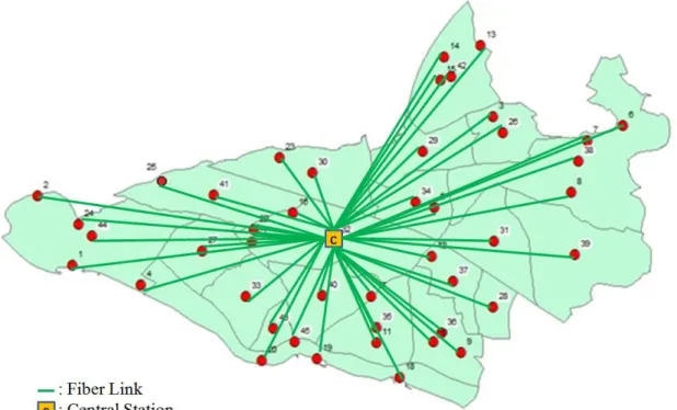
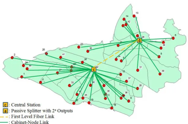
In fiber optic networks, especially in LANs, specific structures; i.e, splitters, are widely used. Usage of splitters allows carrying data in bulk up to a certain point of the “splitting” according to destination. In particular, passive splitters copy whatever data enters to the outgoing links. Hence, in all layers the same data transects. Also, passive splitters have a capacity of splitting. To this end, the aim of green field problem is to find the location of passive splitters, splitting numbers according to their capacities and interconnection of customers to passive splitters to reach the central station and the Internet at the end. Figure 2-2 is an illustration of a green field problem application.
Figure 2-2. Green Field Network Design Problem Illustration
In the particular setting under consideration, there is a central station at a fixed location. This central station serves both for voice communication and the Internet access. Each customer (as an aggregated unit) in the field needs to be connected to this central station with fiber links. The quality of the service is measured in terms of decibels (dB). The
9
company wants to offer services to all its customers guaranteeing a fixed level of dB service quality. Depending on the length of the fiber wire, dB decreases a fixed amount per km while reaching/getting closer to the customer. Direct connections to each customer from the central station will be too costly and thus, certain splitters are used. The company prefers to use passive splitters. The splitters have many types mainly depending on the available number of ports. The utilization of passive splitters also results in extra loss of dB. For example, in a passive splitter with 24 = 16 divisions, where the multiple of insertion loss in the port is taken as 3 dB, the total insertion loss in this particular passive splitter is calculated as 3 x 4 = 12 dB.
Another service quality criterion is the speed of the Internet access. The company under consideration wants to serve all customers with at least 100 Mb/sec bandwidth. The service provider determines this target value and specifies its central station’s output capacity as 2.5 Gb/sec. This power splits into fiber wires according to the splitting number of the passive splitter. For example, within a passive splitter with 16 outputs (24=16), the power is divided into 16 wires; i.e., 2500/16=625 Mb/sec. As expected, more splitting causes more decrease in the bandwidth value.
Thus, in the network design part of the fiber optic network design problem for this company, the problem is deciding on the location of passive splitters while obeying the dB requirements and bandwidth target values. The passive splitter type selection is another challenging decision to be made involving the tradeoff between the cost of the splitter, the splitting number, the insertion loss and the division in the bandwidth. More splitting increases reachability, but results in high losses. In addition to these insertion losses, we aim to serve all customers in a cost effective way. Hence, the objective is to minimize both fiber optical wiring cost and passive splitter costs.
As a result, the green field problem includes the selection of passive splitter locations, their splitting numbers and fiber links between demand nodes and passive splitters
10
including the central station. While minimizing the total cost function, the insertion loss requirement and bandwidth target value should be considered. Each passive splitter has a different number of outputs that it splits incoming fiber wire. The insertion loss depends on the passive splitter splitting number and the distance traveled beginning from the central station.
2.2. Copper Field Re-design Problem Description
The second problem type is about improving the existing telecommunication service in a region where we call “copper field”. The copper field is composed of some copper wires which are used for data transmission such as Internet access. These wires are copper or related types that allow normal speed Internet access. In order to improve the Internet access bandwidth, fiber wires could be used completely from the central station to the end-user or to a certain point closer to the end-user. Hence, data transmission is done with both fiber and copper wires. When we compare the fully copper networks, with the hybrid usage of fiber/copper usage, we see that the combination gives a quicker, safer Internet access and performs better. We wire fiber cables starting from the central station up to some point in the network and the remaining transmission is done via existing copper cables. Since data travels a smaller distance on the copper wires, the transmission speeds up, relatively.
11
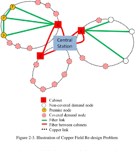
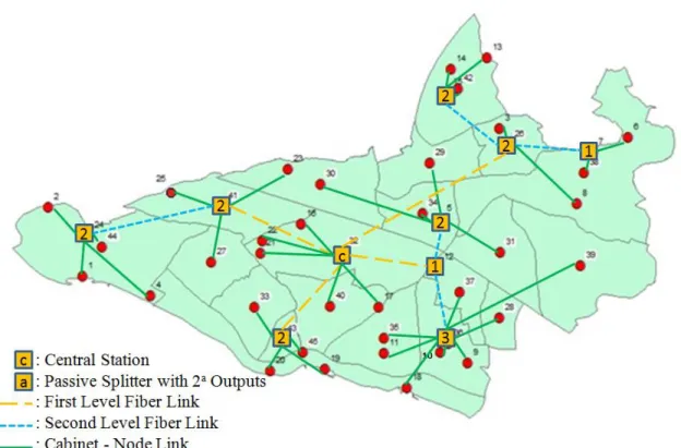
Figure 2-3. Illustration of Copper Field Re-design Problem
There is a central station which is already in use for Internet access via copper wires. The existing network consists of copper cables that make loops around the central station. There might be one or more copper cable rings around a central station depending on the geographical span of the region. Fiber wiring should start from central station and touch the copper loop(s) at some point(s) to improve the bandwidth. The point of touch of fiber wiring to the copper loop needs special equipment called “cabinet”. The cabinet acts as a central station and it is assumed that a cabinet provides
12
the same quality of service as central station does. It is also required that each cabinet is connected to the central station via two arc disjoint paths. This property comes out as a loop structure between cabinets including central station that is shown as the red line in Figure 2-3. In this manner, the central station can also be considered as a cabinet. In this way, we make sure that backbone network, which is the ring consisting of the central station and cabinets, can not be harmed.
If any demand node is in close proximity (say at most γ meters) to a cabinet over the copper wiring, the particular demand node is accepted as receiving fiber access service. In other words, each cabinet can serve its ring’s nodes if and only if the distance between the cabinet and demand node does not exceed γ value on its copper ring. Hence, demand nodes in neighborhood over the copper ring to the cabinet are assumed to have fiber service, which is called “covered demand node” in Figure 2-3. If a node is located further than value away from a cabinet, it is not considered as served by the cabinet; a direct fiber cable from the cabinet to this node is required. The green lines in Figure 2-3 represent such cases.
In the network design problem over an existing copper network, some customers may require additional services. Such customers are referred as “premise customers” by the company under consideration and they require a fully fiber path from a central station up to their building. In addition, premise nodes also require having a direct connection to at least one other premise node.
In the copper field network re-design problem; there is also a distance limit of the fiber access measured from the central station up to the end-user. This distance is a threshold for wiring fiber cable.
Our aim is to service all nodes with fiber connectivity by installing a minimum cost fiber network over the existing ones.
13
Chapter 3
Telecommunication Basics & Related
Literature
3.1. Telecommunication History & Basics
Communication is an essential need of humanity. Every society communicates with each other. Long distance communication was first tried in ancient Greek society [3]. Due to the lack of technical knowledge about electricity and light, they used human force. Optical telegraph was invented by Claude Chappe in France in 1793, and by Abraham Edelcrantz in Sweden in 1794. The optical telegraph working principle is sending light signals using series of equipment which act like mirror. After a few years, the optical telegraph became a nation wide used communication technology tool in Sweden and in France. The forthcoming discovery was electrical telegraph invented by Samuel Morse
14
in 1831. With the advent of electrical telegraph, the need for human force disappeared. Also, Samuel Morse is the father of simple encoding of its time’s alphabet by short, long and dot lines. Finally, Alexander Graham Bell invented the telephone in 1876, which allows voice transfer via electrical signal translations. These telephone networks are the preliminary forms of today’s telecommunication networks. In 1897, Marconi’s invention was another fundamental milestone in telecommunication network history. He invented wireless telegraphy by using electromagnetic waves. Another technological development was the transmission methodology changes. In 1960s, analog transmission left its place to digital signal transmission. This technology leads forward todays Internet. In 1980s, wireless telephone networks were a more and more used methodology. Then in 1990s, maybe the most important invention was made, namely, the optical transmission usage instead of electrical equipment. These introduced larger bandwidths, fast and secure Internet connections into modern life. A brief history of telecommunication networks is presented in [3].
For designing the infrastructure of telecommunication networks, many disciplines including operations research, computer science and electrical electronics engineering examine the problem within their own perspectives. Within the context of operations research, a telecommunication network consists of a set of nodes and links between some of them [4]. These nodes are demand points that send/receive messages or information such as voice, data, and video. The transmission is done via communication links [4]. The communication links can be copper cables (coaxial cable or twisted pair) fiber ones or both.
The telecommunication network structures are examined according to their levels. It is similar to the structure in the geographical classification; LAN connects some local nodes to an upper level which are nodes in the MAN and MAN is in fact a special detailed area in the WAN. Similarly, every multi-level network structure has an upper and a lower layer. Without loss of generality, we can define every network as/in terms of
15
backbone and access networks. The upper level is the backbone and the lower level is the access network. Any two consecutive layers in the hierarchy can be viewed as backbone and access networks.
When we look at this backbone/access network differentiation in terms of hub location, a telecommunication network consists of “tributary” and “backbone” networks. Hubs are switching points of the telecommunication traffic. Tributary networks (local access networks) connect demand nodes to hubs and backbone networks interconnect the hubs. In this definition, tributary networks can be “local” or “access” networks and backbone networks can be “hub-level” networks. Hubs are telecommunication elements such as switches, gates, concentrators, control points, or access points [4]. Some of the different electronic equipment may be exemplified as multiplexers, concentrators, or switches. The multiplexer collects incoming signals and composites the outgoing signal with higher frequency. Concentrators are like multiplexers, they compress incoming traffic and combine the outgoing signals. On the other hand, switching centers are points that remote switches have local switching functions to interconnect all users [5]. Even though the devices maybe different in each layer, we can view the system in terms of supplier – customer perspective in both backbone and access networks. Hence, suppliers are in the backbone network and customers are in the access one, even though the capacity, geographical area, and spanning region vary.
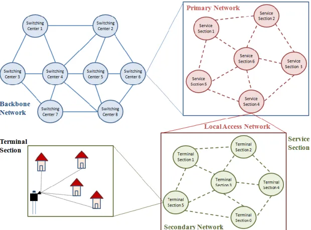
In general, the multi-level network structures include multiple levels which are connected to each other in a hierarchical manner. These levels may have different names in different literatures. In this thesis, we use operational research view and use this hierarchy in only two levels. For more general cases, Figure 3-1 shows the multi-level structure. The very up level is called backbone network. These links have high capacities and high transmission rates. The second level is the local access area. The connection is done via switching centers which are roots in the local access areas. In Figure 3-1, switching-center-6 consists of six service sections and these service sections constitute
16
the primary network. Each local access consists of several service sections. From service-section-4, we move to the third level of the network, which includes multiple terminal sections. The interconnection of these terminal sections defines the secondary network. Finally, each terminal section includes the territory network where the end-users are connected to the Internet [6].
Figure 3-1. Multi-level network
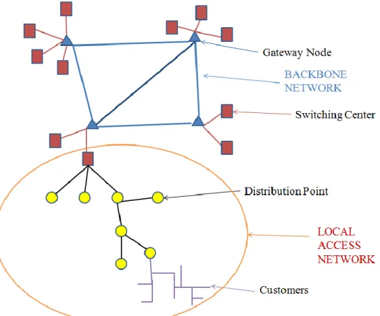
We now give more specific explanations based on Figure 3-2. At the highest level, which is the backbone network, nodes are called gateways. As explained before, the bandwidth between gateways is high and transmission rate in these links is also high. In
17
this figure, gateways have a fully interconnected topology. Gateways are points which spread connection to local access area via switching centers. Switching centers in this figure refer to the service sections in Figure 3-1. Then, the local access network starts. Distribution points can depend on the definition of the network and these might be junction points of highways or entrances of private areas. The network from distribution points to the end-customers is referred as the allocation area [5].
Figure 3-2. Hierarchical Structure of Telecommunication Network
The main difference of a backbone network is the high transmission rate over it. The backbone networks can have complete (fully-interconnected), ring or mesh topology. For fully-interconnected networks, the transmission is faster as expected, since there is a
18
direct link between each other [4]. However, it is not so cost effective. On the other hand, ring structure allows two arc-disjoint paths between two nodes to reach each other. When there is a failure in one of the links, the other path can be used instead. Thus, survivability is achieved in the ring structure [7]. Mesh networks have connected topologies where at least one direct connection is missing [4].
Since our problem definition emerges from an application from Turkey’s largest service provider, we will be referring to these switching centers as central stations in their terminology in the rest of this thesis. As explained in Chapter 2, our scope is the local access network including a central station and its corresponding distribution points.
3.2. The Telecommunication Network Design Problem
In the OR literature, the telecommunication networks design problem (TNDP) is defined as finding a suitable configuration of nodes and links, so as to satisfy the traffic demand between nodes [6]. The objective of TNDP may be to minimize the cost or minimize / maximize certain performance measures. Costs include the installation and operation costs of new devices such as concentrators or switches. On the other hand, the performance measure can be reducing network congestion, routing the traffic, and other similar operational decisions [6].
The TNDP can consider either a network design from scratch, i.e. there is nothing in the beginning in terms of communication, or an expansion/improvement over the existing network. If there is no network in the beginning, the overall aim is a network with telecommunication elements in a cost-effective way considering demand points, technical specifications, and equipment capacities. The expansion of the existing network may include capacity expansion by adding new links, by changing the existing
19
technological infrastructure or an improvement of the existing network by restoration of equipments [8].
In both expansion and designing from scratch cases, the resulting networks have many evaluation criteria. These criteria are network cost, capacity, reliability, performance, and demand pattern [4]. The cost of a network includes establishing a link, using a link dependent on the usage volume, establishing a hub, using a hub as in [9]. Usage costs are actually depending on the amount of flow. Capacity of networks contains both link capacities and hub capacities. Performance depends on technical capabilities of telecommunication hardware and software elements. Performance can be evaluated when the amount of traffic in the network arises over time and when the network can handle the increased amount of traffic. Demand pattern may be many-to-many, i.e., any node can have traffic with any other node in the network or many-to-one, i.e., every node will have connectivity to a central location existing in the networks [4]. The survivability is an important issue in telecommunication networks. Especially in backbone networks, any failure in the link may cause critical service problems. The reader can refer to [10, 11, 12, 13, 14] for further details. In the reliability issue, the network may use homing to multiple hubs which allows a node to have a direct link to more than one hub node. If there is only a single hub, the problem is called single homing. Also, alternate routing is used in backbone networks. In this type, there is more than one path between each hub node which has sufficient capacity [4]. Thus, rerouting is possible when a failure occurs. Also, reliable p-hub location problems are developed as p-hub maximum reliability and p-hub mandatory dispersion models in [15].
There are different types of problems that consider (i) solely tributary or (ii) solely backbone networks as well as (iii) joint problems which evaluate backbone and tributary together. Since the telecommunication network problems are complex in general, a typical researcher divides the core problem into subproblems and solve them subsequentially [16]. The subproblems are generally NP-hard [17].
20
We now provide the relevant literature under each heading, namely local access network design, backbone network design and joint network design separately.
3.2.1. Local Access Network Design Problem
According to [6], there are four main problem types in local access network design. The first is (i) concentrator location problem which decides on the number and location of concentrators. There is a fixed installation cost, assignment cost and capacity of new concentrators. The problem seeks concentrator locations with assignment of terminals to the selected concentrators while minimizing total costs and obeying capacities [18]. The second one is (ii) terminal assignment problem which is about concentrator- terminal matching. The third problem type is (iii) terminal layout problem. In this one, it is assumed that original network has all the available connections and given the terminal- concentrator assignments, the objective is to find the best network topology to connect each concentrator to its assigned terminal. The last one is (iv) Telpak problem, which is about the link capacities. Terminals and end users generate/receive different amounts of traffic according to the distance to the switching center. Even if terminals are identical, closer ones carry higher load than further links. Hence, there is a variety in loading capacity of the links. This problem is about minimizing network link costs while satisfying traffic requirement and selecting link capacities in a tree structure [16]. It is originally discussed in Rothfarb and Goldstein [19] and is known in the literature as the one-terminal Telepak problem. Several heuristics have been developed for the problem by Goldstein [20], Hansler [21], Chandy and Russell [22]. The main characteristics of the problem are explained in [16, 5, 23]. In [5], local access network expansion problem is discussed. The paper is mainly about the capacity expansion of the network and the problem is formulated as a minimum cost multicommodity network flow problem.
21
In the analyses of telecommunication elements, there are several evaluation criteria. The facility type is one of the important characteristics of a telecommunication network design problem: they might be single facility or multi-facility. Also, the design problem may be for a single representative period, which is referred as the single-period or the problem may include designing within time intervals, which refer the multi-period models. The topology of the problem may be fully-interconnected, ring, star, tree, mesh. The topology issue is a restriction in some cases. Also, flow pattern is important in some networks. If there is more than one origin destination pair in the network, then flow pattern is multi commodity. The capacity of transmission links or hardware characteristics defines the capacitated problems. In the uncapacitated problems, the cost of links and hardwares are considered.
Table 3-1 provides a snapshot of the characteristics of local access network design problems according to the facility type, period, topology if it exists, flow pattern and capacity.
22 Table 3-1. Local Access Network Design Problem
Local Access Network Design Problem
Facility
Type Period
Topology
Flow Pattern Capacity
Solution Methodology / Notes
Single Multi Single Multi Single Com.
Multi
Com. Uncap. Cap. [50]
(Bley and Koch, 2002)
√ √ Tree √ √
Backbone and local access design are formulated separately. Sequential solution procedure is used. Integer linear programming
techniques are proposed.
[5]
(Balakrishnan, 1991)
√ √ Tree √ √
Modeled as a minimum cost multicomodity flow with gains problem. It is a
capacity expansion problem. [25] (Chamberland, 2010) √ √ - √ √ [16] (Gavish, 1991) √ √
Tree-Ring √ √ Heuristics are proposed.
[24]
(Frantzeskakis and Luss, 1999)
Mixed integer model and a heuristic algorithm are
proposed.
23
In the local access network design problem, there are redesign and update problems. Redesign is motivated to reach a desired level of capacity while using existing capacity. An example is in [24], which is local access redesign problem and modeled as mixed integer problem (solved by a heuristic algorithm). In this network redesign problem, the motivation rises from the annually leasing facilities of large telecommunication companies to other carriers in some areas. Although using the existing service system was a cost-effective structure at the beginning, as demand increases over time, the service quality between the source-destination pair in the embedded network may become insufficient. Thus, this problem attempts to find optimal network structure to serve existing and new demands given certain existing facilities, and routing assignments. At the end, some existing facilities may be disconnected or utilized differently and new facilities may be constructed with routing structures for new demands. [24] provides a mixed- integer program (MIP) which is solved via a software package and heuristic algorithm.
On the other hand, network update problem is usually proposed in terms of technological specs of the infrastructure. In Chamberland [25], the update problem is considered to satisfy new demands for existing subscribers. The subscribers may prefer to use/buy new service equipment as technology develops such as high-definition televisions working over the Internet. In order to satisfy this demand, the architectures may need to be changed. A mixed integer programming model is developed and a tabu-based heuristic algorithm is proposed.
For further information about local access networks, the reader can refer to surveys [23, 26]. For earlier works, the reader can refer to [16, 5, 27].
24
3.2.2. Backbone Network Design Problem
In general, backbone network design problem decides (i) location of backbone nodes, (ii) processor/equipment used in these backbone nodes, (iii) routing and capacity assignments via linking backbone network nodes and building a route between them. Generally, backbone networks have many-to-many structure. In other words, there are several sources and destination nodes, hence traffic flows from many different sources to many different sink nodes. Therefore, the backbone network problem is generally modeled by using minimum cost multicommodity network flow problem which minimizes a cost function while routing the commodities over a capacitated network. In the telecommunication applications, the model may include time-delay and reliability requirements. The requirements may differentiate according to the priority requirements [28]. Also, if there is a predetermined topology, the topological constraints need to be obeyed.
25 Table 3-2. Backbone Network Design Problem
Backbone Network Design Problem
Facility Type Period
Topology
Flow Pattern Capacity
Solution Methodology / Notes
Single Multi Single Multi Single Com.
Multi
Com. Uncap. Cap. [31] (Altınkemer and Yu, 1992) √ √ - √ √ Lagrangian relaxation based algorithm is proposed. [34] (Din, 2008) √ √ - √ √ The metaheuristic: simulated annealing is used to find near optimal
solutions [11] (Ho and Cheung, 2007) √ √ - √ √ Generalized survivable network is modeled [12] (Ho et al., 2006) √ √ - √ √ Generalized survivable network is modeled [30] (Kershenbaum et al., 1991) √ √ Mesh √ √
Local search heuristic algorithm (MENTOR) is proposed. [35] (Pierre and Elgibaoui, 1997) √ √ Mesh √ √
Delay & reliability of the network is considered. Tabu search which is a metaheuristics is used.
2
26
Backbone Network Design Problem
Facility
Type Period
Topology
Flow Pattern Capacity
Solution Methodology / Notes
Single Multi Single Multi Single Com.
Multi
Com. Uncap. Cap. [36]
(Konak and Smith, 1997)
√ √ Mesh √ √
Delay & network reliability are considered. Evolutionary
algorithm which is a metaheuristic is used. [29] (Gerla and Kleinrock, 1987) √ √ Mesh √ √
Delay & network reliability are considered. Minimum Cost Multicommodity Flow
Problem is utilized.
[13]
(Alevras et al., 1998)
√ √ - √ √
A cutting plane algorithm combined with linear
programming based heuristics is proposed. [40] (Chen and Tobagi, 2007)
√ √ Complete √ √ Heuristics are proposed.
2
27
In the backbone network design problems, OR literature shows that there are different types of solution techniques including heuristics, such as branch exchange, concave branch elimination or cut saturation [29, 30, 31]. MENTOR, which is a heuristic method is proposed in [30] and a lagrangian relaxation is used in [31]. However, due to curse of dimensionality, problems may be difficult to solve [32]. Also, other techniques are used as simulated annealing [33, 34], tabu search [35], evolutionary algorithms [36, 37, 38], ant colony optimization [39] and heuristics [40, 32]. For earlier studies about the backbone network design, the reader can refer to [41, 32, 42, 43, 44, 45, 46].
3.2.3. Backbone and Local Access Network Design Problem
The last problem type is on the joint networks which include both backbone and access network at the same time. We refer to this type as hierarchical design as in the cases in [47, 48, 49]. Since two-level hierarchical network design problems include many decisions, it may be divided into some sub- problems. According to [47], these subproblems include (i) hub location problem, (ii) clustering of nodes, (iii) interconnection of nodes in the backbone and cluster networks, (iv) routing in the backbone network and then cluster networks. Note that these subproblems are actually similar to the solely local access or solely backbone network design problems.
28 Table 3-3. Joint Network Design Problem
Multi-level Network Design Problem
Facility
Type Period
Topology
Flow Pattern Capacity
Solution Methodology / Notes
Single Multi Single Multi Single Com.
Multi
Com. Uncap. Cap. [67] (Proestaki and Sinclair, 2000) √ √ Ring - Ring √ √
The partition, construct and perturb network design method is used. For small problems, optimal solutions
are obtained. For various network, heuristic results are
shown. [66] (Labbe et al., 2004) √ √ Ring -Star √ √ Polyhedral-based exact algorithm and branch-and-cut algorithm are proposed.
Up to 300 vertices can be solved optimally.
[64]
(Petrek and Siedt, 2001)
√ √ Star - Star √ √ It is used for GSM networks.
[48]
(Thomadsen and Stidsen,
2007)
√ √ Mesh √ √
Models general fixed charge network design problem. Branch and cut and price algorithm is proposed.
2
29
Multi-level Network Design Problem
Facility
Type Period
Topology
Flow Pattern Capacity
Solution Methodology / Notes
Single Multi Single Multi Single Com.
Multi
Com. Uncap. Cap. [49] √ √ - √ √ A dynamic algorithm is proposed. (Rosenberg, 2005) [68] (Thomadsen and Larsen, 2007) √ √ Complete - Complete √ √ Decomposition, column generation and
branch-and-price algorithms are used.
[65]
(Labbé and Yaman, 2008)
√ √ Star - Star √ √
Facet-defining inequalities are proposed and branch-and-cut is used. Heuristic
based on lagrangean relaxation is also proposed.
[69] (Kramer and Pesavento, 2002) √ √ Complete - Complete √ √ Parallel evolutionary algorithm is proposed. [70] (Yaman and Carello, 2005) √ √ Complete - Star √ √
Modular link capacities are used. Both exact and heuristic methods are used.
2
30
In hierarchical networks, there are different methods for formulation and solution methodologies. For instance, mixed-integer problem (MIP) formulation, which decides on locations of hubs in the backbone network and routing for each cluster, is used in [48]. According to [48], the hierarchy of the telecommunication network allows us to use the economies of scale methodology in the backbone networks by utilizing the high speed network in the central side. The mesh network topology for the backbone network is used and it includes interconnection of the given clusters. The problem is called generalized fixed-charge network design problem. For the MIP, a branch-cut –and- price algorithm is proposed. On the other hand, in [49], Rosenberg proposes a dynamic programming algorithm for interconnection of a number of nodes.
In [50], Bley and Koch study the nation-wide communication network which includes both access and backbone networks. In the backbone network, there are survivability and routing constraints. The model aims to find assignments between nodes and layers by considering node locations, demands, possible connections and some other technical constraints. A MIP is proposed which selects which node should belong to which layer while each node needs to be connected to its layer and to the next layer via a tree structure.
Generally, multi level, which means with more than 2 levels, network design problems are examined as a hub location view in OR literature [51, 52]. More general surveys include [53, 54, 55, 56, 57, 58, 59, 60, 61, 62]. Also [63] Yuan gives an annoted bibliography over telecommunication networks.
Klincewicz [4] studies the two-level hierarchical network in its survey. There might be same or different topologies in each level, examples of which are star - star [64, 65], ring - star [66], ring - ring [67], complete - complete [4, 68, 69], complete - star [70] or mesh -mesh [71].
31
The joint network of fully interconnected backbone and access network is defined in [4] and called fully interconnected network design problem. In [69], network is designed from scratch and the problem is solved via parallel evolutionary algorithm which uses clustering rather than match hubs with corresponding access networks. In [68], numbers of clusters and the number of nodes in the clusters are predetermined. It is modeled as a mixed integer programming problem and solved via decomposition, column generation and branch-and-price.
Another type of two level hierarchy is as follows: a fully interconnected backbone network with a star topology in access network arises in [70]. This problem is modeled as a capacitated single assignment hub location problem with modular link capacities. Since link capacities are modular, the cost of an edge is not linear but stepwise. Also, another special assumption of [70] is the capacity restrictions on traffics. Here, the capacity of a hub is the amount of traffic transiting through the hub instead of incoming traffic. This model allows only single homing, which means that each node is related to exactly one hub. In [72], the same problem type is modeled as a capacitated single allocation hub location problem. Also, single homing, double homing with free pair and double homing with fixed pair cases are examined. Two level local search approach is used for solution methodology (initial solution, optimization step and post optimization step).
Another possible topology that is considered in the literature is the ring-star structure. In this type, each transit node is connected to one hub node. For example, in [66] ring structure represents the internet and star topology is the intranet (assignments). Here, the problem is solved via a branch-and-cut algorithm.
In the star-star topologies, both backbone and access networks are in the star structure. This topology is similar to a special case of green field model explained in Chapter 2 (with two levels- with single level passive splitter usage). In [65], the problem is
32
modeled as uncapacitated hub location problem. Hubs are directly connected to a central station and each terminal node is directly connected to a hub. In the solution methodology, branch-and-cut is employed. Heuristics based on lagrangean relaxation are developed. Another star-star topological problem is investigated in [64] which simultaneously solves concentrator quantity problem, concentrator location problem and assignment problem. Since even special cases of this problem are NP-hard and can not be solved optimally for the large networks, a high complexity algorithm is proposed. The ring - ring topology in [67] considers multiple interconnected rings. Total ring length and intra-ring traffic are constraints for the problem. The proposed routing algorithm’s objective is to minimize the maximum flow on the rings especially for designed for dual homing structures.
Recall from Chapter 2 that in the green field, designing the network from scratch, the goal is to reach every customer in a cost effective way by utilizing passive splitters. From a given central station node, the model decides the location of passive splitters, their types and assignment of demand nodes to passive splitters while obeying bandwidth and insertion loss requirements. The green field network design problem has a multi –commodity flow pattern. Since passive splitters have a limited outgoing fiber, the problem is capacitated. Similarly, different passive splitter types show the multi-facility type and we design for a single period. For the green field, the network is a rooted tree – star structure due to the fact that there is a single central station. And the connection of passive splitter to this central station results in a tree structure that is rooted from central station. At each passive splitter, demand nodes are connected to the splitter with star topology. Since we do not know in advance the number of level in the embedded tree network, the problem definition differs from the ones in the literature. Our copper field re-design problem is about an improvement in the network. The infrastructure of given network consists of copper loops that are connected to the central
33
station. In the re-design model we determine the location of cabinets in these copper loops and connect the cabinets with central station in a ring structure. Also, additional fibers installed depend on the γ value coverage threshold. Besides these fiber links, the premise nodes are linked to the nearest ones. Therefore, it seems to have a ring-star structure when γ is zero and have a specialized structure in the other cases. Also, the premise node’s specific requirement differentiates the problem from the existing ones in the literature. Remaining characteristics includes multi-commodity flow pattern and single facility type since all cabinets are homogenous.
34
Chapter 4
Model Development
The proposed problems consider designing the infrastructure of fiber optical network of the service provider company. In order to find possible solutions to our problems in the green field and the copper field, we formulated mixed integer mathematical models. In both problems, we wish to install fiber optic wires to provide service in a cost effective way. The data specific to each problem is attained after numerous discussion sessions with the service provider.
4.1. Green Field Model Development
In the infrastructure of designing from scratch, we know the central station location in advance. We assume that distribution points are aggregated forecasted demand locations
35
to which high bandwidth Internet access should be served. In this network, we need to find passive splitter locations to diminish fiber optical wire usage. Since we wish to reach each demand node, to put passive splitters in the same location with a demand node decreases surplus usage of wires. Hence, without loss of generality, we assume that demand points are possible passive splitter locations. Let be demand node set on a network including a central station which is referred as .
Different passive splitter types are considered in the system and so, we use a set for defining these different passive splitters. Let be the set of passive splitters’ types. The first type passive splitter is solely used for the central station and for the remaining ones the output number is a function of parameter , e.g., is the 3rd type passive splitter with outputs or is the passive splitter with outputs.
In the infrastructure, wiring can be applied in the roads including junction points corresponding to corners of streets or entrance of private areas. Therefore, we use highway and street distances in the system. shows the highway distance from node to node . Since we aim to minimize the cost, we include the fiber optical wire cost in the function. Then, shows the cost of shortest path from to .
Also, the passive splitter usage incurs a cost to the service provider which includes purchasing, setting, operating and maintenance costs. The cost of a passive splitter depends on its type. We let show the cost of kth type passive splitter where . As technological developments increase and the specs improve the cost of a passive splitter may vary. To this end, we define a parameter α corresponding to the proportion between the splitter and wiring costs. This proportion allows us to make a comparison for different cost structures of the fiber optical wiring and passive splitters.
36
As explained in problem definition part, each passive splitter usage causes an insertion loss according to its splitting number. Since the dB loss depends on the passive splitter type, we denote the port number in the splitter by parameter . For example, if the model uses a passive splitter with 8 = 23 outputs, then the model uses splitter type , the number of ports is . The insertion loss in each level of port is specified with parameter , which is fixed at 3 dB for each port by the service provider. For example, in a passive splitter with 4 outputs, the insertion loss in the passive splitter is 6 dB, as shown in Figure 4-1.
Figure 4-1. Insertion Loss Illustration in 1:22 Passive Splitter
Similarly, the insertion loss per km is another power loss in the system, which is given as 0.2 dB/km by the service provider and is defined as parameter in our model. The insertion loss budget is given as 28 dB by the service provider, but in order to generalize the model formulation, we define parameter for threshold value loss. For simplicity, we assume that a signal starts at the central station with zero dB and each fiber optical wire length augments the dB amount. Also, passive splitters make contribution to that amount. Thus, every node need to be in this 28 dB, namely , radius.
The speed of Internet can be measured by download/upload speed as seen in the problem definition part. Therefore, we consider the service quality of the company by the
37
download speed measured by Mb/sec. The out power of the central station is determined by which is specified as 2.5 Gb/sec in our application. The aim of the service provider is to provide at least 100 Mb/sec download threshold for each distribution point, customer, in our models. This specification is also affected by the number of ports in the passive splitters. More splitting causes more reduction in the speed. This 100 Mb/sec service quality is defined as in the model.
Figure 4-2 visualizes the change in dB and Mb/sec, where the parameters assumed as follows: central station starts with 0 dB and the power of central station is 1000 Mb/sec. The insertion loss during the way is 2 dB/km where the insertion loss multiple in the passive splitter is 3 dB. Additionally, the insertion loss budget is 30 dB.
38
As shown in Figure 4-2, the insertion loss of the passive splitter with 22 outputs has both insertion losses during the way and in the passive splitter. Then, insertion loss is 2
(dB/km) x 3(km) = 6 (dB) during the way and additionally 3 x 2 = 6 dB in the passive
splitter, which results with 6 + 6 = 12 dB. For the second passive splitter, we add 2 x 2
= 4 dB during the way and 3 x 3 = 9 dB in the passive splitter. When we add these 4 dB
and 6 dB to the previous passive splitter’s insertion loss amount, we get 12 + (2 x 2) +
(3 x 3) = 25 dB.
To summarize, sets, matrices and parameters are as follows:
Set of demand nodes
Set of passive splitter type Shortest distance matrix Cost matrix
port number in the passive splitter, Central station
Proportion between cost of fiber link and cost of passive splitter Insertion loss through the fiber link
Insertion loss in passive splitter Insertion loss budget
Bandwidth at central station
Required bandwidth at each demand node
The objective function includes both passive splitter usage cost and fiber optical wiring cost. By deciding on the passive splitter location, the splitter number in it and fiber optical wiring pairs, we satisfy the bandwidth requirement and dB loss restriction. So, we need to know pairs of nodes with the fiber optical wire connection and passive splitter’s location with its type. Decision variables are as follow:
39
: the speed at the node in terms of Mb/sec : the dB amount at node
The proposed model is as follows:
(4.1.1) (4.1.2) (4.1.3) (4.1.4) (4.1.5) (4.1.6) (4.1.7) (4.1.8) (4.1.9) (4.1.10)