PHYSICAL REVIEW B VOLUME 48, NUMBER 4 15JULY 1993-II
Fano
resonances
in
quasi-one-dimensional
electron
waveguides
Erkan Tekman* and Philip
F.
BagwellSchool ofElectrical Engineering, Purdue University, West Lafayette, Indiana $7907 (Received 19November 1992;revised manuscript received 11February 1993)
In the spectroscopy of atoms and molecules, an asymmetric Fano resonance arises whenever a bound state associated with one electronic configuration is coupled to the ionization contin-uum of a different configuration. A strikingly similar resonance appears for electronic transport in conductors with more than one subband, independent of the specific details ofthe system under study. We develop a two-subband approximation which describes the Fano resonances for conduc-tion through an electron waveguide containing donor impurities, for
I
—
X
—
I'intervalley tunneling in a GaAs/Al Gap As/GaAs heterojunction, and for an electron waveguide coupled toa resonant cavity. Interference between the direct and intersubband transmission channels gives rise to the asymmetric Fano resonance.I.
INTRODUCTION
Atoms and molecules have different electronic con-figurations. In the simplest treatment of an atom or molecule these different configurations do not interact, and their Schrodinger wave functions are approximately orthogonal. For certain transitions between high-lying energy levels, however, the electron-electron interaction between these different electronic configurations must be taken into account. The most interesting type of such a "configuration interaction" arises when one
of
the states belongs
to
an ionization continuumof
en-ergy levels, while the other isa
discretestate.
An elec-tron in such a boundstate
can then decay into the continuum, moving away from the atom or molecule. Fano~ showedthat
the asymmetric resonances observed in the inelastic-scattering spectra oflight and electrons from atoms and molecules arise from these autoioniza-tionstates.
The same type of scattering resonances arise in nuclear physics.Recent theoretical studies
of
electron scattering from donor impurities in quasi-one-dimensional (quasi-1D) electron waveguides4 s have revealed similar asymmet-ric resonance structures for conductance as a functionof
Fermi energy (or channel width). These asymrnet-ric resonances appear whena
continuum level from one subband is degenerate in energy with aboundstate
sup-ported bya
diff'erent subband, very similarto
the atomic autoionization resonances. References 7—9 pointed outthat
the same asymmetric resonance feature also ap-pears in other, seemingly unrelated physical systems. In additionto
scattering from donor impurities in an electron waveguide, the scattering from an oscillating barrier, optical absorption or electronic transport in"type-II"
GaAs/Al~Gaq As/GaAs heterojunctions, transmission througha
waveguide linkedto a
resonant cavity, ' transmission througha
quantum-dot inmag-netic field, and conduction through an array
of
disor-dered quantum wires~s all display the Fano resonances.Each of these systems contains two different scattering channels, one belonging
to a
continuum and the otherto
a
boundstate.
In this paper we analyze the Fano resonances in quasi-1Dsystems. In Sec.
II
we developa
two-band model for the electronic transport in quasi-1D systems. SectionIII
applies this two-band modelto
scattering from a donor impurity in an electron waveguide, 4 s tunneling through an Al Gaq ~As barrier, and transmission through a waveguide linkedto a
resonant cavity.~~ ~s InSec. IV
weanalyze how the Fano resonances are modified in more realistic, multiple-subband systems.
II.
THE
TWO-BAND
APPROXIMATION
The Schrodinger equation describing scattering in a quasi-1D electron waveguide is
(
—
V'+
V.(y)+
V..
(x,
y))
C(x,
y)=
EC(x,
y),(2.1)
where V,(y)isthe confining potential in the lateral direc-tion andV„(x,
y) is the potential dueto
the scattering center. The geometry is shown inFig.
l.
We assumethat
the confining potential is uniform along the prop-agation direction, since any inhomogeneity can well be represented by an effective scattering potential. 7We are interested in scattering solutions@(x,
y) for an electron wave incident froma
single subband on the scatterer. Asa
result, there will be both transmitted and refiected waves, which may be either propagating or decaying as they move away from the scatterer.For arbitrary
V„an
analytical solutionof Eq. (2.1)
is not possible. Therefore, we makea
simplifying assump-tionthat
the scattering potential is extremely localized along the direction of propagation,that
is,(2.2)
2554 ERKAN TEKMAN AND PHILIP
F.
BAGWELLquire Kq
)
0to
keep the wave function finite as ~x~—
+oo.) The conductance is given by G=
~Tqq~ for sq &E
&e2. There exist three special points forthe conductance G (orequivalently Tqq) in the complex energy plane; where G (a) is zero, (b) isunity, and(c)
has a pole.~s InvertingEq. (2.
5) showsthat
the transmission zero, Tqq=
0, is determined from202K2
+
V22—
—
0.
Unity transmission amplitude Tzp
—
—
1occurs when (2.6)2K2+
V22 ——11 (2.7)
FIG.
1.
Transmission through adonor impurity in an elec-tron waveguide. Aquasibound state produced near the locally attractive donor potential gives rise toPano resonances in the waveguide conductance.where v(y) is an arbitrary function of the lateral coordi-nate.
By
expressing the scattering wave function@(x,
y) in terms of the eigenstates(P~j
of the confining po-tentialV„Eq.
(2.1) can be convertedto a
set of linear equations. The resulting matrix equation is2~2+
V22 ———
2zkg
+
Vjg (28)The poles ofTqq or G define the bound and quasibound states of the system as discussed in Ref.
7.
III.
EXAMPLES
OF
FANORESONANCES
A. Donor
impurity in anelectron
waveguide The transmission pole Tqq —+ oo exists at the complexenergy satisfying
[
—2iK+
V]
T
=
—
2iK,
(2.
3)where
K
is the diagonal matrixof
wave vectors K k 6„=
(E —
s ) ~6'~„,
V
is the interbandtransi-tion matrix having elements V
„=
(P ~v(y)~P„),andT
is the matrix ofwave-function transmission amplitudes. The subband energiese~
correspondto
the eigenstates The conductance can be calculated from the two-terminal Landauer formula,This problem has been studjed previously ' ' jn
the context
of
scattering inquasi-1D systems.By a
donor impurity, we mean that v(y) inEq. (2.
2) is negative as shown inFig.
1,
sothat
Vj~ & 0 and U22 &0.
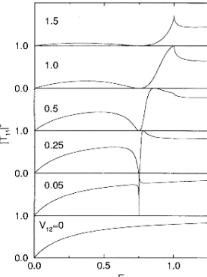
The predicted transmission ~Tqq~ from the two-band modelis shown in
Fig.
2. The asymmetric Fano resonance1.5 (2.4) 1.0 1.0
—
2xkg+
Vjg Vg2 Tgg V21 2K2+
U22 T21(2.
5)where the inverse decay length e2 is k2
=
iwq. (We re-where the m and n are summed only over the propagat-ing subbands. HereT~„denotes
the amplitudeof
the transmitted wave in the mth subband resulting from an incident wave in the nth subband. The unit of conduc-tance inEq. (2.
4) is 2e2/h.The transmission amplitudes
T
can be extracted fromEq. (2.
3) by inverting the matrix on the left-hand side. We do not discuss this general problem, since it usually requires numerical matrix inversion and has been studied by others.s 7 The simplest approximationto Eq. (2.
3)isto
neglect all but two subbands and solve the resulting2x2
matrix equation. When e~ &E
& e2, sothat
the only incident wave is in the lowest subband, the reduced matrix equation for our scattering problem is0.5
=
1.0 I— 0.0 1.0 0.0 0.0 0.5 1.0 EFIG.
2. Transmission probability as a function ofenergy for a donor impurity in an electron waveguide. A clear Fano resonance develops for weak intersubband interaction(V&2
=
0.05), and gradually distorts as the intersubbandscattering (Vj2
=
V2q) increases. The two subband energies are eq—
—
0 and t'2—
—
1.
The potential matrix elements are +11—
+22—
1~PANO RESONANCES IN QUASI-ONE-DIMENSIONAL.
. .
2555 is observed most clearly belowa
new subbandopen-ing when the intersubband matrix element Vi2 is weak (Vi2
=
0.
05).
We now analyze the two-subband modelto
explain all the qualitative features
of Fig. 2.
In the absence of any intersubband interaction, the transmission amplitude
Tii
fromEq. (2.
5) isEB
V»
2iki
(3 1)
GaAs Al-Ga-As GaAsThere is also a bound
state
in the second subbandat
an energy given byEq. (2.
6).
We can writeEq. (2.
6)asKq=
—
V22/2, which correspondsto
an energyE
=
E2EQ.
The binding energy is
E~
=
(Pz) . Dueto
absenceof
interaction, this bound
state
is equivalentto that
found for a strictly 1D problem. Therefore, in the absence ofintersubband interaction, we have two typesof
states below tq. scattering states from the first subband and abound
state
from the second subband.The shape of the transmission resonance is deter-mined by interference between the direct and intersub-band transmission channels. Turning on the interaction between the subbands, the transmission amplitude be-comes
+
Ti
i Tqi 4ikg(3.
2)B.
X
valley tunneling in Al Gaq AsA 1D band diagram for an Al
Gai
~As barrier be-tween two GaAs electrodes is shown in Fig.3.
By
ap-propriately choosing the composition ratioof
the barrier In additionto
the direct transmission via the first sub-band (the first term), one has transmission mediated by the second subband (the secondterm).
Notingthat
1/Tii
has a negative imaginary part (when Vii(
0),
one easily finds destructive interference between the di-rect and intersubband transmission channels below the bound-state energy, i.
e.
,for K2)
P,2 For energ. ies abovethe bound state, the wave interference is constructive. At the bound-state energy the second term in
Eq.
(3.
2) diverges, thus transmission vanishes.As one further increases the energy beyond the bound
state
(decreases Kq), unity transmission is obtained at a wave vector given byEq. (2.7), that
is, rc2=
K2+
(~V2i
/2Vii).
For very weak intersubband scattering, V2i 0, the transmission zero and unity transmission occur at almost the same energy. This gives the charac-teristic Fano line shape for the asymmetric transmission resonance. Stronger intersubband scattering increases the separation between the transmission zero and unity transmission points. When ViiVz2=
~V2i~, the case for a h-function scatterer in the lateral direction, s unity transmission takes place exactlyat
the onsetof
prop-agation for the second subband. A further increase in~Vqi~ /Vi
i,
suchthat
the second subband becomes prop-agating where unity transmission should occur, removes the unity transmission point altogether.FIG.
3.
Conduction-band edge for a GaAs-Al Gaq As-GaAs single barrier tunneling structure. The alloy composi-tion ratio in the barrier is chosen so that the A valleymini-mum is lower than the I' valley minimum in the barrier, pro-ducing aquasibound state in the barrier.
alloy, the
X
valleys can lie below theI'
valley in the bar-rier. The transmission probability through such a bar-rier has previously been calculated. ~It
was foundthat
the transmission probability has asymmetric resonances, which were attributed
to
Fano-type effects.Our two-band model may be used
to
approximate the tunneling through an AlGai
~As barrier. Since the present treatment is only a crude approximationto
the realistic problem, we intend no quantitative comparison with Ref.11.
For example, our model completely ne-glects the effectof
the underlying atomic structure, con-sidered through the use of the Bloch states in Ref.11.
In addition, the 6 potential inEq. (2.
2) is only an approx-imationto
the actual conduction-band structure. Nev-ertheless, we believe our two-band model captures the essential physics ofI'
—
X
—
I
intervalley tunneling.The only essential difference between scattering from
a
donor impurity in
a
waveguide andI'
—X —
I'
intervalley tunneling isa
sign change of the intrasubband matrix el-ementV».
Since the barrier potential isrepulsive fortheI
valley, we have V» &0.
The potential is stillattrac-tive forthe X'valley, so
that
V2z(
0 asbefore. Changing the signof
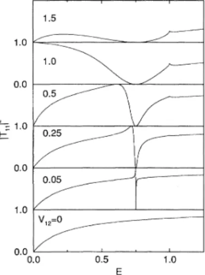
Vii reverses the condition for destructive and constructive interference between the direct and inter-subband transmission. This sign change therefore "in-verts" the Fano resonance, as shown inFig. 4.
Equation(2.
7) still describes the pointof
unity transmission, andEq. (2.
6) still determines the transmission zero.But
the unity transmission point now occurs at a lower energy than the transmission zero. (The unity transmission ob-tained atE
=
0 for Vjg—
—
1.
0 inFig.
4 is an artifact of the two-band approximation, which disappears when other subbands are taken into account.)One shortcoming
of
our two-band model isthat
more sophisticated calculations observe both types of Fano resonances shown in Figs. 2and4.
This shortcoming is a consequence of our disregarding any crystal structureat
the atomic scale. The form of the Bloch wave functions used in Ref.
11
(taken asa
basis in whichto
expand the tunneling wave functions) may give riseto
both positive and negative potential matrix elementsV».
The result-ing resonance structure may vary therefore between Figs. 2 and4.
2556 ERKAN TEKMAN AND PHILIP
F.
BAGWELL 48 1.0 0.0=
1.0 0.0 1.5of
the Schrodinger equation fora
network of quantum wires given in Ref. 24. Assumingthat
only the lowest subband is populated in all the wires (i.e.
, using strictly1Dwires instead of
@1D
ones), the wave function is equalto a
scalar wave function Q, along each edge eof
the network. These functions are determined by the match-ing conditionsat
the vertices(v$,
and by the boundary conditions for incident and reOected waves far from the junctions. Since the electron probability distribution is a measurable entity, the wave function hasto
be single valued throughout the network.That
is,1.0
0.0
0.0 0.5 1.0
FIG.
4. Transmission probability asafunction ofenergy for atwo-band model of I'—X
—
1"intervalley tunneling. Modelparameters are the same asFig.2,except that Vjq
—
—
+1.
TheFano resonances are therefore "inverted" with respect toFig. 2.
C.
Waveguide linkedto a
resonant cavity An electron waveguide is coupledto a
resonator(a
terminated stub
of
lengthI)
viaa
tunneling barrier as shown inFig. 5.
References 12 and13
obtained the conductance through this geometry by using the Lan-dauer formula, is finding transmission resonances as one changes either the energy of the incident wave or the length L of the resonant cavity. Reference13
also deter-mined the pole-zero structureof
the transmission coeK-cient in the complex energy plane, further clarifying the natureof
the boundstates.
Although the problem
at
hand is somewhat difFerent than those studied above,it
is possibleto
cast it into an equivalent two-band form.First,
we discuss the solution(3.3)
where
(ei,
es,..
.,e~}
denote the edges joiningat
thevertex v. Similarly, conservation
of
charge is usedto
B.nd a matching condition for the derivatives of the wave functions. Integrating the probability current density on
a
closed surface around v, one findsthat
(3.
4) where V', denotes the derivative along the edge e,,takeninto the junction. Inthe original derivation2~ of
Eq.
(3.
4),
A(v) is relatedto
the scattering matrix for the junction.If
one neglects the internal structureof
the junction, on the other hand, the right-hand sideof Eq.
(3.
4) denotes the presenceof
a6-function potential barrier of the form V(v)=
+i%(v)6(v)at
the junction.Applying the matching technique described above
to
the system shown in
Fig. 5(a),
one gets the solution as found in Ref.13.
Instead, we modify the systemto
yield the two-band approximation. The approximate equiva-lent system is shown inFig.
5(b).
We take the electron waveguide as the first "subband,"
and consider the reso-nant cavity as the second "subband."
The intersubband interaction between the waveguide and resonant cavity is introduced usinga
dimensionless coupling parameter rl,with 0 &rl &
1.
Let @st„bdenote the cavity wavefunc-tion in the absence
of
any couplingto
the waveguide, sothat /st„b
sin(ky) inside the cavity. To a good approximation, allowing the localized cavitystate
to
leak into the waveguide increases the unperturbed wave-function
/st„b
byI/g at
the junction, and decreases its derivative by g. The matching conditions then become(3.
5)(b) and
Vp~L,(v)
+
VQR(v)+
&V@st„b(v)=
—
iA(v)g(v).
(3.
6)FIG.
5. (a) An electron waveguide coupled to a resonant cavity. L is the length of the cavity and the gray box de-notes a tunneling barrier determining the strength ofwave-guide-cavity coupling. (b) The equivalent two-band approxi-mation. The waveguide produces the first band and the cav-ity the second band. The dotted line denotes the interaction strength g between the subbands.
=
ilkcot(kI)
@stb
(3.
7)The coupling parameter g thus scales the logarithmic derivative
of
the cavity wave function by a factor g at the junction, namely, the logarithmic derivative of the wave function along the stub edge becomesFANG RESONANCES IN QUASI-ONE-DIMENSIONAL.
.
. 2557 The two-band model above correspondsto
the matrixequation
1.0
—
2ik+
i
A—
2rjikcos(kL)
—
tupik 2ksin(kL)Tll
T21—
2ik 0(3
8) 0.0The second row
of Eq.
(3.
8) enforces continuityof
the wave function(3.
5),
while the the first row enforces cur-rent conservation(3.6).
In the limit g~
0, the wave-guide and cavity are completely decoupled. One then finds the transmission downa
waveguide with an impu-rity, i.e.
,Tii
=
(1
—
A/2k) . The cavity, on the otherhand, has
a
setof
resonant states given by kL=
na.
For nonzero g the transmission amplitude becomes1.0
0.0
0.0 1.0 2.0
2
(2
—
A/k)+
its
cotkL(3.
9) When g=
1 and A=
0, our result for transmission is equalto that
found by Porod et aL for the "strongly coupled" case they studied. For this case, the interac-tion between the subbands(i.e.
, the branches) is purelygeometrical and our approximate model becomes equiv-alent
to that
of Ref.13.
The transmission zeros and resonances are given by kL=
n7r and kL= (n+
I/2)vr, respectively. For A=
0,Eq.
(3.
9)
statesthat
theinter-ference between the direct and intersubband channels is always destructive. This is because the noninteracting waveguide always has unity transmission. The poles of
Eq.
(3.
9) are given by (for A=
0)k
=
—
itanh-
,
(rl'l
L
q2)'
(3.
10)
which has the same real part as the transmission zeros. Increasing the intersubband interaction causes the poles
to
move away from the real axis, sothat
the quasibound states become more leaky.The transmission probability ~Tii~ as
a
function ofenergy is shown in
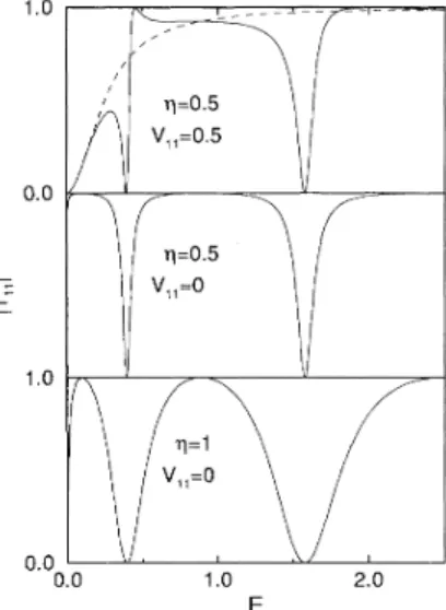
Fig. 6.
Increasing the interaction between the subbands causes the regions of near unity transmissionto
become narrower and the dipsto
become wider, in qualitative agreement with Refs. 12 and13.
Movement
of
the poles and zeros in the complex energy plane is consistent with this behavior. Since our present two-band model isonlya
crude approximationto
the sys-temof
Refs. 12 and13,
we do not intend a quantitative comparison.When we include additional scattering
at
the junc-tion by having Ag
0, we findthat
the interference varies from constructiveto
destructive (asin Figs. 2 and4).
Including intrasubband scattering along the wave-guide (in this approximation) also forces the real part of the poles away fromkI
=
n~.
Thus, in the presence of a barrier near the junction, our results even more closely resemble the onesof
Ref.13,
further strengthening the justification for our two-band model.FIG.
6. Transmission probability versus energy for the electron waveguide coupled to a resonant cavity of length L=
5. The lower two panels show different values of cou-pling strength g. Intrasubband scattering along thewaveg-uide has also been taken into account in the upper panel, where Vjq
=
+iA=
0.5. A clear Fano line shape emerges with sufBcient intrasubband scattering. The dashed curve in the upper panel corresponds to the case when the waveguide and resonant cavity are decoupled (g=
0).
IV.
EFFECT
OF
THE OTHER
SUBBANDS
Real scattering problems cannot be quantitatively de-scribed using only two subbands. The effects
of
other configurations (which correspondto
more than two sub-bands in quasi-1D systems) have been investigated by Fano and Mies, who called them "overlap" effects. Despite the differences with atomic systems, the Fano-resonance line-shape still survives in quasi-1D electronic systems in the presenceof
further intersubband interac-tions.Figure 7 shows the conductance
of
the waveguide for the model ofSec.
II
when multiple subbands are present. Neither(a)
additional propagating subbands,(b)
addi-tional evanescent subbands, or(c)
both qualitatively al-ters the Fano line shape. Further, the Fano line shape is not very sensitiveto
the typeof
intersubband inter-action. In Figs.7(a)
and7(b)
the interaction matrices are tridiagonal, sothat
only adjacent subbands interact, whileFig. 7(c)
allows all the subbandsto
interact.The presence
of
additional subbands can weaken the completely constructive and completely destructive inter-ference present in the two-band model, removing the per-fect unity or zero transmission. Includingextra
evanes-cent subbands also causes a loweringof
the bound-state energy, shown in Figs.7(b)
and7(c).
However, the basic Fano line shapeof
the resonance remains qualitatively unchanged in the presenceof
multiple subbands.Reducing the number
of
"subbands"to
one elimi-nates the Fano resonance.If
all transmitted waves must25S8 ERKAN TEKMAN AND PHILIP
F.
BAGWELL 1.0 ImfE} 0.0 O 0 Gj 1.0 0 I— / / / / / / / / / / / / (b) 0.0 0.60 0.70 0.80 E 0.90 1.00FIG.
7. Conductance versus energy through a multisub-band waveguide. We consider (a) one decaying and fivepropagating subbands, (b) five decaying and one propa-gating subband, and (c) five decaying and five
propagat-ing subbands. The resonances are qualitatively unchanged by the presence of multiple bands. (The subband ener-gies are e
=
(n—
1).
The potential matrix elements areV„„=
—
1 andV,
+j.—
—V,
„q
—
—
0.5. For the lowest panel, the o8'-diagonal potential matrix elements are chosen as V,~=
0.5exp(—
2[~i—
j~—I]).
The dashed curves show theresult for the two-band approximation.
)
pass through a resonant cavity, which is the case in
a
single-channel conductor, one obtains the standard resonant-tunneling transmission probability. The quasi-boundstate
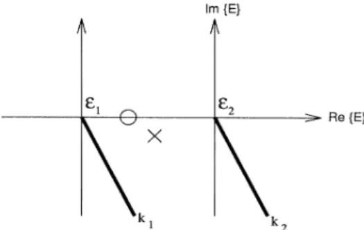
in such a resonant cavity produces the pole (cross) shown in Fig.8.
For the Fano resonance, the elec-tron can either transmit directly through the conductor or pass through some typeof
resonantstate.
The inter-fering amplitudes for the direct and bound-state trans-mission channels give riseto
a transmission zero (cir-cle) shown in Fig.8.
The combination ofthis pole-zero pair produces the asymmetric Fano line shape. Thus, the main feature which difFerentiates the Fano resonance from resonant tunneling is the existence of two inde-pendent transmission channels, only oneof
which passes through the quasiboundstate.
Re{E}
FIG.
8. Pole (cross) and zero (circle) structure of the trans-mission coefBcient Tzz in the complex energy plane. The pole denotes aquasibound energy level, while the zero arises from an interference between direct and intersubband transmission channels. The combined pole-zero pair produces the charac-teristic Pano line shape. The thick lines denote the cut forthe square-root function used to find the wave vector associated with each subband (Ref.19).
a GaAs/A1~Gai 2,As/GaAs heterojunction, and
trans-port in an electron waveguide coupled
to
aresonant cav-ity. Wave interference between the direct and intersub-band transmission in quasi-1D electronic transport pro-duce Fano resonances in the conductance versus Fermi energy orwaveguide width. Wefurther showed the Fano resonances arising in these systemsto
be robustto
the inclusionof
multiple subbands. Fano resonances can also occur in dirty electronic conductors, provided many such conductors are added in parallel. These facts should encourage experimental searches for Fano-type efFects in multisubband electron-transport systems.Besides the three physical systems emphasized in this paper, other systems display the Fano type
of
transmis-sion resonance. In additionto
transmission through an oscillating potential,"
the bound and resonant states as-sociated with the Hall efFect and bend resistanceof
quan-tum wire junctions ~ also appearto
be of the Fanotype. Fano resonances seem
to
appear inlow-dimensional electronic systems whenever acontinuum level associated with one band iscoupledto a
discrete level from asecond band.ACKNOWLEDGMENTS
V.
CONCLUSION
We developed
a
two-band model which adequately de-scribes electronic transport through adonor impurity in an electron waveguide,I'
—
X
—
I'
intervalley tunneling inWe thank Muhammad Alam for pointing out the Fano resonances and for discussions. We gratefully acknowl-edge financial support from the David and Lucile Packard Foundation. One ofus
(E.T.
) is also gratefulto
the Sci-entific and Technical Research Council ofTurkey. * Permanent address: Department ofPhysics, BilkentUni-versity, Bilkent 06533,Ankara, Turkey.
U. Fano, Phys. Rev.
124,
B1866(1961).
A simple discus-sion can be found in Sec. 2.10 of A.P. Thorne, Spectro-physics (Wiley, New Y'ork, 1974).F.
H. Mies, Phys. Rev.175,
164(1968).3. M, Blatt and V.
F,
Weisskopf, Theoretical NuclearPhysics (Wiley, New Y'ork, 1952).See Chap. IX, Fig. 2.2, and Chap. VIII,Figs. 8.2, 5.4,and 5.5.
C.S.Chu and R. S.Sorbello, Phys. Rev.
B
40,5941(1989). P.F.
Bagwell, Phys. Rev.B
41,
10354 (1990);J.
Phys. Condens. Matter 2, 6179(1990).
E.
Tekman and S.Ciraci, Phys. Rev.B
42, 9098(1990). P.F.
Bagwell andR.
K. Lake, Phys. Rev.B
46, 1532948 FANO RESONANCES IN QUASI-ONE-DIMENSIONAL. . . 2559
(5 2) (1992). See also P.
F.
Bagwell, A. Kumar, andR.
K. Lake, Scattering and Quantum Localization of Electronsby Static and Time-Varying Potentials, in Quantum Effect Physics, Electronics, and Applications, edited by
K.
Ismail,T.
Ikoma, and H.I.
Smith (IOP, London, 1992).J.
U. Nockel, Phys. Rev.B
46, 15348 (1992). P.J.
Price (unpublished).K.
Maschke, P.Thomas, andE.
O.Gobel, Phys. Rev.Lett. 67, 2646(1991).
D.
Y.
K. KoandJ.
C.
Inkson, Semicond. Sci.Technol.3,
791(1988);
J.
P.Cuypers and W.van Haeringen,J.
Phys. Condens. Matter 4,2587(1992);T.
B.
Boykin,B.
Pezeshki, andJ.
S.Harris, Phys. Rev.B
46, 12769 (1992); D.Z.Y.
Ting and
T.
C.McGill, ibid 47, 72.81(1993).
F.
Sols, M. Macucci, U. Ravaioli, and K. Hess,J.
Appl. Phys.66,
3892 (1989).W. Porod, Z. Shao, and C. S.Lent, Appl. Phys. Lett,
61,
1350(1992).
H.UBaranger, Phys. Rev.
B
42, 11479 (1990);H. Tamura andT.
Ando, ibid 44, 1.792(1991).
A.Kumar and P.
F.
Bagwell, Phys. Rev.B
44, 1747(1991).
The Schrodinger equation (2.1) does not define unique length and energy units. The only relevant quantity is
h /2m*, which is equal to 57 A eV for GaAs. We take
h /2m* equal to unity in the analysis here. Thus, either the length or energy scale is fixed once the unit of the other is given. In our numerical examples one can take the unit of potential matrix elements to be 1eVA, which yields an energy unit of 18meV and a length unit of
-
57 A.E.
Tekman and S.Ciraci, Phys. Rev.B
40, 8559 (1989);43,
7145(1991).
M. Biittiker, Phys. Rev. Lett.
57,
1761 (1986); R. Lan-dauer,J.
Phys. Condens. Matter1,
8099(1989).
At this point, we must define the square root function we
are using. Since the square root isnot asingle-valued func-tion, it is necessary to have a cut in the complex energy plane. For each subband (1and 2in the two-band model) one has such a cut. The real (imaginary) part of
k„has
to be positive forE
)
e„(E
(
e ) for real energy, in order to get physically acceptable scattering solutions. It is also clear that the imaginary part of the energy at the pole (the quasibound state) must be negative, so that the solutions decay intime. Putting all these considerations together, weconclude that the cut ofthe square-root function has tolie in the fourth quadrant of complex energy plane (i.e., for
Re(E)
)
0 andIm(E)
(0),
as shown in Fig. 8. Clearly, the exact position of the cut has to be chosen sothat the pole lies in between the two cuts, The more conventional cuts along the negative or positive real axis are not accept-able since the former sweeps away the poles completely, and the latter (aswell as the former) does not comply with the requirement that the conductivity isacontinuous function ofcomplex energy near the real axis.Equations (2.6)—(2.8) can also beexpressed in terms ofthe electron energy. The transmission zero occurs at an energy
E
=
e2—
Ez,
where the binding energyE~
is4EIs
=
(V2z) (5.1)Unity transmission is obtained at
E =
e2—Ez,
with Iv,il' —
v,
Equation (2.8) cannot be solved analytically to determine
the complex energy pole. However, provided the bound state isnot too near asubband edge, and that the binding energy is weak compared to the subband separation, this pole occurs at the energy
E
e2—
E~
+i
EI,
with4&1—— (2ViiV22
—
IV2il)
.2
(5.3)
Y.
B.
Levinson, M.I.
I
ubin, andE.
V.Sukhorukov, Phys Rev.B 45, 11936
(1992).Ch. Kunze and
R.
Lenk, Solid State Commun. 84, 457 (1992).sS.Gasiorowicz, Quantum
Physics (Wiley, New York, 1974), p. 93.
J.
E, Avron, A. Raveh, andB.
Zur, Rev. Mod. Phys.60,
873(1988).
The introduction of the parameter g is an approximation to the problem studied in Ref. 13.Consider the resonant cavity attached to afinite potential barrier, and in the ab-sence ofany interaction between the cavity and waveguide. A hard wall terminates the cavity at y
=
0, with afi-nite potential barrier at y
=
1.
The cavity wave function for 0(
y(
L is then @s«b=
Asin(ky), with a loga-rithmic derivative 9'gs«b/gs«b=
kcot(kL) at y=
I.
This wave function will be matched to an exponentially decaying one in the barrier, giving rise to gs«b(y) Asin(kL)e
""
and 7'i/isa b(y)=
rA is(n—kL)e""
for L &y & oo, K being the inverse decay length in the bar-rier. The logarithmic derivative is therefore unchanged, so that T@s«b/gs«b=
—
K=
kcot(kL) for L(
y(
oo. When interaction between the cavity and the waveguide is turned on, i.e., the finite potential barrier composing oneend of the cavity is lowered to form aportion of the wave-guide, the wave function will have exponentially growing components in addition to exponentially decaying ones. The wave function for
L
(
y(
(L+
d), where d is the thickness of the barrier, will become proportional to (1+
ne"")e
"".
The derivative of the wave function is then proportional to—
K(l—
ne"")e
"".
Here n is asmall number, of the order ofe"",
which must be determined by the exact matching conditions for the problem. Instead of the complete solution (Ref. 13) for these new match-ing conditions, we develop approximate matching condi-tions (3.5)and (3.6). It
is then possible tofocus on the ef-fects of the interaction, using a single parameter g, rather than the detailed mechanism of the interaction. From the previous paragraph, the result of interaction is to increase (decrease) the wave function (derivative) compared to the noninteracting case. Forsmall values of ne"",
which holds when the magnitude of the wave function inside the cav-ity is large (i.e., close to resonance), we may approximatethe factor multiplying the wave function [see Eq.
(3.
5)] as (I/rt) and the one multiplying the derivative [see Eq. (3.6)] as rl. Hence(1+
o.e"")
1/ri and (1—
ne"
) The logarithmic derivative forthe interacting case becomesil kcot(kL), which isEq. (3.7).
The intersubband interaction used in the present approach is not completely realistic, since g has to be a function of A: as noted above. In addition, we can use the present
model only for rI & 1in conjunction with the approxima-tion described above. Although the continuation for g