https://doi.org/10.1007/s10854-020-02906-w
Graphene oxide-doped PEDOT:PSS as hole transport layer in inverted
bulk heterojunction solar cell
Sefika Ozcan1,2 · Mert Can Erer3 · Sesha Vempati4 · Tamer Uyar2,5 · Levent Toppare1,3,6,7 · Ali Çırpan1,3,6,7
Received: 3 August 2019 / Accepted: 13 January 2020 / Published online: 25 January 2020 © Springer Science+Business Media, LLC, part of Springer Nature 2020
Abstract
Transparent poly (3,4-ethylenedioxythiophene): poly (styrenesulfonate) (PEDOT:PSS) is widely used hole conducting mate-rial in optoelectronic devices. Secondary doping of PEDOT:PSS enables the tunability of its electronic properties. In this work, graphene oxide (GO) was used as a secondary dopant for PEDOT:PSS and the doped materials (composites) were tested for their efficiency as hole transport material in inverted bulk heterojunction (BHJ) solar cell. The composites were studied to unveil the effects of Coulombic interaction between GO and PEDOT:PSS where we note some segregation of PEDOT phase. We found that the GO majorly interacts with PSS through oxygeneous functional groups which promote the detach-ment of PEDOT from PSS and segregation of PEDOT. Electrochemical properties with and without illumination revealed some photo-induced changes to surface of the samples. Device performances showed about 2.2% efficiency enhancement when GO doping level was 0.25 (v:v) when compared to that of pristine PEDOT:PSS.
1 Introduction
Bulk heterojunction organic solar cells have been at the center of remarkable research and development, owing to their relatively lower cost, light weight, flexibility and in addition, tunable electronic properties [1]. Notably, most of these properties are indeed open to improvements. The improvements could be achieved through novel molecu-lar designs, and controlling the optoelectronic properties by means of doping etc. [2, 3]. In the conventional bulk
heterojunction (BHJ) solar cell the active layer can be a composite of donors and acceptors [4]. This active layer is sandwiched between indium tin oxide (ITO) and another low work function metal to form BHJ. It was found that the metal contacts are rather vulnerable to degradation [5]. Consequently, inverted BHJ solar cells were introduced to eliminate the need of low work function and air-sensitive metal contacts. The inverted structure has depicted extended stability which uses a transparent metal oxide as the electron transport layer (ETL) such as ZnO, TiO2 on ITO while a top metal contact (Ag, Au etc) is deposited on the active layer [6, 7]. In fact, the direct deposition of top metal contact may lead to the diffusion of the metal through the active layer manipulating its electronic properties [8]. Inevitably,
Electronic supplementary material The online version of this article (https ://doi.org/10.1007/s1085 4-020-02906 -w) contains supplementary material, which is available to authorized users. * Sesha Vempati [email protected] * Ali Çırpan [email protected] Tamer Uyar [email protected] Levent Toppare [email protected]
1 Department of Polymer Science and Technology, Middle
East Technical University, 06800 Ankara, Turkey
2 UNAM-Institute of Materials Science & Nanotechnology,
Bilkent University, 06800 Ankara, Turkey
3 Department of Chemistry, Middle East Technical University,
06800 Ankara, Turkey
4 Department of Physics, Indian Institute of Technology Bhilai,
Raipur 492015, India
5 Department of Fiber Science and Apparel Design, College
of Human Ecology, Cornell University, Ithaca, NY 14853, USA
6 Department of Micro and Nanotechnology, Middle East
Technical University, 06800 Ankara, Turkey
7 The Center for Solar Energy Research and Application
(GÜNAM), Middle East Technical University, 06800 Ankara, Turkey
there exists an energy barrier between metal contact and active layer which, however, can be reduced by matching the work function of the metal with the LUMO of the acceptor and HOMO of the donor of the active layer materials [9, 10]. In this context, hole transport layer (HTL) has been employed in between active layer and metal contact which improves the device performance in terms of charge trans-port. If we look at the functionality of solar cells based on organic semiconductors, a photon of suitable energy when absorbed creates a bound electron-hole pair (exciton) which is in contrast to the inorganic semiconductors where exciton formation may occur at a later stage. When the exciton dis-sociates, the charge carriers may move towards their respec-tive electrodes contributing to the photocurrent. Thus, in the case of inverted structure, modifying the properties of HTL between active layer and metal contact is a promis-ing method to improve device performance [11]. In fact, PEDOT:PSS is a commonly used material as HTL in vari-ous devices [12–15], owing to its high work function, easy solution processability, high conductivity and high opti-cal transmittance in the visible spectral region [16]. PSS moieties dope PEDOT units through ionic bonds and sta-bilize them in aqueous media [17]. Although excess PSS is known to enhance the dispersion stability, its insulating nature reduces the overall conductivity. However, the con-ductivity can be enhanced through ‘secondary doping’. The secondary doping helps in phase separation and thus the for-mation of large PEDOT domains. The dopants such as metal oxides [18], solvents [19, 20], solid electrolytes [21], ionic liquids [22], surfactants [23] etc are employed as secondary dopants. Apart from these recently graphene oxide (GO) has been employed as a secondary dopant in PEDOT:PSS. The photovoltaic performance of GO/PEDOT:PSS com-posite is improved due to the increase in the conductivity of the composite. Well-matched work function between the GO/PEDOT:PSS and ITO is also a notable factor, where the former depicts better electron blocking property due to the bandgap of GO. Moreover, in the presence of GO,
relatively stable and efficient device structures can be achieved [24–29]. GO/PEDOT:PSS composite is found to be promising and employed in perovskite [28], silicon- organic hybrid solar cell [29] as well as in conventional BHJ solar cell [30–32].
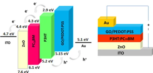
Here, in this work, we have employed GO in PEDOT:PSS to enhance the optoelectronic properties of PEDOT:PSS and used as HTL for P3HT:PC71BM-based BHJ solar cells (see
Fig. 1). We have also performed a comparative study with pristine PEDOT:PSS, where power conversion efficiency (PCE) of 2.71% is achieved for GO/PEDOT:PSS of 0.25 v/v corresponding to ~ 5% increase. This enhancement in the optoelectronic properties is supported by Raman and X-ray photoelectron spectroscopy analyses. Moreover, we have identified the interaction between the GO and PEDOT:PSS, where the conducting PEDOT phase is separated from the insulating PSS domains. This phase separation enhanced the electronic properties leading to improved device properties.
2 Materials and methods
2.1 Preparation and characterization of GO/ PEDOT:PSS films
GO was synthesized as described in an earlier work [33, 34]. Aqueous dispersion of GO was prepared with a GO/ H2O ratio of 0.5 mg/mL by 30 min sonication. PEDOT:PSS (Clevious HTL solar) was purchased from Heraeus Ltd. and filtered through 0.45 µm CA syringe filter. GO-disper-sion was added dropwise to the known volume of filtered PEDOT:PSS until GO/PEDOT:PSS v/v ratio is 0.15, 0.2 or 0.25. These dispersions were stirred for 30 min at room tem-perature. We have employed spin casting to deposit films. These spin-casted films were dried on hot plate at ~ 110 °C for 10 min.
Fig. 1 Schematic of the bulk heterojunction solar cell.
Zinc acetate dihydrate (Zn(AC)2), ethanoldiamine, 2-methoxy ethanol were purchased from Sigma-Aldrich. Zn(AC)2 dispersion was prepared in ethylenediamine and
2-methoxyethanol with a concentration of 0.36 mM to be used as the ETL layer.
Surface chemical properties were investigated with X-ray photoelectron spectroscopy (XPS) Thermoscientific K-Alpha, Al Kα radiation (hν = 1486.6 eV) in the presence of a flood gun charge neutralizer. The spot size of the X-ray source was 400 µm in diameter. To record the core-level XP spectra, the pass energy and step size were set to 30 eV and 0.1 eV, respectively. Spectral deconvolutions of the XP data were performed through Avantage software (with Shirley background). The intensity difference in XP spectra was obtained after subtracting Shirley background followed by normalization to the maximum intensity. UV–Vis spectros-copy was performed with Cary BiO 100 UV –Vis spectro-photometer from spin-casted films on quartz substrate. X-ray diffraction (XRD) patterns (2θ = 13°–31°) of PEDOT:PSS films were recorded with PANalytical X’Pert Multi Purpose X-ray Diffractometer (CuKα = 1.5418 Å). Raman spectros-copy was performed on film samples with WITec instru-ments (Alpha 300S, 532 nm laser). Origin 8.5 was employed for the analyses of Raman spectra. Electrochemical measure-ments were conducted at room temperature with CH instru-ment 600E series work station at 100 mV/s ramp rate. Stand-ard three electrode cell was used, where PEDOT:PSS or GO/ PEDOT:PSS coated ITO was used as the working electrode while, platinum wire and Ag│AgCl│KCl(saturated) were served as counter and reference electrodes, respectively. Single-scan cyclic voltammetry (CV) measurements were performed in 0.1 M NaCl(aq). The scan rate was kept at 100 mV/s for each measurement. Prior to the measurement, the electrolyte solution is saturated with Ar gas for 30 min. Each sample measured under dark and light sequentially. A solar simulator (air mass (AM) 1.5G, 100 mW/cm2) was used for
illuminating the sample during CV measurements when the samples were kept at 25 °C.
2.2 Device fabrication
Inverted bulk heterojunction solar cells with ITO/ZnO/ P3HT:PC71BM/(GO/PEDOT:PSS)/Au architecture (Fig. 1)
were constructed for IV measurement. For this purpose, ZnO dispersion was spincoated onto clean ITO substrates at 4000 rpm for 40 s, in ambient atmosphere. Thereafter, coated sub-strates were baked at 150 °C for 25 min.
Poly(3-hexylthiophene-2,5-diyl) (P3HT) and [6, 6]-Phe-nyl-C71-butyric acid methyl ester (PC71BM ) solutions were prepared with a weight ratio of P3HT:PCBM 1:0.8, and P3HT concentration of 20 mg/mL, in o-dichloroben-zene. The prepared solutions were filtered through a pol-ytetrafluoroethylene filters with 0.45 µm pore size. Filtered
solutions were spincoated onto the ZnO/ITO substrates at 750 rpm, in a glovebox. Both PEDOT:PSS and GO-doped PEDOT:PSS dispersions with different doping concentra-tions were coated onto the active layer, in ambient atmos-phere. These substrates were annealed at 110 °C for 10 min followed by a deposition of Au (~ 80 nm at 1 × 10− 6 mbar of
reduced pressure) cathode layer. The devices were charac-terized under illumination of AM 1.5G, with Keithley 2400 setup. The final device structure is as shown in Fig. 1.
3 Results and discussion
The tunable optoelectronic properties and dispersivity in H2O make GO a good candidate to dope PEDOT:PSS. We
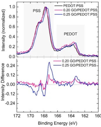
have earlier shown that GO is functionalized with oxygen-containing groups such as COC, COH, COOH, and COOR of different densities [34]. GO can interact with PEDOT:PSS either via its functional groups and/or through π–π inter-action [35]. To investigate the surface chemical properties and composition, XPS studies were performed. Figure 2a and b show the normalized XP spectra of pristine/doped samples, and the change in intensity of S2p spectra with respect to that of PEDOT:PSS, respectively. The peaks in the range of 162–166 eV belong to S atoms on EDOT0 while in
Fig. 2 a S2p core-level spectra of PEDOT:PSS films with and
with-out GO doping and b spectral intensity difference with respect to that of PEDOT:PSS.
the range of 166–171 eV originate from that of PSS− (such
as H+PSS−, Na+PSS− or EDOT+PSS−) [36, 37]. From the
spectra it was observed that in the presence of GO, the PEDOT contribution to the composite films was increased. In other words, the fraction of PSS at the surface of the films has decreased after GO doping. Accumulation of PSS at the surface of PEDOT:PSS films is inevitable due to the Coulombic effects [21, 38, 39].
By given the chemical structure of GO, it would inter-act with PSS as well as PEDOT through the oxygen (–O–) and hydroxyl (–OH) functional groups. Consequently, new hydrogen bonds and/or dipole-dipole or dipole-charge inter-action with PEDOT as well as PSS are expected [40]. When GO is added to aqueous PEDOT:PSS dispersion negatively charged PSS is likely to dissolve in water by establishing Coulombic-type interaction with GO. This weakens the Coulombic interaction of PSS with PEDOT. At this stage, PEDOT chains tend to form linear conformation as the screening from negatively charged PSS is reduced. In addi-tion, π–π interaction is expected between PEDOT and GO or the hydrophilic functional group on GO. The aforemen-tioned interactions between polymeric units and GO lead to the formation of conductive pathways [13]. Notably, GO-PSS interaction promotes the detachment of GO-PSS units while GO-PEDOT interaction results in charge-collection paths improving the conductivity and electronic properties. Such interactions, however, may be reflected in the core-level spectra explicitly. Indeed a shift to lower-binding energy side was observed upon GO doping [13, 41]. Red shift in the spectral feature is expected when the surface becomes rela-tively electron rich. In other words, if a material is subjected to reduction or gains some electron density, then the binding energy per electron from nucleus decreases which results in a red shift. Essentially, we conclude that the interaction of GO with PEDOT:PSS resulted in an electron-rich mate-rial than PEDOT:PSS. On the other hand, the apparent red shift of the spectra upon GO doping can also be understood from the differences in the intensities of the unconvoluted peaks. As total S contribution from PEDOT (between 167 and 168 eV) increased while that of from PSS (between 169 and 170 eV) decreased (see Fig. 2b), it is more convinc-ing to attribute the peak at 167–168 eV to EDOT+:SS− and
169–170 eV to H+PSS− [20], where EDOT and SS stand for
the monomers of PEDOT and PSS, respectively. In this case, the spectral differences indicate that H+SS− contribution is
decreased as it detached from the PEDOT:PSS unit upon the interaction with GO. EDOT+:SS− increment is due to
electron deficiency in EDOT backbone. On the other hand, an increased contribution of EDOT0 in Raman spectra is
observed, and will be discussed later. We conclude that there are competing oxidation and reduction processes between GO and PEDOT and PSS occurring simultaneously.
GO being a secondary dopant, the GO/PEDOT interac-tion may result in phase segregainterac-tion and hence removal of a fraction of the primary dopant, PSS. Removal of insulat-ing PSS units from PEDOT-backbone is possible, when the charge on PSS is compensated by Coulombic interaction from GO and/or other counter ions. The separation of PSS would also be in the form of PSS–H or PSS–Na which can take place upon interaction with the hydrophilic units on GO. This, in return, leads to an increase in the conductivity of the composite [41]. Furthermore, the intrinsic ity of GO might have its contribution to the total conductiv-ity, and it is not trivial to disentangle from that of the com-posite and even pristine PEDOT:PSS, as discussed in the following. The electronegativity of the oxygen-containing functional groups withdraws some fractional density of elec-trons from the basal plane and also creates scattering cent-ers for the charge carricent-ers. These influence the conductivity when the graphene is oxidized (i.e. GO). Now, in the pres-ence of PEDOT:PSS the fractional shift of charge from the basal plane of graphene to oxygeneous functional groups is different when compared to plain GO [34]. Hence, unfolding the contributions of the conductivity of each of the compo-nent to the total is not trivial.
Now, we would like to unveil the effect of the interaction between GO and PEDOT:PSS on the changes to the absorb-ance of optical transitions from occupied states. Figure 3 represents a set of typical UV-visible absorption spectra of composite films. Absorption spectra until 1.7 eV is shown in Figure S1. The peak in the range of 5.8–5.2 eV is character-istic to aromatic rings of PSS unit. As it is clear in Fig. 3, the decrease in the intensities of the absorption band of benzene ring from PSS in UV range of 5.8–5.2 eV confirms the par-tial removal of PSS units upon GO doping in PEDOT:PSS.
Fig. 3 UV-Vis absorption spectra of PEDOT:PSS film with and
Almost no significant change is observed in visible range after GO doping (Figure S1). Due to the interaction between GO and PSS, GO induces separation of PSS from PEDOT moieties without severely affecting visible range absorption property of the composite. The results are consistent with the literature [42].
XRD patterns from pristine PEDOT:PSS and composite films depicted some amorphous peak-like structures (see Fig. 4). Evidently, two features are observed for all films which are located at ~ 17.6° and ~ 26° of angular posi-tions. The peak centered at ~ 17.6° corresponds to PSS unit whereas peak centered at ~ 26° corresponds to interchain planar ring stacking distance of PEDOT [43, 44]. On the normalized intensity scale, we observed a nominal sup-pression of PSS-related peak (~ 17.6°) for both composites. This may be an evidence of relatively stronger interaction with PSS units and hydrophilic functional groups of GO, which might result in a phase separation of PEDOT and PSS. For 0.2 GO/PEDOT:PSS composite, suppression of PEDOT-related peak (~ 26°) was also observed. Essentially, we note some decreased long-range order. As a result of the interaction, both PEDOT and PSS conformation may be distorted. On the other hand for the case of 0.25 GO/ PEDOT:PSS, apart from subdued intensity of PSS-related peak, an increase in intensity of PEDOT-related peak (~ 26°) and shift to higher 2θ values are observed. This means both PSS separation and alignment of PEDOT chains take place as GO doping reaches 0.25 v:v [35].
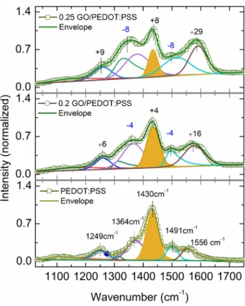
To further understand the interaction between GO and PEDOT:PSS, Raman microscopy analyses were conducted and the spectra along with fits are depicted in Fig. 5. The characteristic peak of PEDOT:PSS occurred at 1429 cm−1
corresponding to C=C stretching which is sensitive to π
electron density/delocalization. With increasing GO dop-ing, the area under this peak is decreased and blue shifted to 1434 cm−1. This is attributed to π–π interaction of GO
basal plane with PEDOT aromatic units [45]. Various other bands from PEDOT:PSS are asymmetric C=C stretching (1560–1650 cm−1), C–C inter-ring stretching (1249 cm−1)
and single C–C bond stretching (1364 cm−1) [29, 46]. As
GO-doping level increases, the band at 1249 cm−1 shifted
to higher wave number of 1260 cm−1. This blue shift, in the
presence of GO-doping level can be attributed to the forma-tion of neutral PEDOT (EDOT0). Furthermore, PSS-related
bands at 982 cm−1 and 1114 cm−1 were shown in Fig S2
[47]. The intensity of bands at 982 cm−1 and 1114 cm−1
were decreased as GO amount increased. These observations suggest the detachment of PSS from PEDOT in the pres-ence of GO, which is consistent with our XPS and UV–Vis measurements.
The characteristic response from GO appears within 1360–1375 cm−1 and 1590–1650 cm−1 corresponding to D
and G bands, respectively. D band is related to defects or dis-order in sp2 hybridized carbon systems. The primary mode,
G band is due to the planar configuration of sp2-bonded
carbon/basal plane. G band from GO and asymmetric C=C
Fig. 4 XRD patterns of PEDOT:PSS films compared with that of GO-doped films.
Fig. 5 Raman spectral response of PEDOT:PSS film with and with-out GO doping. Peak shifts with reference to the spectral positions peaks from PEDOT:PSS are shown in the units of cm−1 where –ve
and +ve signs indicate red and blue shifts, respectively (Color figure online).
stretching from PEDOT:PSS were observed in the range of 1560–1650 cm−1. Shifts associated in this region could
be ascribed to relatively stronger interaction of sp2 of GO
with conjugated moieties in PEDOT:PSS. We concluded that both GO basal plane and functional group interact with PEDOT:PSS separately. Notably, Rafique et al. [32] did not observe any interaction between GO and PEDOT:PSS in their double-decked structure. This may be due to the fact that the interaction is limited to the interface of GO and PEDOT:PSS. In clear contrast, in our case, we have fabri-cated a composite structure where the interaction is maxi-mized and could be probed with non-interface-sensitive techniques.
In the case of GO/PEDOT:PSS system, we expect that the density of polaron and bipolaron species in PEDOT:PSS change [21]. By given the nature of interaction between GO and PEDOT:PSS [21, 48], we also speculate that the effect of doping may be limited to the highest occupied molecular
orbital (HOMO) edge or close to the Fermi energy. Essen-tially, O2p and mixed state of O2p/C2p of PEDOT are effected that may play a direct role in the transport properties and hence the device efficiency. On the other hand, slightly deeper states such as C2s and O2s may also be affected. However, we emphasize that the changes to the electronic structure and polaronic states need further spectroscopic support.
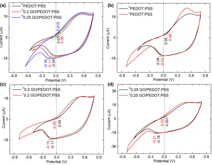
By given the functionality of the solar cell, electrochemi-cal properties of the pristine and GO/PEDOT:PSS films were characterized by cyclic voltammetry (CV) under dark and illuminated conditions. To start with, CV curves obtained under dark conditions for each sample are compared in Fig. 6a showing the effect of GO doping on electrochemical properties of PEDOT:PSS. As indicated in Fig. 6a, a pair of broad redox current peaks are observed, where the ‘broad-ness’ can be attributed to relatively low electroactivity of the films. The electroactivity is dependent on the chemical
Fig. 6 Single-scan CV curve of a PEDOT:PSS with and without GO doping in dark, b PEDOT:PSS in the presence of illumination compared with dark c and d 0.2 and 0.25 v:v of GO/PEDOT:PSS under dark and light conditions, respectively.
nature of the surface. The kinetics of the reduction and oxi-dation are different as evidenced by the differences in the profile of the peaks.
When PEDOT:PSS gains electrons, it loses positive charge and becomes relatively insulating. That is to say that PEDOT is reduced to undoped form. The converse is true for the case of oxidation. In the case of composites, the electrochemical activity is a result of all active components of PEDOT:PSS as well as GO, which however, could not be distinguished. As the doping increases the position of reduction peak did not change significantly, while a small, however, notable shift is noted towards higher potential. The positions are annotated in Fig. 6c and d. The shift of cathodic potentials means that GO-doped PEDOT:PSS has lesser tendency to get reduced, or the energy barrier to remove the electron is higher from the surface of the films. Essentially, the material gets charged at the same potential, however, now it discharges at a higher potential. Hence the GO/PEDOT:PSS composites are more stable and less likely to lose their positive charge and hence maintain their con-ductivity in wider potential range.
The functionality of the BHJ solar cell needs to be under-stood when subjected to illumination. In connection to this, CV measurements were performed in the presence of a simi-lar illumination to record the changes in the electrochemical behavior of pure and doped PEDOT:PSS films. Figure 6b shows data after one dark scan, under the potential window 0.8 V to until about − 0.5 or − 0.8 V at 100 mV/s ramp rate. i.e. first scan is performed in dark, while the second scan under illumination. We would like to point-out that the second CV cycle on PEDOT:PSS has depicted some changes to the profile indicating the altercations to the elec-trochemical nature at the surface, (see Figure S3). Hence the changes to the CV curves contain contributions from the altered electrochemical nature and photogenerated charge. For PEDOT:PSS sample, under illumination, there is an increase in the oxidation current without any shift of redox peak potentials. The increased current could be associated with the capacitive behavior of the films. On the other hand, under illumination (See Fig. 6b), the potential range of all samples has significantly increased while onsets of redox potentials are nominally unchanged. It is notable that elec-trochemical studies under illumination were not discussed in the earlier studies [13, 24–28, 32, 41] which employed com-binations of GO and PEDOT:PSS as HTL layer. We believe that this characterization provides a better understanding of electron transfer mechanism and charge transfer affinity of the blend as the fractional quantity of GO is increased.
J–V curves of the P3HT:PC71BM based inverted BHJ solar cells in which pure and GO-doped PEDOT:PSS dis-persions were used as HTLs are given in Fig. 7. The pho-tovoltaic characteristics are averaged over 5 devices and summarized in Table 1. Power conversion efficiency values
calculated for the best performing devices are tabulated in brackets. The overall efficiency of the devices were enhanced from 2.69 to 2.75%, and the enhancement towards the addi-tion of GO to the PEDOT:PSS was confirmed by consider-ing the cell to cell variation for 5 devices of each blend. HTL of 0.25 GO/PEDOT:PSS showed superior performance with a power conversion efficiency of 2.75%, short circuit cur-rent (Jsc) of 7.75 mA/cm2 and an open circuit voltage (VOC)
of 0.58 V. Increase in PCE for 0.25 GO/PEDOT:PSS layer compared to the pristine counterpart is mainly through an increase in photocurrent, from 7.51 to 7.75 mA/cm2.
Com-paring, 0.20 GO/PEDOT:PSS and 0.25 GO/PEDOT:PSS samples, the JSC values differ slightly. However, 0.25 GO/
PEDOT:PSS showed relatively lower fill factor (FF%) across all other concentrations. Lower FF can be originated from relatively inhomogeneous morphology of the composite, however, higher Jsc is notable which does not compromise
the device efficiency. Higher Jsc from 0.25 GO/PEDOT:PSS device can be attributed to the formation of aligned PEDOT chains which provide efficient carrier delocalization, better charge transport and increases the conductivity.
The efficiency of our devices is relatively lower, when compared to a study by Rafique et al. [32]. The reasons for the lower efficiency are discussed in the following. Instead of building a double-decked structure as in Reference [32], we have fabricated a composite structure. On the other hand,
Table 1 Summary of the photovoltaic performances of devices for P3HT:PC71BM ratio of 1:0.8. GO/ PEDOT:PSS Jsc (mA/cm 2) V oc (V) FF (%) ɳ (%) 0 7.51 0.58 61.8 2.69 (2.69) 0.20 7.59 0.58 62.5 2.75 (2.77) 0.25 7.75 0.58 61.2 2.75 (2.75)
Fig. 7 J–V curves of the P3HT:PC71BM based inverted BHJ solar cells with and without GO doping.
the properties of PEDOT:PSS are not identical. For instance, we have observed the presence of PSS, in Reference [32] there is no such indication. PSS being insulating in nature, it not only reduces the overall conductivity, but also influ-ences the conduction mechanism. While the differinflu-ences in the viscosity of PEDOT:PSS solutions would influence the formation of the film and hence the nature and efficiency of electron transport. Also, the mode of synthesis [32, 33] of GO greatly modifies the functional groups and their density at the surface of graphene [21, 34]. This in turn changes the degree of doping of PEDOT:PSS, however, the nature of fundamental interaction still remains as we discussed in the previous sections.
4 Conclusions
The tunable properties of PEDOT:PSS are rather moti-vating where we have employed a potential material, graphene oxide as a secondary dopant to develop a novel HTL. We have fabricated a composite where the interac-tion between GO and PEDOT:PSS is maximized and could be probed with non-interface sensitive techniques. Within the resolution limits, scanning electron microscopy images (Figure S4) revealed that the GO is dispersed uniformly within PEDOT:PSS. As evidenced from the XPS results, the interaction between GO and PEDOT, removed a frac-tion of the primary dopant, PSS via charge compensafrac-tion. Consequently, the composite is expected to depict higher electrical conductivity. As a result of interaction, the opti-cal absorption spectra indicated the separation of PSS units from PEDOT without affecting visible range trans-mission. XRD patterns from GO-doped samples suggested decreased long-range order and possible distortion of the conformation of PEDOT and PSS chains. Raman spectros-copy gave a strong indication that the basal plane of GO and its functional group interact with PEDOT as well as PSS units separately. We conclude that the PEDOT:PSS upon doping with GO depicted superior electronic proper-ties. In the context of electrochemical response (dark and illuminated conditions), it is found that the presence of GO increases the discharge potential window of PEDOT:PSS. When GO-doped in PEDOT:PSS for inverted BHJ solar cell, we found enhancement in efficiency about 2.2% for 0.25 GO/PEDOT:PSS sample. Given the improvement of efficiency of BHJ solar cell, we believe that this study will contribute to the further development of lower cost and flexible hole transport layers.
References
1. J. Peet, A.J. Heeger, G.C. Bazan, Acc. Chem. Res. 42, 1700 (2009)
2. Y. Li, Acc. Chem. Res. 45, 723 (2012)
3. F.C. Krebs, N. Espinosa, M. Hösel, R.R. Søndergaard, M. Jør-gensen, Adv. Mater. 26, 29 (2014)
4. H. Hoppe, N.S. Sariciftci, J. Mater. Res. 19, 1924 (2004) 5. P. Cheng, X. Zhan, Chem. Soc. Rev. 45, 2544 (2016)
6. S.K. Hau, H.-L. Yip, N.S. Baek, J. Zou, K. O’Malley, A.K.Y. Jen, Appl. Phys. Lett. 92, 225 (2008)
7. M.-S. White, D. Olson, S. Shaheen, N. Kopidakis, D.S. Ginley, Appl. Phys. Lett. 89, 143517 (2006)
8. J. Birgerson, M. Fahlman, P. Bröms, W.R. Salaneck, Synth. Met.
80, 125 (1996)
9. L. Lu, T. Xu, I.H. Jung, J. Phys. Chem. C 118, 22834 (2014) 10. H. Ma, H.L. Yip, F. Huang, A.K.Y. Jen, Adv. Funct. Mater. 20,
1371 (2010)
11. H.-L. Yip, A.K.Y. Jen, Energy Environ. Sci. 5, 5994 (2012) 12. A. Elschner, F. Bruder, H.-W. Heuer et al., Synth. Met. 111, 139
(2000)
13. X. Wu, J. Liu, D. Wu et al., J. Mater. Chem. C 2, 4044 (2014) 14. A. Arias, M. Granström, K. Petritsch, R.H. Friend, Synth. Met.
102, 953 (1999)
15. A. Arias, M. Granström, D. Thomas, K. Petritsch, R.H. Friend, Phys. Rev. B 60, 1854 (1999)
16. E. Vitoratos, S. Sakkopoulos, E. Dalas et al., Org. Electron. 10, 61 (2009)
17. L. Groenendaal, F. Jonas, D. Freitag, H. Pielarzitzik, J.R. Reyn-olds, Adv. Mater. 12, 481 (2000)
18. A. Kanwat, W. Milne, Sol. Energy Mater. Sol. Cells 132, 623 (2015)
19. J. Ouyang, C.W. Chu, F.C. Chen, Q. Xu, Y. Yang, Adv. Funct. Mater. 15, 203 (2005)
20. X. Crispin, F. Jakobsson, A. Crispin et al., Chem. Mater. 18, 4354 (2006)
21. S. Vempati, Y. Ertas, A. Celebioglu, T. Uyar, Appl. Surf. Sci. 419, 770 (2017)
22. C. Badre, L. Marquant, A.M. Alsayed, L.A. Hough, Adv. Funct. Mater. 22, 2723 (2012)
23. F.J. Lim, K. Ananthanarayanan, J. Luther, G.W. Ho, J. Mater. Chem. 22, 25057 (2012)
24. H.S. Dehsari, E.K. Shalamzari, J.N. Gavgani, F.A. Taromi, S. Ghanbary, RSC Adv. 4, 55067 (2014)
25. J.C. Yu, J.I. Jang, B.R. Lee, G.-W. Lee, J.T. Han, M.H. Song, ACS Appl. Mater. Interfaces 6, 2067 (2014)
26. D.-Y. Lee, S.-I. Na, S.-S. Kim, Nanoscale 8, 1513 (2016) 27. Y. Park, K. Soon Choi, S. Young Kim, Physica Status Solidi (a)
209(7), 1363 (2012)
28. J. Niu, D. Yang, X. Ren et al., Org. Electron. 48, 165 (2017) 29. X. Jiang, Z. Wang, W. Han et al., Appl. Surf. Sci. 407, 398 (2017) 30. M. Hilal, J.I. Han, Sol. Energy 167, 24 (2018)
31. A. Iwan, F. Caballero-Briones, M. Filapek et al., Sol. Energy 146, 230 (2017)
32. S. Rafique, S.M. Abdullah, M.M. Shahid, M.O. Ansari, K. Sulaiman, Sci. Rep. 7, 39555 (2017)
33. D.C. Marcano, D.V. Kosynkin, J.M. Berlin et al., ACS Nano 4, 4806 (2010)
34. S. Ozcan, S. Vempati, A. Çırpan, T. Uyar, Phys. Chem. Chem. Phys. 20, 7559 (2018)
35. F.-P. Du, N.-N. Cao, Y.-F. Zhang et al., Sci. Rep. 8, 6441 (2018) 36. G. Greczynski, T. Kugler, W.R. Salaneck, Thin Solid Films 354,
129 (1999)
37. U. Voigt, W. Jaeger, G.H. Findenegg, R.V. Klitzing, J. Phys. Chem. B 107, 5273 (2003)
38. S.-J. Wang, H.-H. Park, Thin Solid Films 518, 7185 (2010) 39. M. Campoy-Quiles, T. Ferenczi, T. Agostinelli et al., Nat. Mater.
7, 158 (2008)
41. P.G. Raj, V.S. Rani, A. Kanwat, J. Jang, Mater. Res. Bull. 74, 346 (2016)
42. C. Yeon, G. Kim, J.W. Lim, S. Yun, RSC Adv. 7, 5888 (2017) 43. C.M. Palumbiny, F. Liu, T.P. Russell, A. Hexemer, C. Wang, P.
Müller-Buschbaum, Adv. Mater. 27, 3391 (2015)
44. H. Lee, Y. Kim, H. Cho, J.-G. Lee, J.H. Kim, RSC Adv. 9, 17318 (2019)
45. G. Greczynski, T. Kugler, M. Keil, W. Osikowicz, M. Fahlman, W.R. Salaneck, J. Electron Spectrosc. Relat. Phenom. 121, 1 (2001)
46. S. Garreau, G. Louarn, J.P. Buisson, G. Froyer, S. Lefrant, Mac-romolecules 32, 6807 (1999)
47. M. Stavytska-Barba, A.M. Kelley, J. Phys. Chem. C 114, 6822 (2010)
48. S. Vempati, A. Celebioglu, T. Uyar, J. Mater. Chem. C 2, 8585 (2014)
Publisher’s Note Springer Nature remains neutral with regard to jurisdictional claims in published maps and institutional affiliations.