Journal of İstanbul Kültür University 2002/1. pp. 1-4.
ACoefficientInequality
for Convex Functions
Yaşar Polatoğlu *
*Department of Mathematics Istanbul KültürUniversity34510 Şirinevler Istanbul
Abstract
In this study an important result ofthe papercalled’ A characterization for convex functions ofcomplex order’(Ist. Üniv. Fen Fak. Matematik Dergisi cilt 54 sayfa 175- 179, 1997)is given andwe present acoefficient inequality forconvex functions underthe regularly univalentconditions.
Özet
Biz bu makalede’A characterization for convex functions of complex order (1st. Üniv. Fen Fak. MatematikDergisicilt 54 sayfa 175-170, 1997) adlı makaleninçokönemlibirneticesiolan katsayı eşitsizliğini veririz.
Keywords : Coefficient inequality, 2 -Spirallike functions,Convex function of complexorder.
Introduction:
Let R denote the class of functions
f(z) = z + a^z1 + a3z3 +.... which are analytic in the unit disc D = {z / |z| < 1 }
A function /.(z) in R, is said to be a convex function of complex order b (b * 0 ,complex)that is f (z) e C(b) if and only if f\z) 0, and
Re
(l +
-z.^-^)>0,zeD
b f'tf)
The class C(b) was introduced by P.Wiatrowski [3]. By giving specific values to b , we obtain the following important subclasses:
(i) C( 1) is a well known class of convex functions,
(ii) C( 1 - p ) , 0 < p < 1 is the class of convex functions of order p,
Y. Polatoğlu
Theorem
1.1. Let/(z) = z + a2z2 + a^z2 + ...
be analytic in D. A necessary and sufficient condition that /(z) e C(6)
is for each real number k,..~ 1 < k < 1 ,the functions F(k,b,z,rî) defined by the equations, is
(1.2)
F(£,Z>,0,0) = l (1-3)
(1-4) F(\,b,z,rj) =
analytic and subordinate to
or equivalently that
(1.5)
/(z)-/(7) b z-rj Dz x 1 + fc n P(z) = --- ,..z e D 1 + z ReF(A:,Z?,z,77)>^-|^ 1 + k F(k,b,z,r]) <1Definition:
Let f (z) satisfies the inequality
then
Z -T]
f (z) is called regularly in D
> m, m > 0, z e D, r/ e D
[2]-Coefficient
InequalityFor
Convex
Function
In this section we shall give a coefficient inequality for convex function under the regularly univalent condition.
Now we consider the inequality (This inequality is dotained from the (1.5) for k=O,b=l)
(2-1)
ReF(0,l,z,7/) = Re /(z)~/(7) z-7 1 > — 2 on the other hand, the functionA Coefficient Inequality For Convex Functions
=
Lim
z<—r) z—>rj Z-T] (2.2)= Re
<
Lim
Z(z)
/(,?)
) = M/(z) -<-7Z
V
1 > — 2 (2.3) P(z} = \ + p}z + p->z2 + ppz2 +...is analytic in D and satisfies P(0) = 1, Re P(z) > 0 then \pn | < 2 . These functions are called Caratheodory functions. Considering the relations (2.2) and (2.3) together, we get
(2.4) P(z) = 2./(z)-l from the relation (2.4) we have
(2.5) 2.n.an = pn
if we use Caratheodory inequality \pn | < 2 in the equality (2.5), we obtain
(2-6)
K|<-n
The inequality (2.6) is a new inequality for convex functions under the regularly univalent condition. This inequality is sharp because the function
/, (z) = Log—-— = z + —z2 + —z3 + ... + —z” + ...
z-1 23 n
is an extremal function and this function satisfies
r 1-^4
Log
1 - z #o , |z|
z - z.E, z-z.£
References
[1] Goodman, A.W., (1983), “UnivalentFunctions”, Volume.I and Volumell,
TampaFlorida, IIMarinerComp.
[2] Alisbah,O.H., (1948), “UberstarksclichteAbdilung des Einheitkrises”,Universite d’İstanbul Faculte desSciences.Recueil deMemories Commenorantlapose de la premiere desNouveaux Instituts desSciences, Istanbul University, 39-44. [3] Wiatrowski, P., (1971),“The coefficiet of certainfamily of holomorphic
functions”,Nauk.Univ.Todzk.Nauki.MathPrzyord ser II.Zesty(39)Math.57-85 [4] Polatoğlu, Y., (1997),”Acharacterizationforconvexfunction of complexorder
b.”, İst.Üniv.Fen-Fak.MatematikDergisi Cilt54 ,175-197.
[5] Polatoğlu, Y., (1995),’’Radiusproblemforconvex functionsof complexorder”, Tr. J.of Mathematics ,19, 1-7.
Journal of Istanbul Kültür University 2002/1, pp. 75-80.
Optimization Scheme of Offshore Steel
Structures NıjatMASTANZADE
** Department of Civil Engineering, İstanbul KültürÜniversity Şirinevler34510 Îstanbul-Türkiye
Abstract:
The finite elements method, Reyleigh correlation and Lagrange multipliers method for the problem of optimization of offshore platform. This problem is calculated by stability, dynamicstiffness anddisplacementrequirements.
Özet: Deniz petrol yapıların optimizasyonu için son elemanlar üsulu, Reileigh iisulu ve Lagrange katsaylarüsulları kullanılıp. Bu problem yerdeğişme, dinamik Rijitlik ve stabilite sınırı şartlı problemleri çözülüp.
Keywords: dynamic, optimization, stiffness,displacement, offshore.
Introduction
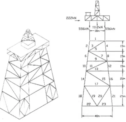
The deep-water offshore platforms of continental shelf are tremendous engineering structures. The height of this platforms reaches to and higher. The weight of structures about 400 000 kN. Therefore, the optimum design of this structure with minimum weight is an actual problem. The block of offshore platform is a space frame construction and is placed under dynamic forces: wind, waves, earthquakes, equipment installed [1], The structures and design scheme of this platform is in fig. 1. In this case the period of natural vibration of the structures becomes co-measurable with the period of external loads. Resonance occurrence is possible. Therefore, dynamic research of this structures is very necessary. Moreover, the block of offshore platform to carry upper structure with drilling oil-derrick, technological equipment and elements of structures are subjected by longitudinal bend and axis force. The structures may lose general stability.
The problem of optimum design is calculated by Lagrange multipliers method, Reileigh correlation [2].
The problem is: minimum weight
n
mm
(1)
where: p -density; A; - cross-section of i-elements; Lj -length of i-elements.
This problem is calculated by stability, dynamic stiffness and displacement requirements. The way of doing this optimisation problem is very popular and widely used in optimal design of structure [2,3,4,5]
Nıjat MASTANZADE
Fig. 1 Structure of offshore platform (a) and design scheme (b) Displacement Requirements
The deep-water offshore platforms are placed under horizontal forces: wind, waves, earthquake, flow, ice e.a. Therefore, displacement requirements are very actually.
The principal requirements are written in form
G,=C,-C, (2.1)
In this
c,
=
wh
H
e-2)
where: {u}', -displacement vector with i-element and force; [/f], -stiffness matrix of i-element.
Optimization Scheme of Offshore Steel Structures Lj
\M
(2.3) simmetrik A 1222 2+ Z2 62 L 46//
L 22 12/z2■7+
~
2 62fl
) L(i
£
2J
6/z L //2 1222 A L~ 62 L 4In this 2=cosa p=sina
The correlation between forces and displacement are calculated from (2.4)
Nıjat MASTANZADE £ L __ EA2 1
o
o
I 12 L2 6 L simmetrik 4 1 1 fix L 1 0 0 1u2
fly A 12 6 A 12V2
m-, 0 ~ L2 L 0 L2h J
6 6 0 2 0 4 L L (2-4)j.S7}.-possible displacement matrix is composed by following principle:
K = (2.5)
where Kab reaction in a-joint from displacement b-joint.
Analytical expression for the optimum cross-section of every element is determined using the term of Lagrangian’s maximum.
L{A, = PA'L~ + E A (C7 -
C
j
)
(2-6), = 1 ./ = !
where Xj -Lagrange multipliers.
To get numerical solution of problem, calculation algorithm and computer program were developed.
Stability
Requirements
The stability requirements are written down in form
G, =//y-«//>() (3.1)
where /n -factic critical force with j-natural mode; //-lesser critical force; ot- coefficient of separate mode.
Optimization Scheme of Offshore Steel Structures
where r|j-natural vector with j-natural mode; Kg -matrix of geometrical stiffness. The matrix of geometrical stiffness Kg depends on internal forces by external force P from stiffness. 0 0 0 0 0 0 6 L_ n _ 6 5 10 V 5 10 2Z2 f) _ L .Lt 15 V 10 30 Kg---g L 0 0 0 6 _ L_ 5 10 1 1 b J 15 _ (3.3)
Dynamics
Stiffness
RequirementsThe dynamics stiffness of structures is calculated by natural frequency. The requirements of frequency is written in form:
g = «72-ai2 (4.1)
where co -minimum frequency of structures.
The value of natural frequency is calculated by Reileigh method
,2
_
M'
WW
W
[
a
/»
(4.2)
where {ç/}-natural vibration mode of structure; [K]-matrix of stiffness system; [MJ- matrix of mass with added water mass. The matrix of mass with added water mass is calculated by Reileigh discrete variation method [6],
The analysis of different calculation algorithm of optimization of structures- SAMSEF, PROSSS, TRUSSORT, SPAR, ACCESS end etc. In thair study, C.Fleury, J. Sobiesrczanski-Sobieski, E.Haug, L.Schmit [2,3,4,5] may come to a conclusion that the principles of all programs are finite elements method including following iteration steps:
fixing the step for modification of cross-section area;
composition of stiffness matrix (geometrical stiffness and matrix mass with added water mass);
white down requirements;
white down displacement (vibration mode, stability mode);
- white down Lagrangian for cross-section Aj+i and as compored with Lagrangian for cross-section Aj;
Nıjat MASTANZADE
Conclusion
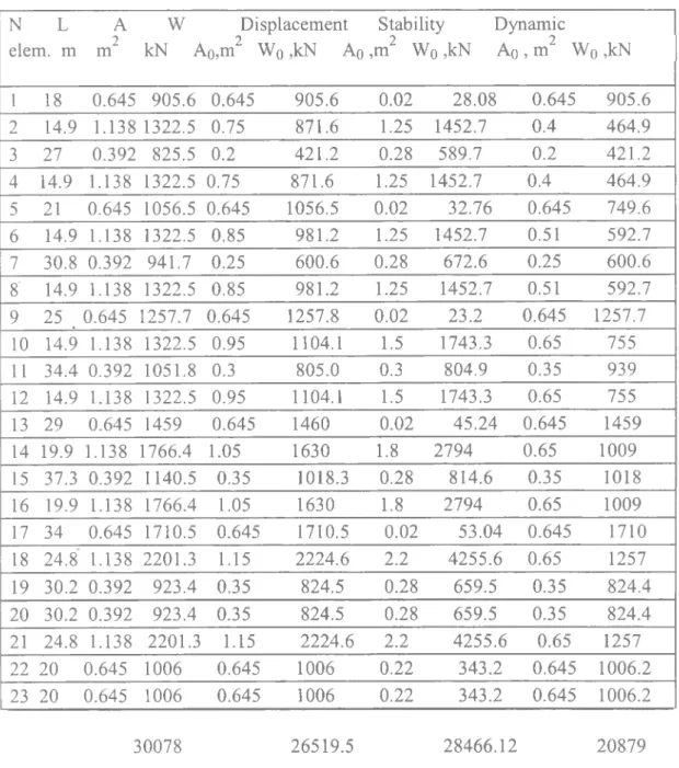
The calculated result of optimum section and weight of elements by displacement, stability and dynamics stiffness are requirements on table. 1.
Table 1
N L elem, m A 2 m W kN A Displacement i0,m2 Wo ,kN Ao Stability Dynamic ,m2 Wq ,kNAq
, m2 Wq ,kN 1 18 0.645 905.6 0.645 905.6 0.02 28.08 0.645 905.6 2 14.9 1.138 1322.5 0.75 871.6 1.25 1452.7 0.4 464.9 3 27 0.392 825.5 0.2 421.2 0.28 589.7 0.2 421.2 4 14.9 1.138 1322.5 0.75 871.6 1.25 1452.7 0.4 464.9 5 21 0.645 1056.5 0.645 1056.5 0.02 32.76 0.645 749.6 6 14.9 1.138 1322.5 0.85 981.2 1.25 1452.7 0.51 592.7 7 30.8 0.392 941.7 0.25 600.6 0.28 672.6 0.25 600.6 8' 14.9 1.138 1322.5 0.85 981.2 1.25 1452.7 0.51 592.7 9 25 . 0.645 1257.7 0.645 1257.8 0.02 23.2 0.645 1257.7 10 14.9 1.138 1322.5 0.95 1104.1 1.5 1743.3 0.65 755 11 34.4 0.392 1051.8 0.3 805.0 0.3 804.9 0.35 939 12 14.9 1.138 1322.5 0.95 1104.1 1.5 1743.3 0.65 755 13 29 0.645 1459 0.645 1460 0.02 45.24 0.645 1459 14 19.9 1.138 1766.4 1.05 1630 1.8 2794 0.65 1009 15 37.3 0.392 1140.5 0.35 1018.3 0.28 814.6 0.35 1018 16 19.9 1.138 1766.4 1.05 1630 1.8 2794 0.65 1009 17 34 0.645 1710.5 0.645 1710.5 0.02 53.04 0.645 1710 18 24.8 1.138 2201.3 1.15 2224.6 2.2 4255.6 0.65 1257 19 30.2 0.392 923.4 0.35 824.5 0.28 659.5 0.35 824.4 20 30.2 0.392 923.4 0.35 824.5 0.28 659.5 0.35 824.4 21 24.8 1.138 2201.3 1.15 2224.6 2.2 4255.6 0.65 1257 22 20 0.645 1006 0.645 1006 0.22 343.2 0.645 1006.2 23 20 0.645 1006 0.645 1006 0.22 343.2 0.645 1006.2 30078 26519.5 28466.12 20879Optimization Scheme of Offshore Steel Structures
The analysis of result may notice that in case stability requirements cross-section of horizontal elements is almost equal to zero. Then we can remove it and so change topological scheme of structures. That is its may throw aside and all topological scheme of structures change. In this variant, cross-section of vertical elements is very large and therefore, its case are no profitable.
The most profitable are case of dynamics stiffness requirement. Economical effect with difference of weight for one panel is calculated: Displacement Requirements Wo-W 100% = 30078-26519.6 30078 100% = 12% Stability Requirements
w(>
-w
100% = 30078-28466.12 30078 100% = 5.3% Dynamics Stiffnessrequirements-w
0 -w
100% = 30078-20879 30078 100% = 30.6% W = Wo References[ I ] Dawson,T.H. (1983),“Q/^/7ore Structural Engineering”, Englewoodcliffs,USA.
[2] Haug E.J. and Arora J.S.,(1979), “Applied optimal design - mechanical and structural system”.
John Wiley and Sons, Inc.New York.
[3] KhotN.S., Sander G.,(1984), “Optimization of structures by the optimality criterion method”,New Direction in optimum structural design,John Wiley and Sons, Ltd.NewYork.
[4] Fleury C., Sander G.,(1983), “Methods for Optizing Finite Element Flexual System”.
Comp. Meth.Appl.Engrg.,y.2Qf\o 1,17-38.
[5] “New Direction in Optimum Structural Design”,(1984) ed.by. E.Atrek, R.H. Gallagher, K.M.Ragsdell, O.C.Zienkiewicz. John Wiley and Sons, Chichester, New York, Brisbane, Toronto, Singapore.
[6] Mastanzade N.,(1995), “Dynamic behaviour of offshore gravity platform”, Asian Journal of
Journal of İstanbul Kültür University 2002/1, pp. 37-40.
A New
Method for
Increasing the
EarthquakeSafety
of the
StructuresSeismic
Isolation
Hasan KARATAŞ*
Abstract
Seismic isolation provides an excellent solution for the earthquake safety of the structures. This paperexplains basic principlesofthis approach.
Özet
Sismik izolasyon, yapıların deprem emniyetinin sağlanması için mükemmel bir çözümdür. Bu makale, sismik izolasyon yaklaşımının temel ilkeleriniaçıklamaktadır.
Keywords Introduction
An earthquake is a natural phenomenon. They are bound to occur at various intervals. The important issue here is to mitigate the loss of lives and possessions by building earthquake resistant structures or by decreasing the effects of earthquake induced forces. Seismic isolation techniquehas been developed greatly in the last 25-30 years. During the 1994 Northridge (USA) and 1995 Kobe (Japan) earthquakes, the buildings with seismic isolation performed extremely well under the earthquake induced forces[l]. These buildings did not collapse and expensive equipment inside was not harmed. These results clearly increased the popularity of the seismic isolation technique. Led by the USA, many nations now require that hospitals, facilities of the fire brigade and telecommunication and bridges that must continue to serve after an earthquake be protected by seismic isolation. In Turkey, the new earthquake code that was revised in 1998 states that seismic isolation can be applied on structures and it is adequate to conform to the American Earthquake Code[3],
Seismic Isolation Method
Seismic isolation technique is based on a simple principle. The seismic isolators placed between the foundation and the vertical load carrying elements, namely columns and where available shear walls, allow the supports to move in the horizontal direction (Figure-1). Therefore by means of seismic isolation, the earthquake acceleration induced on the structure from the ground is decreased up to 80 percent and both the structure itself and the equipment inside is left unharmed
H. Karataş (Figure-2).
Figure-1
Fıgure-3
But without the seismic isolators, the ground accelerations would continue to increase on the upper floors and cause significant horizontal displacements and damage on the structure (Figure-3).
Seismic isolation technique has completed the stages of scientific and technical research and found its rightful place in the earthquake codes. The process is completed by placing ‘ the isolators, which are now produced in many countries, during the construction period in accordance with the structural designs [2], Although it is easier and more economical to place the isolators during the construction period, it is also possible to place them to existing structures to increase their seismic safety.
In Turkey, the seismic isolation technique was first applied at the new terminal building of the Ataturk Airport in Istanbul to provide additional seismic safety after the 17 August 1999 earthquake. However, the seismic isolators were place at the top of columns beneath the supports of the steel roof construction with large spans at the top floor since the construction period was already completed at the time.
Although still in the project stages, preparations are being made to use seismic isolation at some hospitals, telecommunication facilities, factories, domiciles, bridges, overpasses and liquefied natural gas tanks.
Among the structures that must be fortified with seismic isolation, liquefied natural gas tanks are one of the most significant types of structures from the environmental point of view. In Greece, LNG tanks with diameter of 70 meters and a height of 32 meters were provided with seismic isolation to increase their seismic safety.
A New Method for Increasing the Earthquake Safety of the Structures Seismic Isolation
An Application
from
TurkeyStarting with the ones in Marmara Ereglisi, liquefied natural gas tanks at Marmara and Aegean regions must be provided with the seismic isolation to increase their existing seismic safety.
It is natural for the seismic isolation to increase the production cost of a structure. However, superstructure is significantly economized since the earthquake forces are decreased up to 80 percent. As an example, the load carrying components of the ongoing construction of the new terminal building of the San Francisco Airport are made of steel. 600 tons of steel on the superstructure alone was saved thanks to seismic isolation. In this case, the cost of seismic isolation is decreased at a significant rate.
References
[1] Naeim, F.and Kelly, J. , (1999), "Design ofSeismic IsolatedStructures, from
Theoryto Practice", New York, JohnWileyand Sons,
[2] Utku, Ş.,(1998), “Adaptive Structures,FullbrightLectures”, Middle East TechnicalUniversity- Ankara.
[3] SeismologyCommittee, “Blue Book-1999 “,StructuralEngineers Association of California.