Adıyaman Üniversitesi
Fen Bilimleri Dergisi 2 (2) (2012) 49-57
Focusing Properties of Square Lattice Air-Solid Sonic Crystal is Independent of Scattering Material
Serkan Alagöz1*, İsmail Akbaş2 1
Inonu University, Department Of Physics, Malatya, Turkey
2
Inonu University, Electronics and Automation Department, Malatya, Turkey [email protected]
Abstract
A sonic crystal consists of a finite-size periodic array of scatters embedded in a background material. One of the fascinating properties of sonic crystals is to focusing phenomenon. In this study, focusing properties of solid-air 2D sonic crystal lenses with square lattice configuration are investigated for various scattering material. Two-dimensional sonic crystals were constructed with 2.0 cm diameters cylindrical rods of 2.5 cm lattice constant. Band structure of the square lattice arrays was modeled theoretically by Plane Wave Expansion method. Experimental results are presented for square lattice performed by Steel, Aluminum and Perspex rods in air.
Keywords: Sonic crystal, Focusing, Plane-Wave Expansion Method. PACS: 43.20.Bi, 43.20.El, 43.20.Fn
Kare Örgü Hava-Katı Sonik Kristal Yapıların Odaklama Özelliklerinin Dağıtıcı Malzemeden Bağımsızlığı
Özet
Sonik kristal yapılar sınırlı sayıda dağıtıcı malzemelerin periyodik olarak dizilmesiyle meydana gelir. Sonik kristallerin en önemli özelliklerinden biriside odaklama olayıdır. Bu çalışmada, kare örgü konfigürasyona sahip 2D sonik kristal lenslerin odaklama özellikleri farklı dağıtıcı malzemeler için incelenmiştir. İki boyutlu sonik kristaller 2.5 cm kafes sabitine sahip 2.0 cm çaplı silindirik çubuklardan oluşturulmuştur. Kare örgü düzene sahip sonik
50
kristalin band yapısı teorik olarak Plane Wave Expansion metoduyla modellenmmiştir. Deneysel sonuçlar çelik, alüminyum ve plastic çubuklar için gösterilmiştir.
Anahtar Kelimeler: Sonik Kristal, Odaklama, Plane-Wave Expansion metodu. PACS: 43.20.Bi, 43.20.El, 43.20.Fn
Introduction
One of the note worthy application of negative refraction behavior in certain frequency band, was the development of lens structures. Negative refraction of wave beams in the rectangular slab results in wave focusing behind the slab. Negative refraction behavior and imaging effect have been found in photonic crystals [1, 5]. These properties were observed by sonic crystals for acoustic waves [6, 8]. Sonic crystal consisting of a square array of rigid or liquid cylinders embedded in an air background was observed to have the negative-refraction behavior and imaging effect for acoustic wave [9]. It was shown theoretically and experimentally that behavior of sonic crystal lens could be well described by the lensmaker’s formula [10] making sonic crystal slab good candidate for development of acoustic wave focusing devices such as sonar systems and audio speaker systems. There is not enough work considering implementation of sonic crystals device, yet. In this study, we tried to find out how different scattering materials affect sonic lens properties. Because, finding appropriate scattering material is very significant for enhancement of sonic crystal devices.
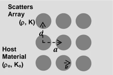
Sonic crystals are made of two-dimensional arrays of rigid cylinders placed in parallel in a medium (See Figure 1). Rigid cylinders are called as scatters and they scatter acoustic wave along the host material and lead a phenomenon so called Bragg diffraction. Propagation of the waves in the host material will be modulated by the periodic structures of scatters and dispersion of waves will no longer behave as homogenous medium. Band structures appear in frequency characteristics. These band structures provide high transmission in certain bands. In the solid-air type sonic crystal slabs, host material is air and scatters may be various solid materials that have various densities and bulk modulus.
Figure 1. Square lattice sonic crystal structure and related parameters. Host Material (o, Ko) Scatters Array (, K) a a R
51
We used square lattice solid-air sonic crystal slabs. For the theoretical study, Plane-wave expansion (PWE) method [10, 15] was used to compare band structures of different scattering material, which are plastic, aluminum and steel bar. For the experimental study, plastic-air sonic crystal slab, aluminum-air sonic crystal slab, steel-air sonic crystal slab were tested to compare their focal point patterns, maximum focusing frequencies and maximum focusing amplitudes.
Numerical Modeling
In homogeneous wave equation for theoretical investigation of acoustic wave band structures was given in normalized form [13] as follows;
0 1 ) ( 2 2 p K p , (1)
where p is sound pressure. is the normalized density and K represents the normalized bulk modulus and defined as
o and o K K
K . (o,K ) and (o , K ) parameters are
used for describing host materials and scattering materials respectively. In Figure 1, u is a
normalized time and expressed as cot [13]. Speed of sound in host material was denoted by c . Second-order inhomogeneous differential equation given in Eq. (1) well defines o
acoustic wave propagation in sonic crystal slab and it was solved to obtain band structure. [10, 13, 14] For the solution, a harmonic form for the sound pressure p(r,u)eikoup(r) was
assumed. Then, Eq. (1) can be rearranged as,
0 ) ( ) ( ) ( )) ( ) ( ( 2 p r r K c w r p r o (2)
Applying the Floquet–Bloch theorem for the periodic system, the spatial function of the pressure is described by p r uk r eikr
) ( )
( , where uk(r) is a periodic function according
to the periodicity of the sonic crystal. Eq. (2) was solved for the periodic function p(r) by PWE method [13]. For this propose, uk(r), (r) and
) ( 1 ) ( r K r
K periodic functions were expanded in Fourier series as:
52 ) ( ) ( i Gr G G e r
(3) ) ( ) ( i Gr G G e K r K
(4) ) ( ) ( ) ( i Gr G G k r k i e u e r p
(5) where, KG,G and ukG are corresponding Fourier coefficients.[15] Eq. (2) was transformedinto finite matrix equation by using Fourier series as:[13-14]
( )( )
0 ' .' ' ' 2
G G G G G G k G k G u K w (6)By solving Eq. (6), wn(k) eigenvalues were obtained for n1,2,3.. to draw band structures of sonic crystal. In the Eq. (6), G is the 2D reciprocal lattice vector. KG and G coefficients
for periodic cylindrical structure shown in Figure 2 was expresed as [15],
0 ) ( ) 1 ( 0 ) 1 ( G G F G f fr r G (7) 0 ) ( ) 1 ( 0 ) 1 ( G G F K G f f K K r r G (8) where, c r A R f 2
is filling ratio of sonic crystal for R radius of cylinders and Ac primitive
cell area. F(G) function is called as structuring factor and calculated by;
R G R G J f G F r ( ) 2 ) ( 1 (9)
where, J1(x) is the Bessel function of the first kind of order one. In the next section, we will discuss the effect of various scattering material.[15]
53
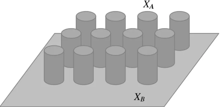
Figure 2. Periodic cylindrical structure with (A,B) two levels of material parameter.
Effects of various scattering materials
Normalized material parameters of scattering rods for perspex, aluminum and steel with respect to host material air were given in Table 1.
Scattering Materials K
Perspex 1.01 x10⁻⁶ 2.06 x10⁻⁸ Aluminum 4.44 x10⁻⁷ 1.97 x10⁻⁹ Steel 1.53 x10⁻⁷ 4.77 x10⁻¹⁰
Table 1. Normalized material parameters (, K ) for various scatters.
As seen in Table 1, normalized material parameters (, K ) for the perpex, aluminum and steel have very small values. When these small values are considered, Eqs. (7) and (8) approximate following equations;
0 ) ( 0 ) 1 ( G G F G fr G (10) 0 ) ( 0 ) 1 ( G G F G f K r G (11)
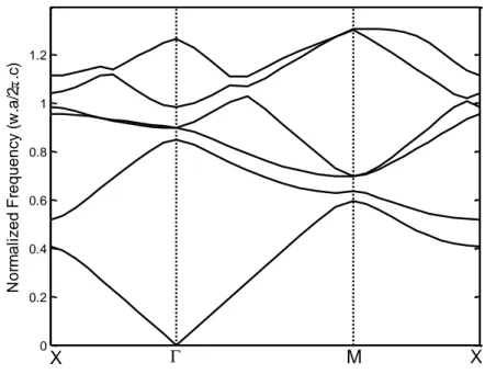
Clearly seen from Eqs. (10) and (11), materials listed in Table 1. yield quite similar Fourier coefficients. As a consequence, it makes the band structure of sonic crystals almost the same. Band structure drawing for these materials was given in Figure 3. One can easily state that various scattering material listed in Table 1. did not change frequency depended properties of square lattice air-solid sonic crystal lens. According to Eqs. (10) and (11), structural parameters of sonic crystal such as filling ratio, lattice constant, radius of cylinders are effective in determining band structures.
XA
54
From the Figure 3, negative refraction was observed at second band for squared lattice sonic crystal slabs with various scattering materials. (Lattice constant a25 mm, filling ratio fr 0.50). Being convex at Γ in range of 0.63-0.85 normalized frequency suggest that sonic crystal slabs have negative refractive index for acoustic wave resulting in all sonic crystal slabs behave as a lens and focus the wave at these frequencies in range of 0.63-0.85.
0 0.2 0.4 0.6 0.8 1 1.2 N o rm a li ze d F re q u e n cy (w .a /2 . .c) X M X
Figure 3. Band structure of squared lattice sonic crystal for different scattering material listed
at Table 1. Lattice constant a25mm, filling ratio fr0.50 and speed of sound 340
o
c m/sn.
Experimental Study
For the different scattering material listed in Table 1, square lattice sonic crystal lens (lattice constant a25mm, radius of cylinders R10mm, height of scattering rods h32
cm) was tested by using the experimental setup shown in Figure 4.
Focal points pictures were obtained by scanning two dimensional measurement zone seen in Figure 4. Experiment set described in the figure was made of measurement zone (mechanization), Input-Output Cards (Signal Conditioner, Digital-Analog Converter, Amplifier) and computer (Labview software). Scanning was done in 4056 cm2 area by 0.5 cm steps. In order to reduce noise, five measurements were carried out for each point in the measurement zone and average values were taken to draw focal point pictures. Measurements were conducted by 3 ms delay after sonic transceiver emitted.
55
Two dimensional square lattice sonic crystal is fabricated 14x14 array of rods with a periodic lattice constant of 2.5 cm, a cylinder radius of 2 cm, rods height of 32 cm. Experimental studies were performed by Steel, Aluminum and Perspex rods in air.
Figure 4. Experimental setup.
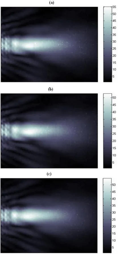
Obtained focal point pictures for different scattering materials are illustrated in Figure 5. Wave frequencies resulting maximum focal point intensity for all scattering materials were obtained at roughly 9900 Hz. Focal point intensities, which is an important focusing device property, did not show a considerable change. Focal point patterns are quite similar for all tested scattering material (See Figure 5).
Microphone Sonic Transceiver MEASUREMENT ZONE COMPUTER Measurement Control STEPPER MOTOR x y x Signal Conditioner Amplifier Digital-Analog Converter Data Acquisition Aquation Signal Processing Graphical User Interface S o n ic C ry st a l
56
Figure 5. Focal point pictures for different scattering materials at 9900 Hz. (a) Air-aluminum
sonic crystal lens focal point picture, (b) Air-steel sonic crystal lens focal point picture, (c) Air-perspex sonic crystal lens focal point picture.
57
Conclusions
We have studied focusing effect for acoustic waves in two-dimensional sonic crystal consisting of square arrays of different density cylinders in air. This study showed that solid scattering materials, which have different densities, did not change square lattice sonic crystal lens properties. For practical applications, design of square lattice air-solid type sonic crystal lens can be done according to production preferences such as cost and portability rather than material property. The other point to be considered is that structural parameters (filling ratio, lattice constant, radius of cylinders) act on focusing properties of air-solid type sonic crystals more dominantly than material parameters. It was theoretically demonstrated by Eqs. (10) and (11).
References
[1] H. Kosaka, T. Kawashima, A. Tomita, M. Notomi, T. Tamamura, T. Sato, S. Kawakami,
Phys. Rev., 1998, E 58, R10096-R10099.
[2] M. Notomi, Phys. Rev., 2000, B 62, 10696-10705.
[3] C. Luo, S. G. Johnson, J. D. Joannopoulos, J. B. Pendry, Phys. Rev., 2002, B 65, 201104-1-201104-4.
[4] E. Cubukcu, K. Aydin, E. Ozbay, S. Foteinopoulou, C. M. Soukoulis, Nature, 2003, 423, 604.
[5] X. D. Zhang , Z. Liu, Appl. Phys. Lett., 2004, 85, 341.
[6] L. Sanchis, A. Hakansson, F. Cervera, J. Sanchez-Dehesa, Phys. Rev., 2003, B 67, 035422.
[7] N. Garcia, M. Nieto-Vesperinas, E. V. Ponizovskaya, M. Torres, Phys. Rev., 2003, E 67, 046606.
[8] B. Gupta, Z. Ye, Phys. Rev., 2003, E 67, 036603.
[9] C. Qiu, X. Zhang, Z. Liu, Phys. Rev., 2005, B 71, 054302. [10] C. H. Kuo, Z. Ye, J. Phys. D: Appl. Phys., 2004, 37, 2155–2159.
[11] E. N. Economou, M. M. Sigalas, Phys. Rev., 1993, B 48, 13434–13438. [12] M. M. Sigalas, J. Appl. Phys., 1998, 84, 3026–3030.
[13] T. Miyashita, Meas. Sci. Technol., 2005, 16, R47–R63.
[14] L. Feng, X. P. Liu, Y. B. Chen, Z. P. Huang, Y. W. Mao, Y. F. Chen, Jian Zi, Y. Y. Zhu,
Phys. Rev., 2005, B 72,033108.
[15] I. Perez-Arjona, V. J. Sanchez-Morcillo, J. Redondo, V. Espinosa, K. Staliunas, Phys.