Atomic theory
of
scanning tunneling
microscopy
E.
Tekman andS.
CiraciDepartment ofPhysics, Bi lkent University, Bilkent, 06533Ankara, Turkey (Received 11 April 1988;revised manuscript received 3February 1989)
We present a quantitative analysis ofthe modifications ofthe scanning-tunneling-microscopy im-ages due to the local perturbations ofthe electronic states induced by the tip in close proximity to the sample surface. Using an empirical tight-binding method, we have calculated the electronic states ofa prototype tip-sample system consisting ofa single-atom tip and the graphite surface, as a function ofthe tip-sample distance. We find that as the tip approaches the sample, their states start to interact and become laterally confined in the vicinity ofthe tip at small tip-sample separation. These states influence the tunneling phenomenon byconnecting the tip and sample surface electron-ically. The effect ofthe tip-induced localized states is discussed, and the expression for the tunnel-ing current isreformulated by incorporating the tip-induced states. Calculations using this expres-sion show that the corrugation amplitude obtained from scanning tunneling microscopy isenhanced and deviates from the proportionality to the local density ofstates ofthe bare sample at the Fermi level evaluated at the center ofthe tip.
I.
INTRODUCTIONReal-space imaging capability and atomic-scale resolu-tion are unique features that make scanning tunneling mi-croscopy' (STM) a powerful technique in the analysis
of
surfaces. In the current theory
of
STM, TersoA and Hamann replaced the many-particle wave functions in the Bardeen formalismof
tunneling by the one-electron statesof
infinitely separated electrodes. Using this ap-proximation the expressionof
the tunneling current can be cast into a simple form, and is found to be propor-tional to the local densityof
statesof
the bare sample at the Fermi level evaluated at the centerof
the tip, p(ro, Et;);in the usual STM experiments the tip-to-surface distance, d, is large and thus this theory with the nonin-teracting electrodes has been used with reasonable suc-cess."
Recent experiments, ' ' however, have indi-cated that the tip-sample interaction isan essential aspectof STM.
The STM studyof
the graphite surface at avery small bias voltage' has indicated an elastic deformationof
the surface caused by the tip. In this case a tip-to-surface distance as small as=2
A is conjectured, where-by a local and strong interaction between the tip and sur-face sets in, which leads to huge corrugations. Self-consistent force and charge-density calculations by Ciraci andBatra'
have justified the strong interactions induced by the tip. They showed that at small d=1.
5 A the tun-neling barrier recedes and a point contact through a chemical bond between the tip and surface atoms is formed. Recently observed STM corrugations on the close-packed(l
l1) surfaceof
the noble' and simple' metals, which are much larger than the corrugation am-plitude obtainable from p(ro,EF),
provide evidence also for the strong tip-sample interaction, whereby the com-monly accepted proportionality to the electronic struc-tureof
the bare sample surface is no longer valid. At present the interactionof
the tip with the substrate atoms has become the focusof
attention on accountof
newareas
of
application brought about by the recent stud-ies''
of
STM combined with atomic force micros-copy.'As the tip approaches the sample surface, the tip-sample interaction gradually increases, and the potential barrier islowered. The charge density undergoes a redis-tribution, and the ions
of
the tip and sample are displaced from their original positions to attain the lowest total en-ergy.It
is therefore expected that the STM images are aA'ected by these modifications over the electronic and atomic structureof
bare sample and bare tip. This study presents the first quantitative analysisof
the mod-ificationsof
the STM images induced by the local pertur-bationsof
the electronic states. In the first partof
the pa-per, we have investigated the eA'ectof
the tip-sample in-teraction on the electronic states. Based on the empirical tight-binding(ETB)
calculations on a prototype graphite surface, we demonstrate that the tip interacting with the sample surface induces localized (or resonance) states. That the tip-induced localized states (TILS)are formed at the vicinityof
the tip was pointed out first by ourselves, and reported elsewhere as a preliminary resultof
the present study. ' In the second partof
this paper we study how the STM images are inAuenced by the local pertur-bations in the electronic structure.To
this end we refor-mulate the expressionof
the tunneling current to includeTILS.
Calculations using this new expression show that the corrugation amplitude obtained from STM deviates from that related to p(ro,EF
).Based on the present analysis we are able to identify three ranges for the tip-sample distance, which lead to three diAerent regimes in the operation0
of
STM for the graphite sample.For
large d(d
~4
A) the tip-sample in-teraction is insignificant, and may be represented by the sumof
the attractive van der Waals energy and repulsive Pauli exclusion energy yielding aweak attractive interac-tion. The theory, which is based on the Bardeen transfer Hamiltonian approach and yielding that the tunnelingcurrent is proportional to p(ro, EI;), can be used safely in this range
of
d. This modeof
operation is called the nor-mal tunneling (or nearly independent electrodes) modeof
STM.
For
relatively smaller d(2Sd
(3.
5 A)TILS
be-come pronounced, and thus the tunneling current is modified. The mode corresponding to d whereTILS
are effective is called theTILS
mode. Upon further decreas-ing d, the potential barrier between the tip and sample is perforated by an orifice, whereby the characterof
TILS
changes by the enhanced localization near the dividing plane, and by their energies lying below the Fermi level. The mode
of
operation corresponding to very small d which is comparable with the interatomic distance (d 2 A) is the point-contact mode. In this mode the natureof
the conductance israther different from that occurring at normal tunneling mode, and can be described as a quan-tum conductance through the channels
of
the constric-tion states belowE~.
A detailed analysisof
this mode will be reported subsequently.In
Sec.
II
we explain the model for the tip-sample sys-tem and the detailsof
theETB
method as used in our study. The resultsof
these calculations are discussed inSec.
III
with the emphasis placed onTILS.
In Sec. IVwe explain the detailsof
the formalismof
the tunneling current, in whichTILS
are incorporated. The enhance-mentof
the corrugation amplitude to be obtained from STM operating in theTILS
mode isalso exemplified for a typical case in the same section. Our findings are sum-marized in the concluding section.II.
ELECTRONIC STRUCTURE OF THE TIP-SAMPLE SYSTEMIt
is known that the bulk graphite has a layered struc-ture with a weak interlayer coupling. Since the atomic positions in the consecutive layers are shifted, two ine-quivalent atomic sites occur in a given layer. These sites are usually denoted as the A andB
sites. The3
site has carbon atoms directly below and above it in the adjacent layers, whereas theB
site does not. In each layer one typeof
site has three nearest neighborsof
the other type site, and thus hexagons are formed from the alternating sites. The centersof
these hexagons are denoted as theH
site. While an individual graphite layer (unsupported monolayer) has sixfold rotation symmetry with zero charge density at theH
site and with the Fermi surface collapsed to a single point at theK
pointof
the Brillouin zone (BZ), the symmetry is lowered to threefold rotation, and the Fermi surface becomes small pockets in the graphite slab. This symmetry lowering due to interlayer interaction has been resolved by STM operating at large d, as such that only three protrusions outof
six atomic sitesof
the surface hexagon (which are formed by the3
andB
sites) have been observed. Based on the Tersoff-Hamann theory it was argued that' theB
sites, for which p(ro,E~)
is larger than thatof
the A sites, are more likely to be probed bySTM.
By contrast, both3
andB
sites can be resolved equivalently in STM (Ref. 21) operating at small d. This implies that the atomic scale interactions occurring between the tip and sample at small d dominate the tunneling current, so that the weak(2.1)
y, (k,
r)=
—
pe
"'
P,(r
—
R„r),
—
where P; stands for the 2s- and2p„,
-type Wannier or-bitalsof
the carbon atoms with the position vector ~ in the unit cell.R„
isthe Bravais lattice vectorsof
the hex-agonal monolayer lattice. InETB
no specific useof
orbit-als ismade, but the energy parameters for the on-site and nearest-neighbor matrix elements in the secular equation[Ho(k)
—
IEO(k)]ao(k)=0
are fitted to the existing band structure.To
this end, we used the band energies calcu-lated by Tatar and Rabii and determined the energy pa-rameters, which are listed in TableI
with the notation given by Slater andKoster.
The in-plane orbitalsof
carbon atoms
(Pz„P»,
and Pz ) hybridize intosp-X Py
hybrid orbitals and form 0 and o'*bands. The
p»
orbit-z
als, in turn, form
~
and~*
bands. In the monolayer geometry these two setsof
states are decoupled owing to the reAection symmetry about the layer plane. TheFer-mi level occurs at the
K
cornerof
the graphiteBZ,
where the m and sr* bands cross and EI;= —
8eV.TABLE
I.
The empirical tight-binding parameters for the graphite monolayer fitted to the band-structure calculations of Tatar and Rabii (Ref. 22). The notation is taken from Slater and Koster (Ref. 23). Superscript 0 (1) designates the on-site (nearest-neighbor interaction) energies. All parameters are in eV.E,,
—
10.73 0 Epprr—
6.13—
5.41 1 Espo 5.59 1—
2.02 1 Epprr 5.84 interlayer coupling distinguishing two different sites be-comes only a secondary eftect. Since the main featuresof
the electronic structure
of
graphite are determined by thatof
a single monolayer, and since the present study deals with a small tip-to-sample distance, the graphite sample is represented by a graphite monolayer in our model. We note that in this simple model the3
andB
sites become identical and are denoted as the on-top site (orT
site) in the restof
the paper. In viewof
the compu-tational limitations, calculations are performed with periodically repeated supercells. The tip is represented by a single carbon atom, which is periodically repeated in a(3X3)
array. Then the whole system is treated in a (3X3)supercell consistingof
one carbon atom represent-ing the tip, and nine graphite monolayer cells represent-ing the sample. In this model the repeat periodof
the tip atoms is7.
25A, which is large enough to lead to negligi-ble intertip interaction. The artificial periodic-boundary conditions allow us to use the Bloch sums constructed from the orbitalsof
carbon atoms. The representationof
the tip by a single carbon atom is appropriate and suits the purpose
of
this study because the sample interaction is determined mainly by the outermost atomof
the ex-tended tip at small d.The electronic band structure
of
the unsupported graphite monolayer is calculated by using theETB
method. Formally, the wave functions are constructed from the Blochsums:Having determined the energy parameters
of
the graphite monolayer, we next consider the tip and sample system in the (3X3) supercell. The tip being represented by a single carbon atom, its orbitalsP„~($2„$2~
)in-X,+,2
teract mainly with the
a
and m* statesof
the monolayer.The interaction energy is given in terms
of
the matrix ele-ment &Q„~HT+s
~P,&of
the tip-sample HamiltonianHT+s
with respect to the tip(P„„),
and the sample(P,
)orbitals. Depending upon the position
of
the tip atom above the monolayer, these interaction energies may de-viate from the nearest-neighbor matrix elementsof
the bare graphite monolayer given in TableI.
Then the in-teraction energies are determined by scaling the nearest-neighbor matrix elementsof
the bare graphite with Slater-type orbital functions:=
&P,
,;IHoI&„&epx[
—
p;J(r,
,
—
ao)],
(2.2) where r; and ao are the internuclear distances in the right-hand and left-hand side integrals, respectively. The exponentsof
the Slater-type orbitals are obtained from the wave functions given by Clementi and Raimondi.p2q pq
=
.
, p2p 2p=
. , p2q pp=
(p2,z,+p2~z~
)/2.
In the past, such a scalingof
thein-teraction parameters has been applied to other systems successfully. As for the on-site matrix elements (or self-energies
of
the tip orbitals),E;,
=&/„~Hz.
+s~P„
they are shifted to coincide with the Fermi level
of
the extended tip, which is biased relative to the monolayer. This way, the featuresof
the macroscopic tip are incor-porated into our model, simulating the tip by a single atom.states localized at this orifice can be considered as the constriction states leading to the quantum conductance. Therefore the character
of
the conductance in this regime undergoes a dramatic change. The point-contact regime itself has many interesting features''
such as the one-dimensional conductivity, but it is beyond the scopeof
the present study.
For 2.0
~
d+ 3.
5A the interaction energy is not strong enough to form a chemical bond, but is significant to lead to the intermixingof
the tip atom and monolayer states. Owing to the supercell used in the calculations, theK
point
of
the graphite BZis folded into theI
pointof
the supercellBZ.
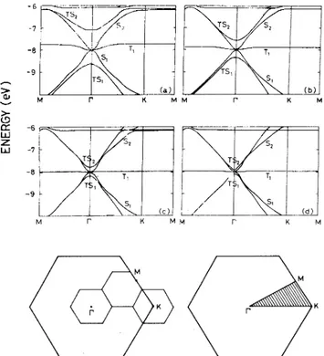
The band structuresof
the tip-graphite monolayer system are shown inFig.
1for d ranging from 2to2.
75A.
It
isclear that the tip and sample states hy-bridizeif
~E,E„~
—
is small and the matrix element&
g„~HT+s
~g,& is large.For
the model described in Sec.II
these two conditions are satisfied around the centerof
the (3
X3)
BZ(I
point). At this point, we observe that the statesTS,
and TS2approach the Fermi level as d in-creases. The analysisof
the wave functionsof
these states reveals that they have more weight in the vicinityof
the tip, and have weak bonding and weak antibonding char-acters, respectively. Therefore, the states(TS,
and TS2 nearI
point) are identified asTILS,
and the rangeof
d, for whichTILS
are active, is called theTILS
regimeof
STM.
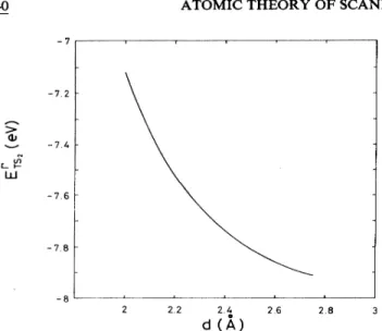
InFig.
2, the energyof
the band, TS2 at theI
point is shown as a functionof
d.It
is clear that theIII.
TIP-INDUCED LOCALIZED STATES The electronic energy structure is calculated for the system consistingof
the graphite monolayer and the tip atom located above various placesof
the surface(T
site,H
site, and bridge site) with varying d. The bias voltage between the tip and the monolayer is taken to be infinitesimal. Depending upon the valueof
d, we can identify three different regimes (i.e.
, the point contact,TILS,
and nearly independent electrode or normal tun-neling regimes) which intermix in a wide rangeof
the border valueof
d.The interaction energy &P„~~HT+z~P,& decays
ex-ponentially with the increasing tip-sample distance, and is negligible for the tip heights d
3.
5 A. As a result, the band structureof
the tip-sample system isjust the projec-tionof
the tip bands on the band structureof
the graphite monolayer. The tip and sample can be considered in-dependent, and thus the formalism developed by Tersoff and Hamann for the tunn'cling current works well. This regime is called the nearly independent electrode regime. On the other hand, for d~
2.0
A, a strong chemical bond forms between the tip and sample atoms. In compliance with the resultsof
the self-consistent field calculations, ' this small d region is identified as the chemical bond (or point-contact) regime, in which the tip and sample are connected by an orifice in the potential barrier. The(a) M M CC -6 UJ z,' -7 -8 (c) &d) K M
FIG.
1. Band structure for the tip located at the on-top posi-tion: For tip heights (a) 2.0A, (b) 2.25 A, (c) 2.50 A, and (d)2.75 A. The labeling isexplained in the text. The graphite BZ
and the 3X3folding is shown inthe lower left corner and the ir-reducible part ofthe supercell BZ is shown in the lower right corner.
—7.2 (A LU —7. 8 2.2 I 2.4 (j
(A)
2.8FIG.
2. Energy ofTS2 at the center ofBZ(I
)as a function ofthe tip-surface distance d. The tip isatthe on-top position.where the orbitals
of
the alternating sitesof
the hexagons in the graphite slab (either only A or onlyB
sites) are in-diff'erence between theTILS
energy and the Fermi levelof
the monolayer isan exponentially decaying functionof
d.
The decay exponent is found to be0.
83A which is very close to the valueof p
used for scalingof
theETB
parameters, confirming that the interaction is strongly lo-calized in the vicinityof
the tip atom.The formation
of
TILS
is more than a weak perturba-tion, and involves the mixingof
the sample and tip states. Becauseof
the potential barrier (which is lower than the vacuum level, but is still above the Fermi level)TILS
have usually more weight either on the tip atom, or on the sample side, when their energies are close to the Fer-mi level. However, the
TILS
located far above the Fermi level may have significant weight across the barrier.If
the tip-sample interaction gets stronger and the potential barrier is collapsed by a local orifice, certain
TILS
dip in the Fermi level and become strongly localized. This cor-responds to the transformationof
TILS
into the constric-tion states, and thus to the transition from theTILS
re-gimeto
the point-contact regime. Another important point we would like to emphasize is thatTILS
become resonance states when their energies lie in the band con-tinuaof
the sample or the tip. This is the situation one encounters at the graphite sample. However,TILS
are expected to be more localized, and to lead to more dramatic effects for a semiconductor sample.In addition
to
theTILS,
states (labeled asS„T&,
and Sz)which are dominated by one typeof
the electrode (tip or sample) are also visible in the energy bands shown inFig. 1.
At the centerof
the supercellBZ,
threeof
the states at the Fermi level originate from the sample states only. In the absenceof
the tip, at the Fermi level,~
and states are degenerate and four linearly independent solutions can be written in the form1/2
2
g
K(r)=
eluded in the summation and
kz
isthe wave vector corre-sponding to oneof
theE
pointsof
graphiteBZ.
(It can be shown that only fourof
these six functions are linearly independent. ) Upon the inclusionof
the tip at theB
site, three linear combinationsof
these states (two3-site
states and the antisymmetric combination
of
the B-site states) are found such that they do not interact with the tip. The fourth linear combination (the symmetric com-binationof
the B-site states) interacts with the tip orbitals and forms theTILS.
This combination has the maximum amplitude on the atom just below the tip (i.e.
,for the on-top positionof
the tip), and the amplitude decreases away from this site. This shows that the tip-induced states are localized.For
the tip atom located at the0
site the degeneracyof
the m and m.*states do not split. This isadirectconse-quence
of
the symmetryof
the model used to simulate the tip-sample system. The effectof
the tip at theH
site seems to be small for the carbon atom representing the tip. The tip atom located at the bridge site yields the effect similar to that at theB
site. However, the strengthof
the interaction energy issmaller owing to the larger in-ternuclear separation. In the present study, the effectof
the tip on the electronic structureof
the sample has been discussed only for the states near theI
pointof
the su-percellBZ,
which are more likely to interact. However, important interaction may occur in the other regionsof
the BZ (for example, near the
M
point) depending upon the characterof
the tip atom and the valueof
d as well.IV. THETUNNELING CURRENT INTHE PRESENCE OF TILS
In the theory
of
STM developed by Tersoff and Hamann, the tip-sample interactions were disregarded, and thus the bare (unperturbed) sample and bare tip states were used. Consequently, the applicationof
this theory is restricted to large d, which we identify as the normal tunneling regime. As revealed by the analysis presented in the preceding section, however, the atomic scale interactions become dominant leading to significant perturbationsof
some sample and tip states. We show thatTILS
form as a resultof
the tip-sample interaction. Therefore one expects that the tunneling current deviates from that predicted by the Tersoff-Hamann theory. In the past the formulationof
the tunneling phenomenon between the interacting electrodes has been the major effort. The applicationof
the existing, more rigorous theories, which go beyond the transfer Hamiltonian ap-proach (THA) to treat the interacting electrodes, are hin-dered by the boundary conditions. Here we develop a formalism for the tunneling between the interacting tip and sample by extending the THA to incorporate the effectsof
TILS.
We start with the THA, because we note that in a real STM the tip creates a local perturbation on a large sample surface. Accordingly,TILS,
which appear as localized in the vicinityof
the tip, contributeto
the tunneling current by modifying the local densityof
states at the Fermi level.In view
of
the above arguments, the time-dependent wave function describing the tunneling event can bewrit-ten as
tII(r,
t)
=a„(t)e
'"
lit„+
g
b,(t)e
—iEIiLSt/+
g
bTILs(t)e PTILsTILS
(4.1)
LIItTILs(
r
) +TILsPTILs( )+
RTILs (4.2)RTILs denoting the local environment
of
the tip atom, used in Sec.II.
It
is clear that 11TILscan be written as alinear combination
of
{tttt, I and {ttr,I,
which alreadyform an overcomplete basis set. However, to investigate the eff'ects
of
the atomic scale interactions on tunneling, we write them explicitly as the third term inEq.
(4.1). This form isalso consistent with the original THA, where different tip or sample states, being orthogonal, are treat-ed independently in the current calculation, but overlap-ping tip and sample states are coupled to each other by a transfer Hamiltonian. In our study the states denoted asTILS
are good solutionsof
the Schrodinger equation[Eq.
(4.2)]in a region different from the tip and sample regions(R„and
R„respectively)
so they are not orthogonal to the existent basis {f„
IUIg,
I.
Here, the wave functions
li„and
lit, are the eigenstatesof
the bare tip and bare sample Hamiltonians, respectively. The states strongly localized around the tip are treated as
TILS.
However, the dividing line is not sharp forweakly perturbed states (e.g., bands originated from the tip 2p and 2p orbitals inSec.
II)
and these are grouped under{ttt„ I and {ttt,I
.
Nevertheless, including these into{QTILsI will not effect the essential results. The extension
to
the Bardeen formalism isthe inclusionof TILS,
which satisfiesIn Eq. (4.1), the initial conditions such as
a„„(
—~
)=
1, b,(—
oo)=0
are imposed in order that thewave function
%(r,
t) to represent a transition from the statell„
to the sample state lij,.
Hence, the tunnelingprobability into the state 11', is
p„p,
=
~b, (~
)~ .To
un-derstand the roles
of
strongly perturbed states both occu-pied and unoccuoccu-piedTILS
(e.g., TSI and TS~ discussed earlier, respectively) are considered. An important point to emphasize at this stage is that the periodically repeat-ing tip-sample system, and the tip represented by a single atom are the only approximations involved in determin-ingTILS.
For
a very large supercell with a single tip atom,TILS
appear as resonances around Ez"-z1 and E~z2 in the densityof
states.It
should be noted that such bands may occur not only alongI
K,
but also in the other regionsof
theBZ.
In fact, self-consistent field pseudopo-tential calculations on the Al-tip and graphite sample have revealed that at certain tip-sample distanceTILS
near the
M
pointof
the graphite BZ can have even more dramatic effects. We next include the effectsof
the transfer Hamiltonian by using the time-dependent pertur-bation theory. The Schrodinger equation describing this tunneling event is(4.3)
In this equation and in
Eq.
(4.2),H
isthe total Hamiltoni-an consistingof
interacting electrode contributions and a transfer Hamiltonian responsible for tunneling. Thus, it differs from the local interaction Hamiltonian Hz-+& used in Sec.II.
Inserting the wave function given by Eq. (4.1) inEq.
(4.3)one getsti
—
ti gatiX
s—
s WsX
TILS (—
TILS)1TILSS TILS
—iE„ /A' ~ —iE t/A ~ —iE~iLSt /'Il
I'Itat;pe ttrt;p+
y
i'fib,ey,
+
S TILS
(4 4)
Using a first-order time-dependent perturbation approach, one sets
a„.
(t)=1,
a„.
(t)=0,
and b,(t)=0.
Also for unoccupied (occupied)TILS
bTILs(t)=0
[bTILs(t)=
1and bTILs(t)=0].
Therefrom one obtains—iEtj t/
TILS' ~ —iEt/fi
.
~ —iE~(Lst/AtipWtip+
2
e(H
+TILs')WTILs'2
~bs 4s+
2
t~bTILs ttTILsTILS' S TILS
(4.5)
It
is apparent that the occupiedTILS
are behaving like tip states (from which tunneling occurs), and the unoccupied ones are coupled to the sample states (into which tunneling occurs). We will find out below that this resemblance isiEt/fi IE t/fi
manifested in the current expression as well. Multiplying Eq. (4.5) from left by e
'
ttt, (or by e ' QTILs in the caseof
unoccupiedTILS)
and integrating over the whole space, two setsof
equations are found:Occ
e ' "p
'
f
d rps*(H—
Etip)t)'j„p+g
e ''
f
d"
o.
*(H
ETILS')PTILS-TILS'
unocc
TILs s
f
d3&yey
=iItbTILS+i@'
g
b,e'
""
f
d'l.
=iamb, +i%'g
bTII.seTILS
—&(E —E )t/fg p
p.
OCC —i
(E&&LS, Ez&LS )t/A 3
f
"
PTILs(—
t p)gtip+ OILS(—
TILS')1TILS' TILS'(4.6a)
Finally
Eq.
(4.6) can becast into a matrix form:r
s'
—
bs ~TILSS
—
S-t1PM
1 l'6—
TILS-tip occ—
s-TILS'+&
TILS TILS (4.7)where
S
is (NTILS XN, );b„M,
„.p and Ms-TILS' MTILS-tp d MTILS-TILS'(1
XNTILS )matrices. Their elements are defined as (Es ETILS)t/A y3 yItc gS=e
«
V'TILSV' (4.8a)(4.8b) tip TILS —
i(E.
—E )t/A TILS-tip XJd'r
PERILS(H—
E«p)Lip I'( ETILS E)tjAI
-TIIS'=e
Xf
d rg,*(H
—
ETILS')PTILS' (4.8c) (4.8d) TILS' TILS~TI
LS-TILS'«PTILS(H
3 +TILS'WTILS' . (4.8e)In
Eq.
(4.8) the subscripts corresponding to the specific elementsof
the matrices inEq.
(4.7) are suppressed.The square matrix on the left-hand side
of Eq.
(4.7)can be inverted to find b, and bTILs. Then the tunneling current can be found by adding all the average transition rates for each tip state, and integrating this quantity over the Fermi surfaceof
the tip. The resulting expression is complicated and requires a detailed accountof
the elec-tronic structure. Further in this section we will present a simplified formof
it to show the qualitative trends. Be-fore doing this we would like to comment on some impor-tant points.(i)
For
a finite bias, it is not possible to haveTILS
be-tween the Fermi energiesof
the two electrodes since oth-erwise there would be a continuous Aowof
electrons be-tween the electrodes. However, such a situation may arise in the point-contact regime, in which the current between the two electrodes has a nontunneling character, and requires atreatment beyondTHA.
In the restof
this section we disregard this situation by neglecting the second term on the right-hand sideof Eq.
(4.7).(ii) Equation (4.7) manifests two different effects
of
empty
TILS
on tunneling. First, the nonorthogonalityof
sample and
TILS
states changes the current via the inver-sionsof
the left-hand side coefficient matrix in Eq. (4.7). In addition to this, the interactionof
TILS
and tip states is also present in the final expression, denoted bytip These contributions disappear when
S
~
0,which indicates the independent electrode regime.
For
this case the unoccupied
TILS
are not localized states in the vicinityof
the tip, but are unperturbed tip states. Another possibility is tohave some elementsof
S
equal to~ 1 1
b,
=
.
I& (1
—
NS
)(Ms-ti
S
MTILS-tip ) (4.9)where
S
is the overlap matrix element for theTILS
atI
point, and clearly MTILS„p is the same for all points in theBZ.
Defining s, ms tip andI
TILStip as thetime-independent factors
of
the quantities defined inEq.
(4.8), the tunneling probability from the tip state g„. into the sample stateg,
is found by the integration with respect totimeunity, which leads to a zero determinant for the coefficient matrix.
For
this caseTILS
are unperturbed sample states. Therefore, the caution has to be exercised in counting the sample states. Upon inversionof
the left-hand side matrix and integration over time, the time-dependent exponents inEq.
(4.8) will combine to give Dirac 6functionsof
energy differences. —i(Eti —ETILS)
(iii) Inverting
Eq.
(4.7) one gets bTI„S~e
and the time integration leads to ptp=
lbTIIs(~
)l
~
&(&tip ETIr.s)
=0
sinceE„.
p
=Ez
WETILs. Thus the current sinks into the sample states, but not the
TILS.
This shows that the energy is con-served. Nevertheless, being nonorthogonalTILS
and the tip (sample) states interact. The energy conservation is relaxed for time intervals smaller than (lETILs EFl/A—) ' and unoccupiedTILS
act as virtualstates through which electrons can transfer from ihe tip into the sample.
To
demonstrate the effectof TILS
on the observed cor-rugation we will use the resultsof Sec.
II
in a simplified form to calculate the tunneling current for a graphite sample.It
is clear fromFig.
1 that the states related to the tunneling event are the sample states at the Fermi level and unoccupiedTILS
aroundI
denoted as TS2.To
obtain the exact result for the tunneling current, one has to include all these localized states in the matrices in
Eq.
(4.7). Here we will rather use an approximate method to simplify calculations, and thus to reveal the qualitative trends. Owingto
Bloch normalizationof
the sample states [Eq. (2.1)] and the localized natureof TILS
and the tip states, lSl and lM, „.„l are on the orderof
I/&N,
that is the effectof
the individualTILS
is negligibly small inEq.
(4.7). Nevertheless, the tunneling current isenhanced significantly when allTILS
in the wholeBZ
are con-cerned.To
this end, we will approximate the band la-beled TS2 by a Oat band at energy E~z with thecorre-2
sponding
TILS
wave function QTILs(r). This approxima-tion will lead to an overestimationof
the effectsof TILS,
since as seen in
Fig.
1,the TS2 band approaches to the unperturbed sample m' band away fromI
pointof
theBZ.
Using the Hat-band approximation and a single sample state, the square matrix on the left-hand side
of Eq.
(4.7) will have asingle sample entry and 1VTILS
entries. SincelSl is the same for all points in the
BZ,
the determinantof
this[(N+1)X(N+1)]
matrix is(1
—
NlSl ). Ap-parently NlSl is on the orderof
1 and thus, theTILS
enhancement isconsiderable. Carrying out the inversion and integration over the BZ for the
TILS
band, one finds b, asg2
m, „,
=
j
dS
(g,
*V/„„P„pV—
Q,*),
(4.11) where the integration surface S& is lying entirely in thebarrier region.
For
the second one, one has to assume that theTILS
is localized in RTrLs such thatArLs~
outside RT,Ls very quickly. Then one has~
TILS-tip d ~ TILS~
Etip tipd r
An.
s(HE„p)g„—
p ~Trr.s d rA
rL(HsErip
)grip TILS ~Trr.s (4.128) (4.12b) d r tf„p(H—
ETrLs)ArLS (4.12c) (ETrLS Etip) JrrTILSd ArLsetip—
fi /2mJ
dS
(A*rLsVrt'„p—
P,ipVA*rLs) ~ (4. 12d) where the integration surfaceS,
for the second integral lies in the intersectionof
R„„and
RTILs. Note thatEq.
(4.12c)is obtained by adding toEq.
(4.12b) a term equal to zero in order to symmetrize the integrand.If
one adds all the possible tunneling events by using the appropriate statistical distribution function for infinitesimal bias and takes the zero temperature limitT~O,
the final expression forcurrent becomes2y
E.
tip=EF )fc 12 lms-tip TrLS-tip ~+(I
—
Nl&l ) 2& l 4 2 PtIP~S rrl(1 N—i~si ) , ,2 2 lm, t,p ~ mTrLs-i;pl5(E,
p E—,
) . (4.10) The prefactor (1—
Nlsl ) is the nonorthogonality termdescribed above. In the s
~0
limit, the expression reduces to thatof
Tersoff-Hamann, which is the in-dependent electrode approximation. In this form it is possible to make further simplifications. Following Bardeen's derivation the first matrix element can be found asphases
of
the ms tip and SI
TILstip terms can be deter-mined by using the relation between the transition-matrix elements and quantum mechanical current operator. Since the sample-tip and TILS-tip interactions areof
tun-neling and nontunneling character, respectively, the transition-matrix elements will be real and pure imagi-nary, respectively. Thus, the relative phase between these terms is e' . Then the resulting expression for total current isI
=(1
—
Nlsl')'(ILDos+Nlsl'g
c,I'),
(4. 14) where G=Ng
is a scaling function for the TILS-tip in-teraction. Since we have used several approximations in the derivationof Eq.
(4. 14),itisnot worthwhile tofind an exact expression for G. Insteadof
that, we will useEq.
(4.12d)to find a scaling argument.It
is clear that the first term contributing to G is proportional to(ET,
LsEF)
.—
Upon summation over the Fermi surface
of
the sample and tip one gets afactor D,(EF
)D,(E~
),D(EF
)being the densityof
states at the Fermi level for the corresponding electrode. Using the dependenceof (ET,
LsE~)
on—
d (from Fig. 2)one finds6
~
D,(EF
)p(ro,EF
)and g~
lrDos for the on-top site position for which the proportionality constant can be calculated. In turn, this constant is used forall lateral positionsof
the tip. This completes the cal-culationof
the tunneling current using the resultsof
ETB
method.
Following the above calculations, the enhancement effect
of
theTILS
on the tunneling current is shown inFig.
3,by varying the lateral positionof
the tip atd=2
A.
The peak near the on-top position and the shoulder near the hollow-site position are due to the approxima-tions involved in the calculationof
G, and have no physi-cal significance.It
is clear that near the on-top site the enhancement is as large as a factorof
5 and there is no enhancement around the hollow site. The enhancementof
the tunneling current is certainly overestimated owing to the natureof
the simplifications inEq.
(4.14). More-over, since the bare sample states formingTILS
are counted as ArLs, the valueof
ILDQs becomes smallerX5(E„p
E,
) . (4.—
13) 4.5
Introducing some further modifications we can put this equation in a quantitatively tractable form. According to Eq. (4.11), m, „;„is just the matrix element used in Tersoff-Hamann theory. Therefore, it is related to the current due tothe local density
of
states, p(ro,EF
). In ad-dition to this, s can be expressed in termsof
the orbital contribution coeKcients calculated by usingETB
method in Sec.II.
An appropriate expression forI
TILs„can
befound by analyzing
Eq.
(4.12d). Since ArLs can be writ-ten as a linear combinationof
the tip and sample states, the defining integral has tip-tip and tip-sample contribu-tions. The tip-sample part is exponentially small,,whereas the tip-tip contribution is
of
major interest. Thus,ITILs
tip is approximately proportional toc„
thetip orbital contribution in the
TILS.
Finally the complex3.5 3 C: 2.5 I 2-E. 5-0. 5-0
bridge on-top
FIG.
3. Tunneling currentI
along (a} the line connecting bridge site to the on-top site and (b}along the line connecting the on-top site to the hollow site. The tip height istaken tobe 2.0 A. Labels: TILS,this work; IEA,independent electrode ap-proximation.than that calculated in the independent electrode approx-imation. In spite
of
all these the present result provides evidence that the tunneling current is enhanced due to the tip-sample interaction.For
example, as the tip is scanned from theH
site to theT
site the tunneling current increases not only due to the increasing p(r~,E+)
but also due to the presenceof
TILS.
Neglecting the pathological singularitiesof
the graphite monolayer lead-ing to an infinite corrugation, this implies an additional corrugation(=3
A) over thatof
p(r&,E&).
Clearly, at small d (small V) the corrugation is amplified byTILS,
but it is still smaller than the observed huge corrugation.V. CONCLUSIONS
Insummary, we showed that the tip-sample interaction in the small tip-sample distance is significant. Qwing to this interaction the electron states
of
the bare sample and bare tip may be disturbed strongly leading to thelocal-ized states in the vicinity
of
the tip. The expressionof
the tunneling current is reformulated to include the tip in-duced localized states. A qualitative analysisof
this ex-pression indicates that the tunneling current isaffected in the presenceof
these tip-induced states. The STM im-ages, which under conventional circumstances are related to the local densityof
states at the Fermi levelof
the clean surface are distorted. Therefore, the experimental resultsof
STM cannot directly reproduce neither the to-pographical nor the electronic structureof
the bare sur-face. The atomic-scale structureof
the tip and surface become important in order to make an analysisof
the problem.ACKNOWLEDGMENTS
We wish to acknowledge valuable discussions with Professor A.
8aratof,
ProfessorR.
Ellialtiouglu, and ProfessorC.
Yalabik.'G.
Binnig, H. Rohrer, Ch. Gerber, andE.
Weibel, Phys. Rev. Lett. 49, 57 (1982);G. Binnig and H. Rohrer, Helv. Phys. Acta. 55,726(1982); IBMJ.
Res.Develop. 30,355(1986). 2J. Terso6'and P.R.
Hamann, Phys. Rev. Lett. 50, 1998(1983);Phys. Rev.B 31,805(1985).
J.
Bardeen, Phys. Rev.B6,57(1961). 4A. BaratoA; Physica8+C
1278,143(1984).~A. Selloni, P. Carnevalli,
E.
Tosatti, and C. D. Chen, Phys. Rev.31,2602(1984).N. Lang, Phys. Rev. Lett. 56, 1164 (1986);Phys. Rev. B34, 5947 {1986);Phys. Rev. Lett. 58, 45 (1987); IBM
J.
Res. De-velop. 30,374(1986).J.
Schneir,R.
Sonnefeld, P.K.
Hansma, andJ.
Tersoff, Phys. Rev.B 34, 4979 (1986).8A. Bryant, D. P.
E.
Smith, G.Binnig, W. A.Harrison, and C.F.
Quate, Appl. Phys. Lett. 49, 936 (1986).R.
M. Feenstra and P. Martenson, Phys. Rev. Lett. 61,447 (1988).'
I.
P.Batra, N. Garcia, H. Rohrer, H.Salemink,
E.
Stoll, andS.Ciraci, Surf. Sci.181,126(1987);D.Tomanek, S.G.Louie, H.
J.
Mamin, D.W.Abraham,R. E.
Thomson,E.
Ganz, andJ.
Clarke, Phys. Rev.B35, 7790(1987).~~S.-I.
Park and C.
F.
Quate, Appl. Phys. Lett.48, 112 (1986).J.
M. Soler, A. M. Baro, N. Garci'a, and H. Rohrer, Phys.Rev.Lett. 57,444(1986).
~3U.Diirig,
J.
K.
Gimzewski and D.Pohl, Phys. Rev. Lett. 57, 2403{1986).'
J.
K.
Gimzewski andR.
Moiler, Phys. Rev.8
36,1284(1987);
N.D.Lang, ibid. 8173(1987).
~5S.Ciraci and
I.
P.Batra, Phys. Rev. B36, 6194 (1987);I.
P.
Batra and S. Ciraci,
J.
Vac.Sci. Technol. A 6,313 (1988). V.M.Hallmark, S.Chiang,J. F.
Rabot,J.
D.
Swalen, andR.
J.
Wilson, Phys. Rev.Lett. 59, 2879 (1987).J.
Wintterlin,J.
Wiechers, H. Brune,T.
Gritsch, H. Hofer, andR.
J.
Behm, Phys. Rev.Lett. 62,59(1989).~sG.Binnig, C.
F.
Quate, and Ch. Gerber, Phys. Rev. Lett. 56, 930 (1986).E.Tekman and S.Ciraci, Proceedings
of
the Seventh General Conferenceof
the Condensed Matter Diuision ofthe European Physical Society, Pisa, Italy, 1987,edited byF.
Bassani et al. [Phys. Scr.,Topical Issue 19AAB (1987)];Phys. Scr. 38,486(1988);
E.
Tekman, M.Sc.thesis, Bilkent University (1988).oa.
Binnig, H. Fuchs, Ch. Gerber, H.Rohrer,E.
Stoll, andE.
Tossatti, Europhys. Lett. 1,31(1985).
'G.
Binnig (private communication).R.
C. Tatar and S.Rabii, Phys. Rev.B25, 4126 (1982).J.
C.Slater and G.F.
Koster, Phys. Rev. 94, 1498(1954).E.
Clementi and D. L. Raimondi,J.
Chem. Phys. 48, 2686 (1963).E.
Tekman and S.Ciraci, Phys. Rev.B39,8772(1989). H. A.Mizes, S.-I.Park, and W. A.Harrison, Phys. Rev.B36,4491(1987).
7S.Ciraci, A.BaratofT; and
I.
P.Batra (unpublished).8M.S.Chung,