Corresponding author: Goktug AkyoldAS E-mail: [email protected]
Original Investigation
Published online: 19.01.2018
qr code
Yahya GUVENC
1, Goktug AKYOLDAS
2, Salim SENTURK
2, Deniz ERBULUT
3, Onur YAMAN
2, Ali Fahir OZER
21Marmara University, department of Neurosurgery, Istanbul, Turkey 2koç University Hospital, department of Neurosurgery, Istanbul, Turkey 3Medipol University, department of Biomedical Engineering, Istanbul, Turkey
How to Reduce Stress on the Pedicle Screws in Thoracic
Spine? Importance of Screw Trajectory: A Finite Element
Analysis
ABSTRACT
Although several publications about pedicle screw insertion techniques exist in the literature, there is no consensus on how to insert pedicle screws correctly. Herein, we investigated the biomechanical comparison of thoracic transpedicular screw trajectories. We developed a finite element analysis (FEA) model of the intact T8 and T9 vertebrae. Anatomic trajectory (AT) (3) and straightforward trajectory (ST) (31) models of the transpedicular screws were used in the intact FEA model. The von-Mises stress and range of motion (ROM) of the transpedicular screws were evaluated. The breakage risk and loadings in the pedicle screw fixation were analyzed using the FEA method for different trajectories of the transpedicular █
INTRODUCTION
S
ince the first use of the pedicle screw in 1959 by Boucher (6), transpedicular screw fixation of the spinal column has become a popular and effective method to treat spinal disorders, such as tumors, spinal instability, fractures, scoliosis, infections, and degenerative spinal disorders (2,4,7,25,26,29). Pedicle screw instrumentation of the spinal column provides superior fusion rates, three-dimensional correction of the deformities, and fixation of the three column of the spine. However, some drawbacks, such as screw malposition, damage to intimately related structures, screw loosening, pullout, and screw breakage, do exist (5,22).AIm: With wide application of the pedicle screw, clinical concerns have focused on accurate placement of the screws. Anatomic trajectory (AT) and straightforward trajectory (ST) are two popular techniques of pedicle screw insertion. Herein, we investigated the biomechanical comparison of thoracic transpedicular screw trajectories on the sagittal plane. To the best of our knowledge, this is the first comparative finite element analysis (FEA) on the different insertion trajectories of the pedicle screws in the thoracic spine. mATERIAl and mEThODS: A three-dimensional, non-linear FEA model of T8 through T9 was used. AT and ST models of the transpedicular screws were used in the intact FEA model. The von-Mises stress and range of motion (ROM) of the transpedicular screws were evaluated.
RESUlTS: The difference in ROM between both techniques was negligible. In lateral bending and axial rotation, FEA showed decrease in stress by 25% and 8%, respectively, when pedicle screws were placed using AT.
CONClUSION: AT decreased the von-Mises stress of the pedicle screws, thereby reducing the rates of screw breakage and fatigue risks. In addition, we believe that AT could protect against screw loosening because the von-Mises stress of the internal fixation was scattered.
screws on the sagittal plane. To our knowledge, this is the first study to evaluate the effect of transpedicular screw insertion trajectories on the thoracic spine by FEA.
█
mATERIAl and mEThODS
Development of FEA model of the Intact Thoracic Spine (T8-9 Segments)
A three-dimensional, non-linear FEA model of T8 through T9 was used in this study. Computed tomography (CT) scan data of a 35-year-old healthy male was used to develop the model. The FEA thoracic model is asymmetric across the mid-sagittal plane and the model was developed as a sequence of steps as explained in our previous study (13). Briefly, image processing software (Mimics® Version 14.1; Materialise, Inc., Leuven, Belgium) was used to process CT scan data of the thoracic spine. Intervertebral discs were created manually because CT scan data could not identify spinal intervertebral discs. After the T8-9 thoracic spine with accompanying discs had been created, mesh was created on the surfaces using IA-FEMESH software (University of Iowa, Iowa City, IA, USA). Hexahedral mesh was generated on the previously created vertebra and disc surfaces. Radial mesh was created for the anterior part of the vertebra and intervertebral discs. Finally, the hexahedral mesh was imported to (ABAQUS®, Version 6.10-2; Abaqus, Inc., Providence, RI, USA). All thoracic segments were merged with each other, and facet joints and ligaments were attached to the FE thoracic spine model.
Instrumentation with Pedicle Screws
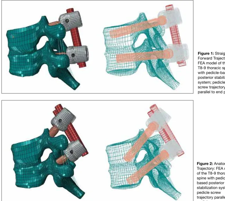
The transpedicular screw stabilization system was used for stabilization. The intact spine model was instrumented at the T8 and T9 levels with different trajectories of pedicle screws on the sagittal plane. Pedicle screws were directed parallel to the superior end plate (ST; Figure 1) and directed parallel to the pedicle (22° to the caudal; AT; Figure 2). Screws were inserted carefully in appropriate position.
Boundary and loading Conditions
The inferior surface of T9 was fixed, a 10 Nm bending moment was applied to the superior surface of the T8 vertebra in the intact spine, and the segmental and overall RoM was obtained in flexion, extension, axial rotation, and lateral bending. Follower load concept was used to apply 400 N as the body weight in each segment.
█
RESUlTS
Range of motion
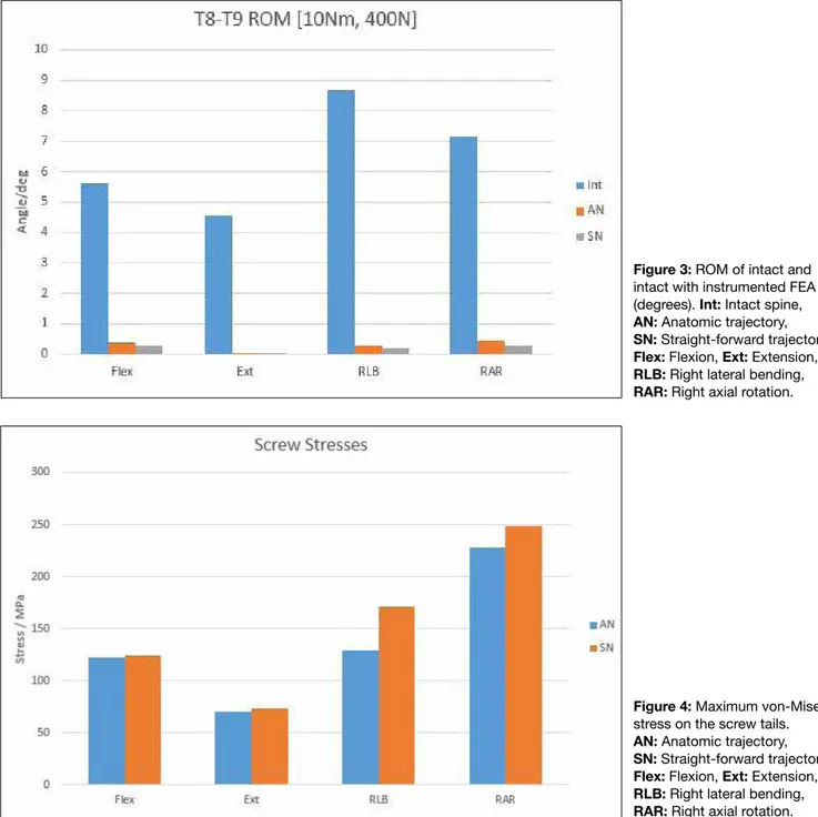
For intact spine, AT model, and ST model, the T8-9 segmental ROM was 3.2349°, 3.8944°, and 3.4941°, respectively, in flexion motion; 3.3013°, 3.9982°, and 3.3017°, respectively, in extension motion; 3.2967°, 2.7434°, and 4.8082°, respectively, in the right lateral bending motion; and 4.1376°, 2.8988°, and 3.7398°, respectively, in the right axial rotation motion (Figure 3).
Von-mises Stresses
The von-Mises stress is often used to determine whether an isotropic and ductile metal will yield when subjected to a complex loading condition. In addition, the structural safety for many engineering materials showing elasto-plastic properties (for example, steel or aluminum alloy) can be evaluated using von-Mises stress (30,33).
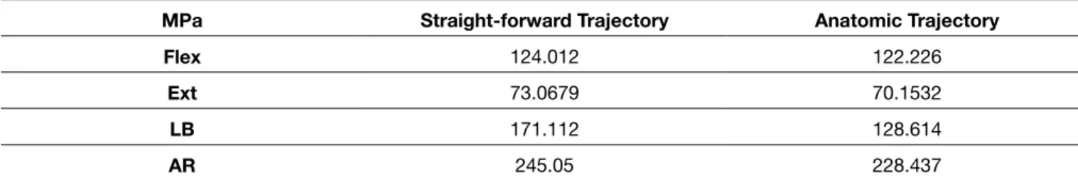
The maximum von-Mises stresses in transpedicular screws in MPa are presented in Table I for ST and AT models. In lateral bending motion, maximum von-Mises stress on screw tails in ST and AT models were 171.112 and 128.614 MPa, respectively. In axial rotation motion, maximum von-Mises stress on screw tails in ST and AT models were 248.050 and 228.437 MPa, respectively.
Both techniques showed different stress responses under physiological loadings. When pedicle screws were placed using AT, the maximum von-Mises stress in flexion and extension motions were decreased by 1.4% and 4%, respectively. The difference between both techniques was negligible in flexion and extension motions.
However, in lateral bending and axial rotation, FEA showed decrease in stress by 25% and 8%, respectively, when pedicle screws were placed using AT (Figure 4).
█
DISCUSSION
Transpedicular screw fixation of the thoracic spine has been used for various pathologies, such as trauma, tumor, deformity, infections, and degenerative diseases.
With wide application of the pedicle screw, clinical concerns have focused on the accurate placement of the screws. The majority of biomechanical studies have emerged detailing the accuracy and safety of transpedicular screw application in the thoracic spine. Unfortunately, when we reviewed the literature, Table I: Maximum Von-Mises Stresses in Pedicle Screws (in MPa)
mPa Straight-forward Trajectory Anatomic Trajectory
Flex 124.012 122.226
Ext 73.0679 70.1532
lB 171.112 128.614
AR 245.05 228.437
Figure 1: Straight-Forward Trajectory: FEA model of the T8-9 thoracic spine with pedicle-based posterior stabilization system; pedicle screw trajectory parallel to end plates.
Figure 2: Anatomic Trajectory: FEA model of the T8-9 thoracic spine with pedicle based posterior stabilization system; pedicle screw trajectory parallel to pedicle.
we recognized that the majority of pedicle screwing technique studies have been performed on the lumbar spine.
There are several investigation methods for the biomechanical study of the spine, such as using cadaveric spine, animal spine, and polyurethane foams. The finite element model is a valid and reproducible procedure for analyzing and saving the time, expenses, and effort of repeated biomechanical tests (8,17). Therefore, we used the finite element model in the present study.
There are varied techniques of pedicle screw insertion in the thoracic segment of the spinal column. In our study, we biomechanically evaluated the behaviors and stress responses of pedicle screws’ ATs and STs. AT and ST are two popular trajectories of pedicle screw insertion. In the AT model, pedicle screws were inserted parallel to the pedicle on the sagittal plane. Conversely, in the ST model, pedicle
screws were inserted parallel to the superior endplate on the sagittal plane. To the best of our knowledge, this is the first comparative FEA model study on the different insertion trajectories of pedicle screws in the thoracic spine.
Success of pedicle screw-based fusion depends on biomechanics and characteristics of the screw; insertion technique, such as screw trajectory; pedicle and vertebral anatomy; and patient’s bone quality (9). Many studies have reported major complications related to pedicle screw-based instrumentation, such as loosening, breakage, and pullout of the rods and screws. Several reports stated that the incidence of metallic failure was 4%–25% (10,23,24,34). At present, using the titanium instrumentation reduced the percentage of the complications related to the instruments (32). However, instrument-related complications with pedicle screws remain very crucial in spinal fusion surgery (1,18,19). In particular, screw
instrumentation and shielding the anterior vertebral column from physiologic compressive loads (15). Shifting of the compressive forces more posterior concludes higher stresses on pedicle screws and rods (15). In the present study, we evaluated the von-Mises stresses on the screw tails in the different screw trajectory models. In lateral bending and axial rotation, von-Mises stress on the screw tails decreased by 25% and 8%, respectively, when pedicle screws were placed using AT; consequently, insertion of the pedicle screw parallel to the pedicle provides less stress on the screw tail. Therefore, insertion of the transpedicular screws parallel to the pedicle could potentially prevent screws from loosening.
loosening is one of the most important factors that may cause failure of the fixation system. In the literature, the loosening rates of the pedicle screw range widely. The loosening rate was reported as 1%–15% in non-osteoporotic and 60% in osteoporotic patients (23). Screw loosening may be related to several factors, such as stress shielding, imbalance of the load sharing between columns, microfractures of the bones due to excessive loads, and high strains at the screw/bone interface due to insufficient support of the anterior column (12,16,27,28,32). Law et al. (20) indicated the importance of vertical compressive loadings in transpedicular screw loosening. distribution of the compressive loads is shifted toward the posterior of the spinal column by pedicle screw
Figure 4: Maximum von-Mises stress on the screw tails. AN: Anatomic trajectory, SN: Straight-forward trajectory, Flex: Flexion, Ext: Extension, RlB: Right lateral bending, RAR: Right axial rotation. Figure 3: RoM of intact and intact with instrumented FEA (degrees). Int: Intact spine, AN: Anatomic trajectory, SN: Straight-forward trajectory, Flex: Flexion, Ext: Extension, RlB: Right lateral bending, RAR: Right axial rotation.
6. Boucher HH: A method of spinal fusion. J Bone Joint Surg Br 41:248–259, 1959
7. Brodke dS, Bachus kN, Mohr RA, Nguyen Bk: Segmental pedicle screw fixation or cross-links in multilevel lumbar constructs. A biomechanical analysis. Spine J 1:373–379, 2001
8. Chao Ck, Hsu CC, Wang Jl, lin J: Increasing bending strength and pullout strength in conical pedicle screws: Biomechanical tests and finite element analyses. J Spinal Disord Tech 21: 130-138, 2008
9. Cho W, Cho Sk, Wu C: The biomechanics of pedicle screw-based instrumentation. J Bone Joint Surg 92-B: 1061-1065, 2010
10. davne SH, Myers dl: Complications of lumbar spinal fusion with transpedicular instrumentation. Spine (Phila Pa 1976) 17: S184–S189, 1992
11. dhawan A, klemme WR, Polly dW Jr: Thoracic pedicle screws: Comparison of start points and trajectories. Spine (Phila Pa 1976) 33(24): 2675-2681, 2008
12. El Saman A, Meier S, Sander A, Kelm A, Marzi I, Laurer H: Reduced loosening rate and loss of correction following posterior stabilization with or without PMMA augmentation of pedicle screws in vertebral fractures in the elderly. Eur J Trauma Emerg Surg 39(5):455–460, 2013
13. Erbulut dU: Biomechanical effect of graded facetectomy on asymmetrical finite element model of the lumbar spine. Turk Neurosurg 24(6): 923-928, 2014
14. Farshad M, Farshad-Amacker NA, Bachmann E, Snedeker JG, Schmid Sl: Biomechanical comparison of sagittal-parallel versus non-parallel pedicle screw placement. Acta Neurochir (Wien) 156(11): 2147-2151, 2014
15. Ha KY, Kim KW, Chang CH, Ha JY: Changes of fixation strength by rod-contouring of compact Cotrel-dubousset instrumentation. J korean orthop Assoc 33: 1134–1139, 1998 16. Huiskes R, Weinans H, van Rietbergen B: The relationship
between stress shielding and bone resorption around total hip stems and the effects of flexible materials. Clin Orthop Relat Res 274:124–134, 1992
17. Imai K, Ohnishi I, Bessho M, Nakamura K: Nonlinear finite element model predicts vertebral bone strength and fracture site. Spine 31: 1789-1794, 2006
18. Kowalski RJ, Ferrara LA, Benzel EC: Biomechanics of bone fusion. Neurosurg Focus 10: 1–7, 2001
19. Kutz SM, Denvine JN: Peek biomaterials in trauma, orthopedic, and spinal implants. Biomaterials 28:4845–4869, 2007 20. Law M, Tencer AF, Anderson PA: Caudo-cephalad loading of
pedicle screws: Biomechanisms of loosening and methods of augmentation. Spine 18: 2438-2443, 1993
21. lehman RA, Polly dW, kuklo TR, Cunningham B, kirk kl, Belmont PJ Jr: Straight-forward versus anatomic trajectory technique of thoracic pedicle screw fixation: A biomechanical analysis. Spine 28:2058–2065, 2003
22. Obernauer J, Kavakebi P, Quirbach S, Thome C: Pedicle-based non-fusion stabilization devices: A critical review and appraisal of current evidence. Adv Tech Stand Neurosurg 41:131–142, 2014
Lehman et al. (21) investigated two different insertion techniques by ATs and STs of transpedicular screws. They concluded that ST provided 27% higher pullout strength and 38% higher maximum insertion torque than AT. They advocated that ST is biomechanically superior to AT (21). However, Dhawan et al. (11) reported on trajectories and starting points of the thoracic pedicle screw and concluded that AT has several advantages in the thoracic spine. They reported that AT of the pedicle screw provides a 20% larger effective pedicle diameter in the sagittal plane; moreover, maximum insertional arc was obtained with AT. In contrast, a recent study concluded that different trajectories (sagittal-parallel versus non-parallel) of the pedicle screws showed no statistically significant differences in a calf lumbar spine model (14).
This difference may be explained by the fact that the human spine is not a homogeneous structure. The cervical, thoracic, and lumbar sections of the spine differ significantly from each other. In particular, characteristics of the vertebrae and positioning of the pedicles affect the load sharing of the vertebral column. Therefore, pedicle screw trajectory studies in different segments of the vertebral column do not exhibit similar results. The present study found that appropriate load sharing in the thoracic spine could be provided by pedicle screws inserted parallel to the anatomic load-bearing structures (AT). Thereby, stress on the pedicle screw tail and the rates of the pullout and breakage could be decreased. █
CONClUSION
AT resulted in 25% and 8% less von-Misses stress on the screw tail in lateral bending and axial rotation motions, respectively. AT reduced the von-Mises stress on the pedicle screws, thereby reducing the rates of screw breakage and diminishing fatigue risks. In addition, we believe that AT could buffer against screw loosening because the von-Mises stress of the internal fixation was scattered.
█
ACKNOwlEDGEmENT
Preparation for publication of this article is partly supported by the Turkish Neurosurgical Society.
█
REFERENCES
1. Asher MA, Carson Wl, Hardacker JW, lark RG, lai SM: The effect of arthrodesis, implant stiffness, and time on the canine lumbar spine. J Spinal disord Tech 20:549–559, 2007 2. Ashman RB, Galpin Rd, Corin Jd, Johnston CE: Biomechanical
analysis of pedicle screw instrumentation systems in a corpectomy model. Spine 14:1398–1405, 1989
3. Belmont PJ Jr, klemme WR, dhawan A, Polly dW Jr: In vivo accuracy of thoracic pedicle screws. Spine 26:2340–2346, 2001
4. Benzel EC, Baldwin NG: Crossed-screw fixation of the unstable thoracic and lumbar spine. J Neurosurg 82:11–16, 1995
5. Boos N, Webb JK: Pedicle screw fixation in spinal disorders: A European view. Eur Spine J 6:2–18, 1997
29. Shin TS, kim HW, Park kS, kim JM, Junk Ck: Short-segment pedicle instrumentation of thoracolumbar burst-compression fractures; short term follow-up results: J Korean Neurosurg Soc 42(4):265-270, 2007
30. Taylor GI, Quinney H: The Plastic Distortion of Metals. Phil. Trans. R. Soc., London, Vol. A230, 1931:323
31. Xu R, Ebraheim NA, ou y, yeasting RA: Anatomic consideration of pedicle screw placements in the thoracic spine: Roy-Camille technique versus open-lamina technique. Spine 23: 1065–1068, 1998
32. Villa T, La Barbera L, Galbusera F: Comparative analysis of international standards for the fatigue testing of posterior spinal fixation systems. Spine J 14: 695–704, 2014
33. Von Mises R: Mechanik der Festen Korper im Plastisch deformablen Zustand. Nachr. Ges. Wiss. Gottingen, 1913: 582
34. Yuan HA, Oarfin SR, Dickman CA, Mardjetko SM: A historical cohort study of pedicle screw fixation in thoracic, lumbar, and sacral spinal fusions. Spine (Phila Pa 1976) 19: S2779–S2796, 1994
23. ohlin A, karlsson M, duppe H, Hasserius R, Redlund-Johnell I: Complications after transpedicular stabilization of the spine: A survivorship analysis of 163 cases. Spine (Phila Pa 1976) 19: 2772–2779, 1994
24. ono A, Brown Md, latta ll, Milne El, Holmes dC: Triangulated pedicle screw construct technique and pull-out strength of conical and cylindrical screws. J Spinal disord 14: 323–329, 2001
25. yaman o, dalbayrak S: Idiopathic scoliosis. Turk Neurosurg 24(5): 646-657, 2014
26. Yaman O, Dalbayrak S: Kyphosis and review of the literature. Turk Neurosurg 24(4): 554-565, 2014
27. Schatzker J, Horne JG, Sumner-Smith G: The effect of movement on the holding power of screws in bone. Clin Orthop Relat Res 111: 257–262, 1975
28. Schizas C, Tzinieris N, Tsiridis E, Kosmopoulos V: Minimally invasive versus open transforaminal lumbar interbody fusion: Evaluating initial experience. Int Orthop 33: 1683–1688, 2009